9. Embedded programming
Group Assignment
Research & Reading the Atmel Datasheet
Processor
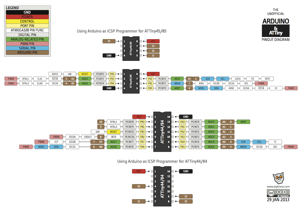
Read ATTiny datasheet.
From reading the datasheet, I can break down the properties of the chip/ factors to consider into the following:
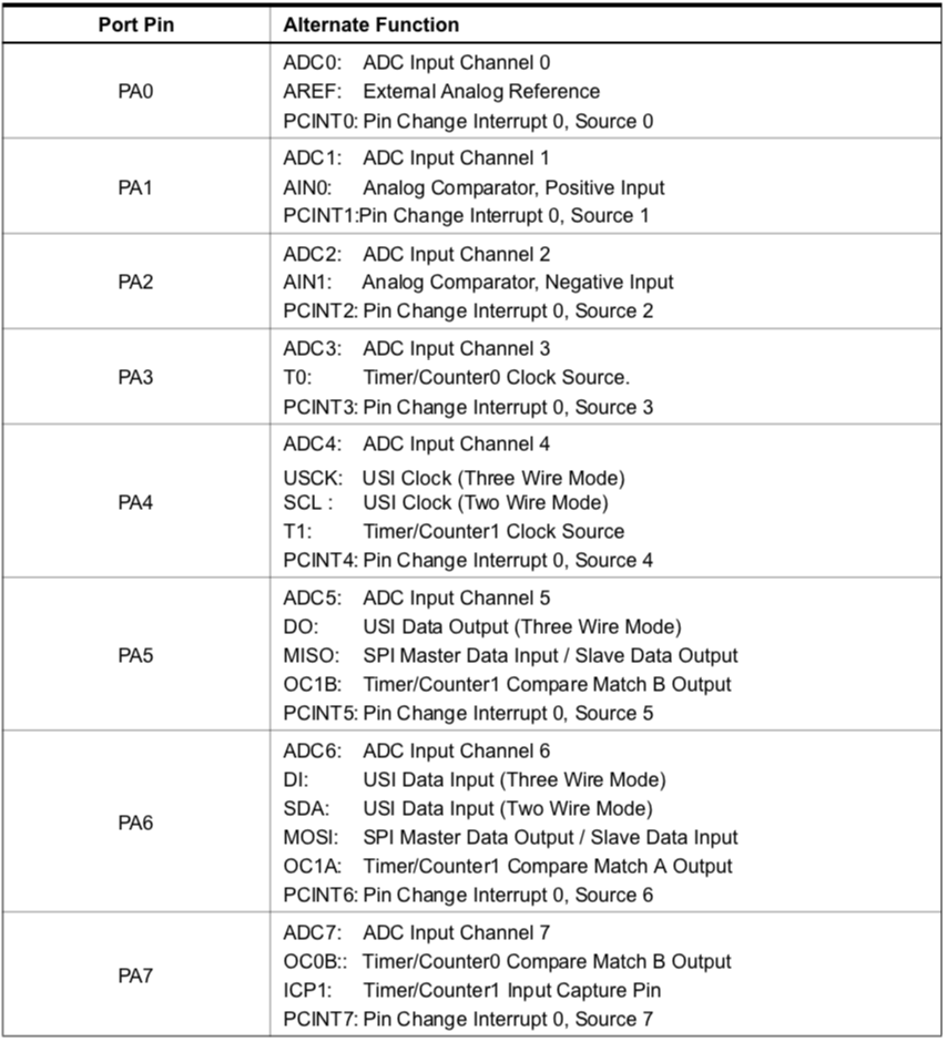
- Pins: I/O ports, VCC, GND, MISO,XTAL,MOSI and RST
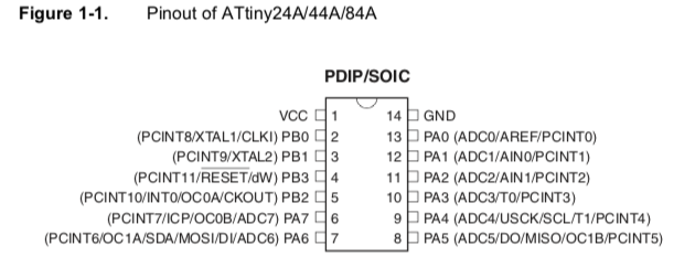
Not all I/O pins are created equal. Some pins have Analog properties which can be used for modulation for example stepper motors etc.If some pins are unused, it is recommended to ensure that these pins have a defined level. Even though most of the digital inputs are disabled in the deep sleep modes as described above, float- ing inputs should be avoided to reduce current consumption in all other modes where the digital inputs are enabled (Reset, Active mode and Idle mode).
The simplest method to ensure a defined level of an unused pin, is to enable the internal pull-up. In this case, the pull-up will be disabled during reset. If low power consumption during reset is important, it is recommended to use an external pull-up or pulldown. Connecting unused pins directly to VCC or GND is not recommended, since this may cause excessive currents if the pin is accidentally configured as an output.
-
Data storage/memory/registers: EEAR( Address register), EEPROM(Program memory)
-
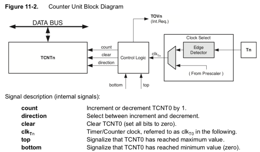
Timing/clock: CPU clock, I/O clock, Flash Clock, ADC clock, external clocks(with capacitors), Watchdog timer
-
Programming EEPROM & Flash: Program can be loaded through serial MOSI pin to the EEPROM using a programmer attached to a computer.
-
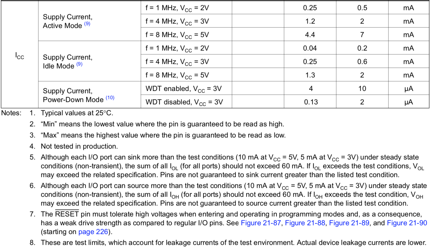
Power:

-
Resets: Power on, External(through RESET pin), Watchdog (through watchdog timer), Brown-out Reset
-
Processing: Analog Digital converter, output compare
-
Pin configurations & reading values:
-
Analog Digital Converter (ADC): The ADC converts an analog input voltage to a 10-bit digital value. The ADC is wired to a nine-channel analog multiplexer, which allows the ADC to measure the voltage at eight single-ended input pins, or between twelve differential pairs of input pins, or from one internal, single-ended voltage channel coming from the internal temperature sensor. Single-ended voltage inputs are referred to 0V (GND). ADC can be triggered without causing an interrupt.However, the Interrupt Flag must be cleared in order to trigger a new conversion at the next interrupt event. I want to learn further on this topic.

 10. Chip Voltage: Internal reference voltage of nominally 1.1V is provided on-chip. Alternatively, VCC can be used as reference voltage for single ended channels. There is also an option to use an external volt- age reference and turn-off the internal voltage reference.
-
Routes: Analog paths to be kept as short as possible to avoid noise.
-
Internal Sensors: Temperature
-
Reset pin: Can be used for external reset or for debugWIRE which is an onboard debugger that can emulate all on chip functions.
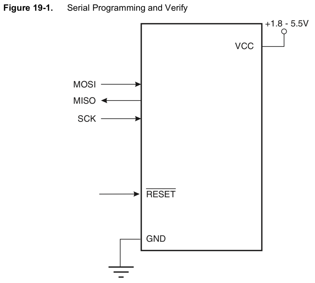
- Serial pins: MOSI, MISO & SCK.
Example code testing- Arduino
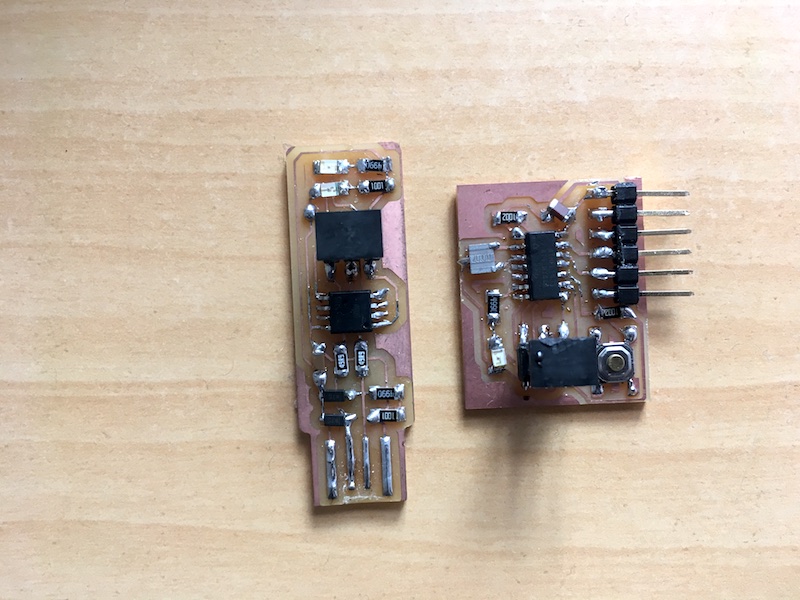
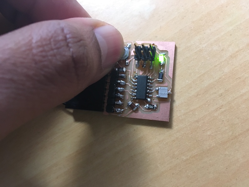
I tested the board if it showed up on my computer since I had a doubt if it would work on my USB 3.0 port, also since my soldering looked so bad! Making a smaller board was a bad idea.
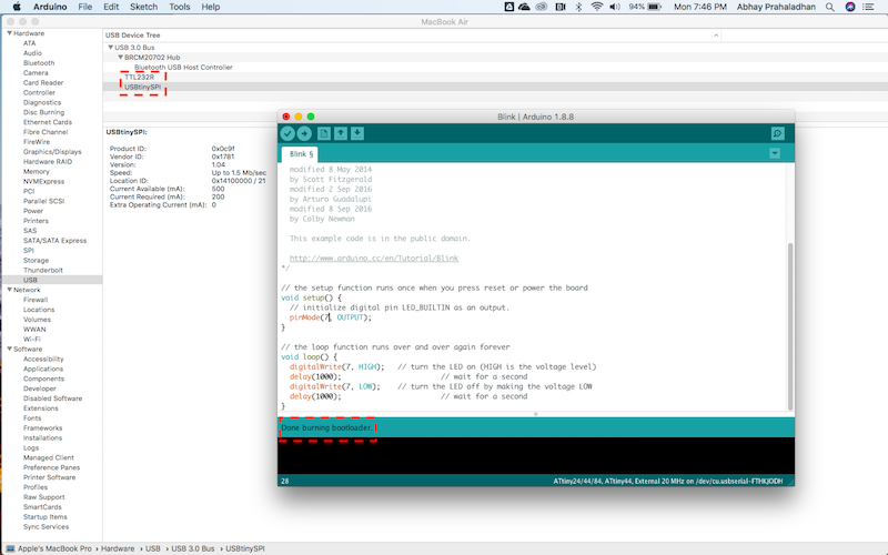
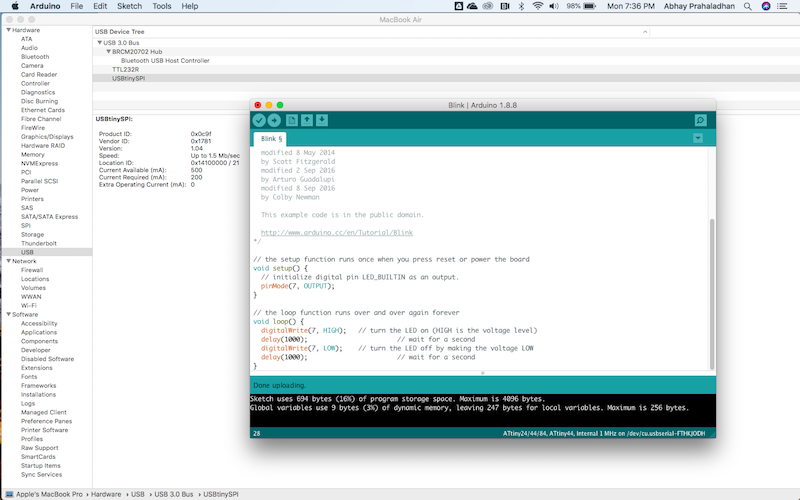
I uploaded an example Blink code from Arduino for testing the functionality of my board.
Then I tried the Button example code from Arduino I edited the following:
const int buttonPin = 3;
const int ledPin =  7;
Changing the buttonState value from 0 to 1 or vice versa controlled whether the button’s state when not being pushed was considered 1 or 0.
int buttonState = 0; // variable for reading the pushbutton status 1 or 0
Button fade Coding- Arduino
Additionally, I tried a few more lines of code to check analogWrite , primarily to see how the timer and brightness variables values work when given a fadeAmount input.
const int buttonPin = 3;     // the number of the pushbutton pin
const int ledPin =  7;      // the number of the LED pin

int led = 7;           // the PWM pin the LED is attached to
int brightness = 0;    // how bright the LED is
int fadeAmount = 5;    // how many points to fade the LED by

// variables will change:
int buttonState = 0;         // variable for reading the pushbutton status

void setup() {
// initialize the LED pin as an output:
pinMode(ledPin, OUTPUT);
// initialize the pushbutton pin as an input:
pinMode(buttonPin, INPUT);
}

void loop() {
// read the state of the pushbutton value:
buttonState = digitalRead(buttonPin);

// check if the pushbutton is pressed. If it is, the buttonState is HIGH:
if (buttonState == LOW) {
// turn LED on:
digitalWrite(led, HIGH);
} else {
// turn LED off:
analogWrite(led, brightness);
// change the brightness for next time through the loop:
brightness = brightness + fadeAmount;

// optional reverse the direction of the fading at the ends of the fade:
if (brightness <= 0 || brightness >= 255) {
fadeAmount = -fadeAmount;
}
// wait for 30 milliseconds to see the dimming effect
delay(30);
}
}
Analog & Digital write work when coded through Arduino!
Hello Echo coding through Terminal
Setup
For the next challenge I wanted to upload some C code to the board using Terminal. To do this I followed the FabAcademy tutorial but it is incomplete as it didn’t have the detailed make command.
So, my colleague Rodrigo Gamboa from the IED Fablab suggested another tutorial This link has a better explanation of how to do it.
Download these two files by right-clicking and selecting Save As:
I recommend to put the two files into a folder. I named the folder /originals/Embedded_Programming/ in the folder I have on GIT.
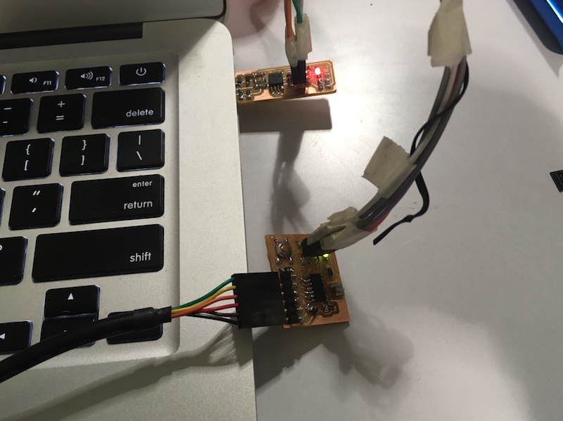
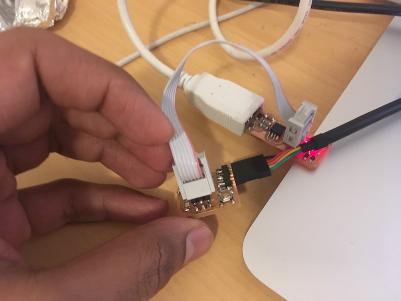
- Connect the programmer to the ISP header on the LED + Button board
- Provide power to the button board, if the RED LED on your programmer lights up brightly, then move on to the next step, else check orientation of header pin connection.
- You’ll need to provide power to both your board and your programmer (FabISP).
- On a Mac, check apple/about this mac/system report/USB to see if your USBTiny and your FTDI is detected to ensure everything is connected correctly.
- Ensure
PROJECT=hello.ftdi.44.echoin the .make file matches the same name as the .c file. I used XCode on a Mac to check the code within these files.
Set fuses and load program
Now you can begin to load the Hello Echo program to the board. Since I have already burnt the bootloader from Arduino in the previous part of the assignment, I am directly starting with the following steps:
First cd to your folder where the .c and .make files were saved.
And run the following code to make fuses to ensure no errors:
make -f hello.ftdi.44.echo.c.make program-usbtiny-fuses
You can also test the serial ports on Arduino Serial monitor to check if its all ok.
Check if the “baud” value comment in the .c file is used in the Serial monitor. Now test if your inputs are passing correctly. If you see jumbled letters, its probably a mismatched baud.
If you see ” Fuses OK” on the Terminal, move on to the next step:
make -f hello.ftdi.44.echo.c.make program-usbtiny
You should now see a bunch of code and no errors with a messages like “… of Flash verified” and “fuses OK”
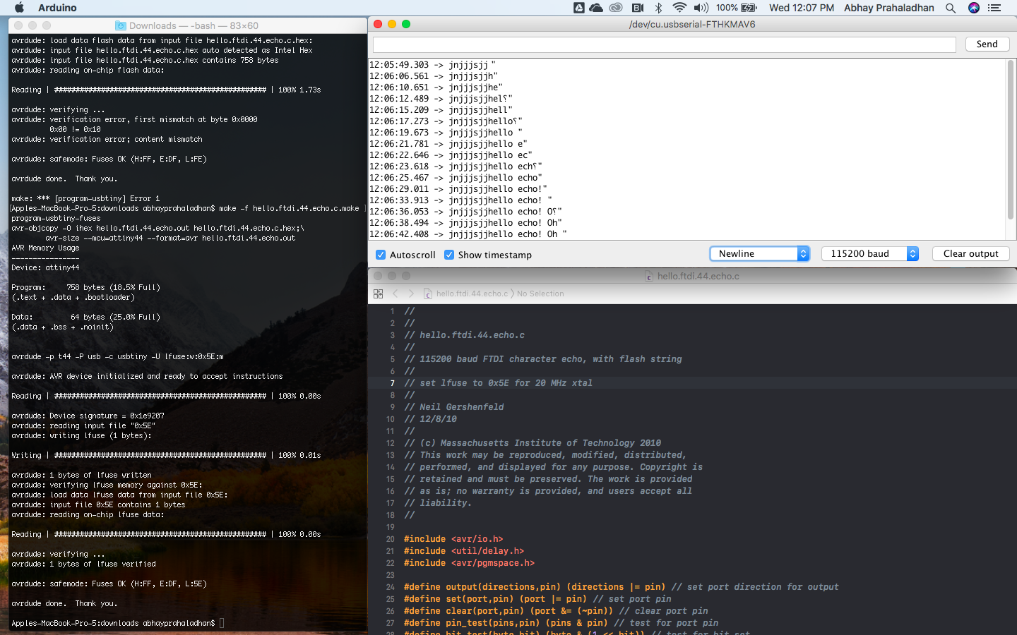
Testing
If you had already uploaded a code for the LED through Arduino, that code would’ve been erased by now and the LED effect would have stopped. This is a first sign that a code was erased on the board and maybe a new one was loaded.
Now you can test out your code. Open Arduino and go to “Serial Monitor” and start typing a letter and hit enter.
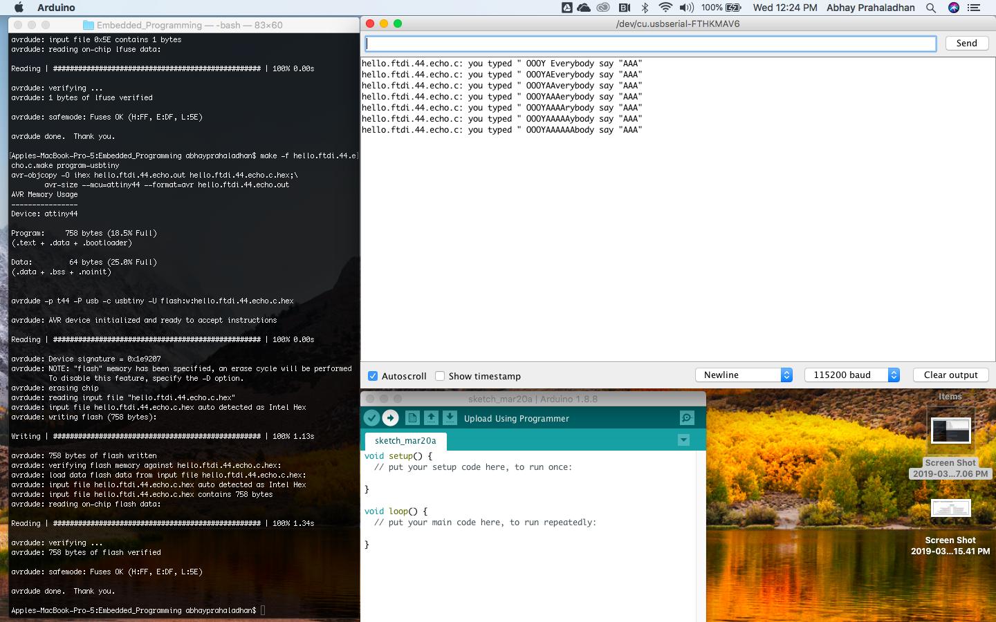
You should see that the Serial monitor displays a “you typed” followed by an echo of what you type. The Hello Echo program is now tested on your board.
Button coding through Terminal
I tried coding the button and LED through C and Terminal using a file by my instructor Marta Verde
Excerpt of C file:
int main(void) {
//initialize output pins
set(button_port, button);
input(button_direction, button);

set(led1_port, led1);
output(led1_direction, led1);

clear(led1_port,led1);

//main loop
while (1) {
if(0 == pin_test(button_pins, button)){
set(led1_port,led1); //LED ON
} else {
clear(led1_port,led1); //LED OFF
}
}
}
Terminal code:
cd to the folder and type
make -f helloButton.c.make program-usbtiny-fuses then
make -f helloButton.c.make program-usbtiny
Wait for a bunch of code to execute and test the button:
I want to try more complicated code on C and also most of the programming shown in the datasheet. I want to learn to use the ADC. I also want to try other IDE like Eclipse.
Arduino vs C
There isn’t really an Arduino language as such. It’s really just C++ with some domain-specific libraries. These add on various features, such as functions you can call to control the hardware. #include commands
if you have previous programming experience and you are aware of concepts as OOP, it is better to go for C/C++. The arduino language is really great for beginners, but have some limitations (e.g. you must have all your files in the same folder). And it is basically a simplification of C/C++ (you can practically copy&paste arduino code to a C/C++ file, and it will work).
More differences between Arduino and C++ are in the memory storage. Usually a modern computer has more than 2GB of RAM, while the Arduino Uno has 2kB (1 million times less). The Arduino also uses 8-bit instructions in stead of the 32 bit ones a computer uses. This will mainly affect the amount of information you can store in a variable.
References
- Octopart
- Arduino code cheatsheet
- C Programming cheat sheet
- ATTiny condensed Datasheet
- ATTiny original Datasheet