7. Electronics design
Group assignments
Research
Kirchoff’s law
P=IsquaredR= IV
Mosfet for adjusting current flowing to component vs Resistor?
Mosfet heatsink
Programs
Drawing
Ki Cad Eagle
Auto routing: Complex math problem, better to design yourself. Board size 3D viewing Board layers for crossing lines or can use a few 0 ohm reistors to skip.
Simulator
Falstad Spice
Debugging
Check voltage at microprocessor pins Use oscilloscope
Installing Eagle, Libraries & Design rules
I tried Eagle for the first time and had targeted to make the Hello Echo board smaller. After installing the software, I had to install the Fab library and the design rules for ensuring that the components used in the fablab are the same in my drawing and to ensure the router can mill the smallest of traces.
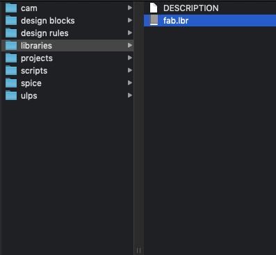
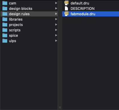
Copy the two files into the Eagle folders under Documents as shown in the images above.
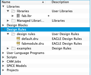
You should now see the two files show up in your Eagle control panel.
Design of the Hello Echo board on Eagle
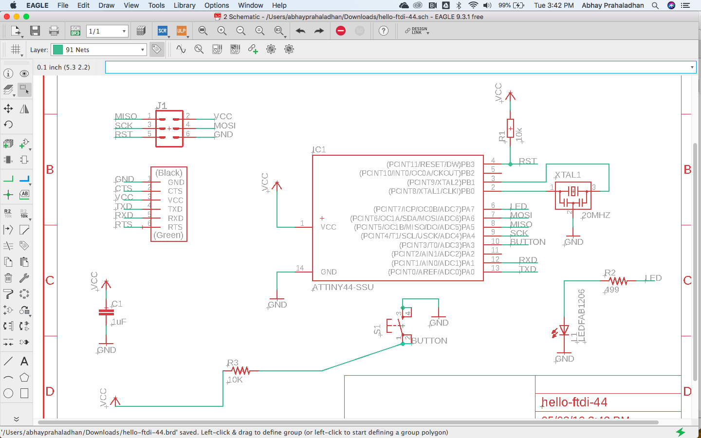
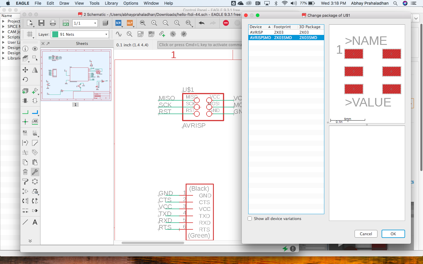
I learnt that there are two types of views in Eagle, Board and Schematic. The Schematic is used to organise the logic of the circuitry before designing the physical layout of the same in Board view.
I first made the schematic as per Neil’s tutorial to ensure functionality since I’m new to electronics. Yet, I wanted to optimise the size of the board, since I’m an Architect.
Connecting the NET with a NAME is a good way to organise the schematic wirelessly. eg. Two or more NETs with the same NAMEs will be connected wirelessly in schematic and the same will reflect in the BOARD.
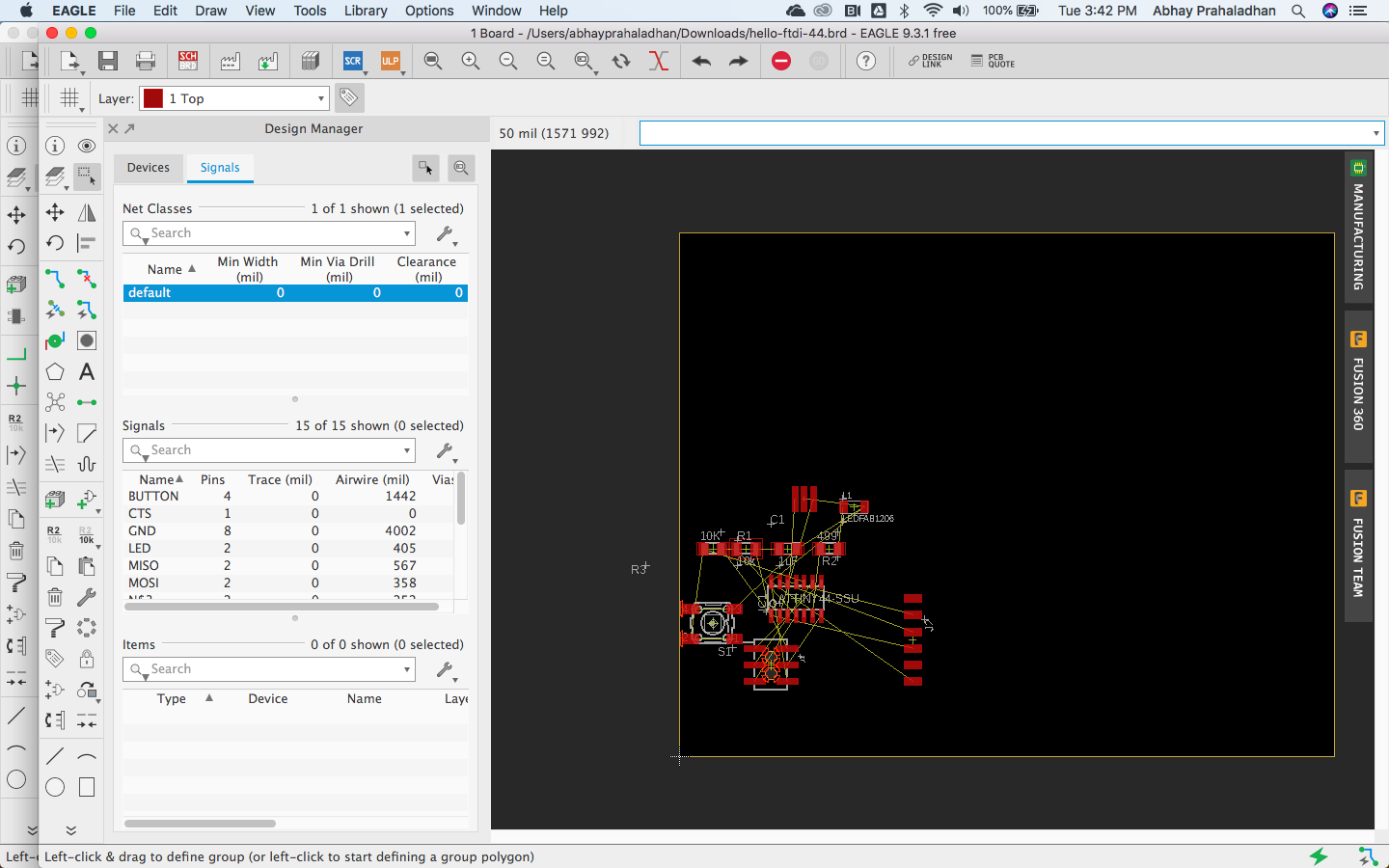
MOVE the components around before you ROUTE the traces. I tried the AUTOROUTE command but it gave me a very large board, which was not my goal.
DRC: Check design through Eagle with the installed fabmodule.dru for errors.
Failure! I could not connect the routes efficiently with this current design approach.
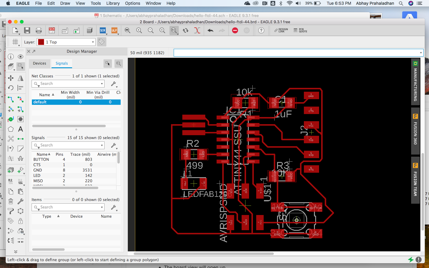
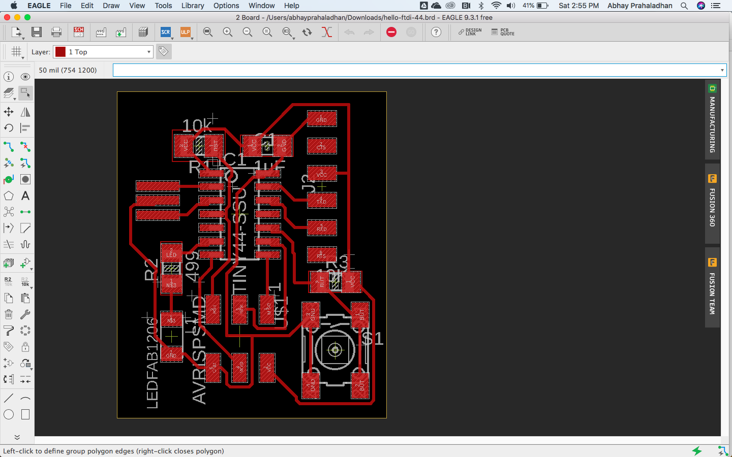
I tried again with a newer design approach:
I learnt the following: - The ATTiny 44 is an entry level processor for basic operations - The 20MHz oscillator is being used for improving the clock speed and accuracy of the processor. - LEDs need resistors to limit current flowing through it to protect it from burning out. - A capacitor is necessary to be connected to the processor to filter current - Ensure the footprint of the components from the Eagle library are the same as what you physically have with you in the lab.
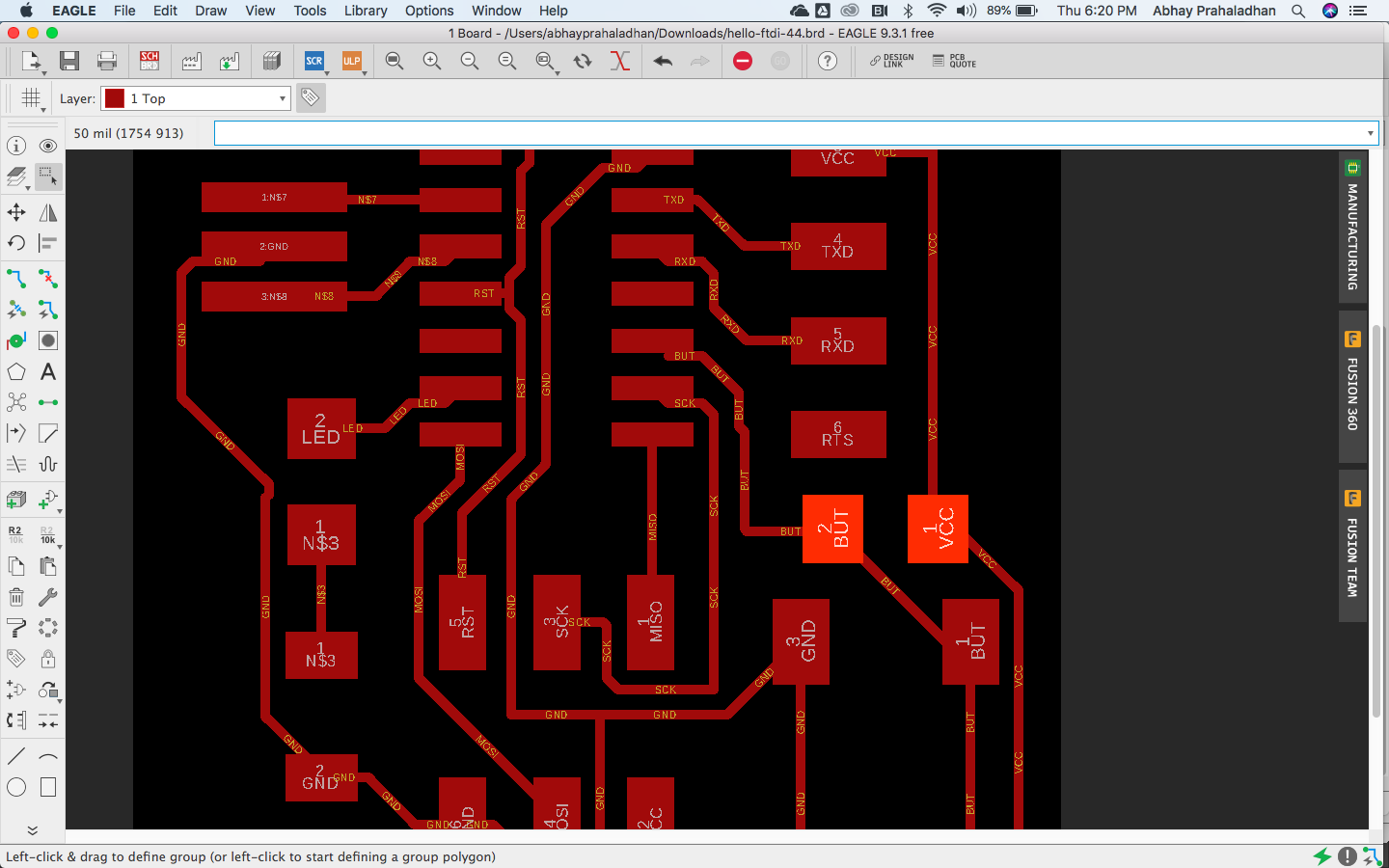
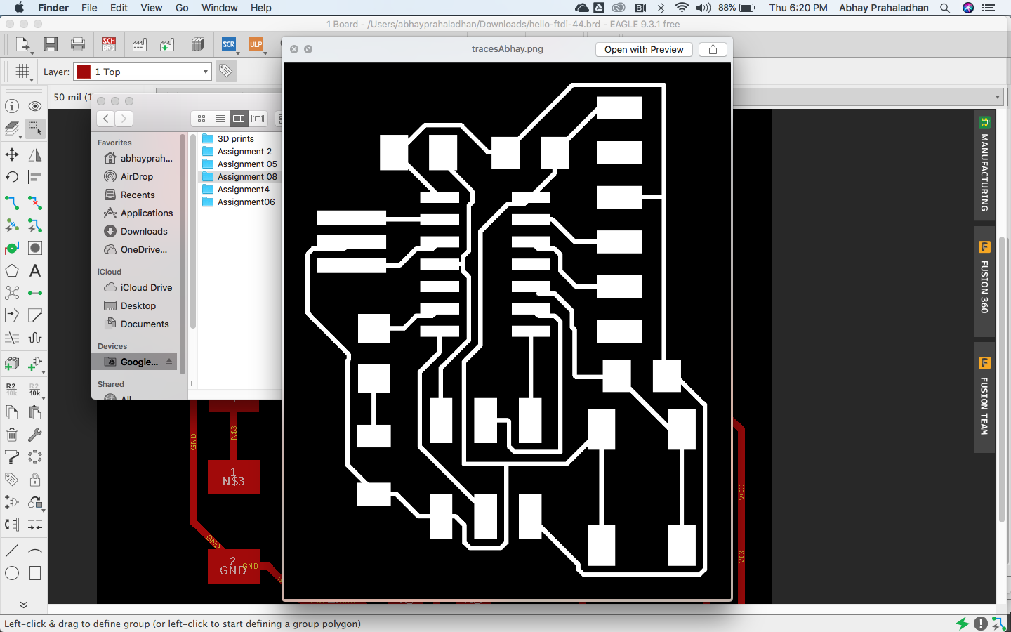
The NAME of the button pin was showing up on the traces file bigger than the pad. This would’ve created an issue while cutting and had to be corrected.
Hence I shortened the name to fit within the pad and it worked.
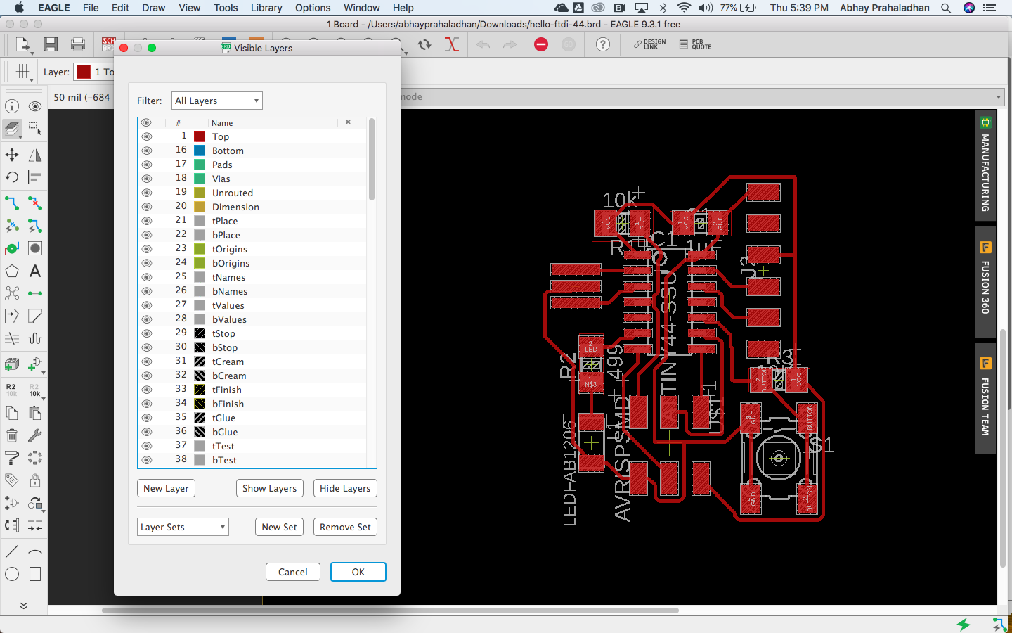
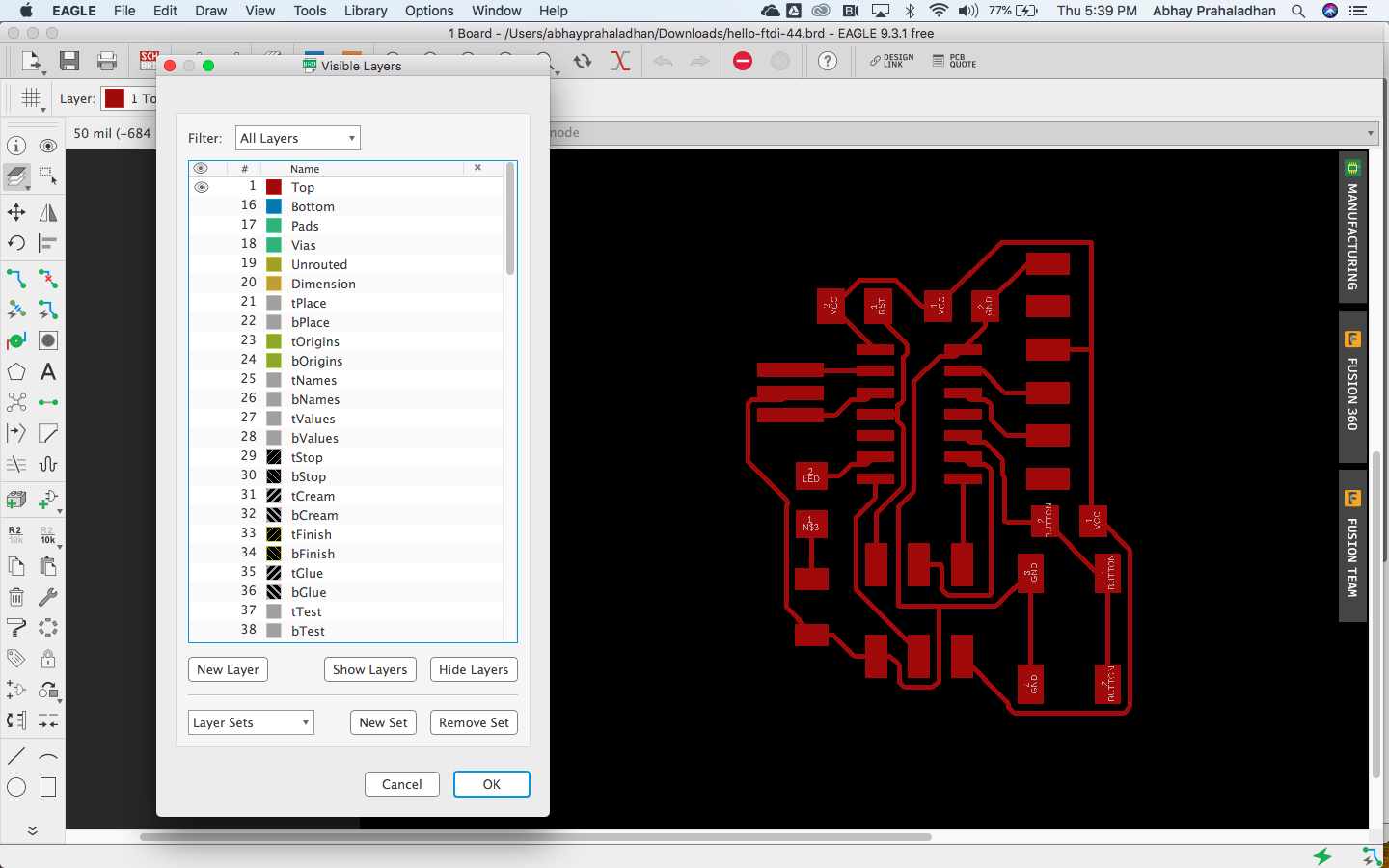
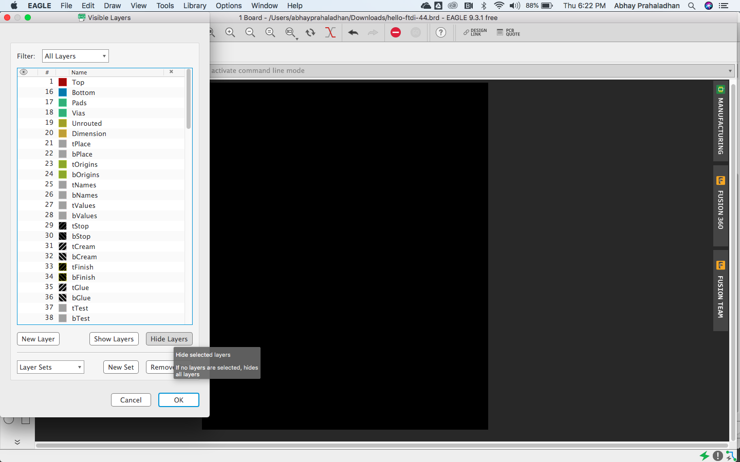
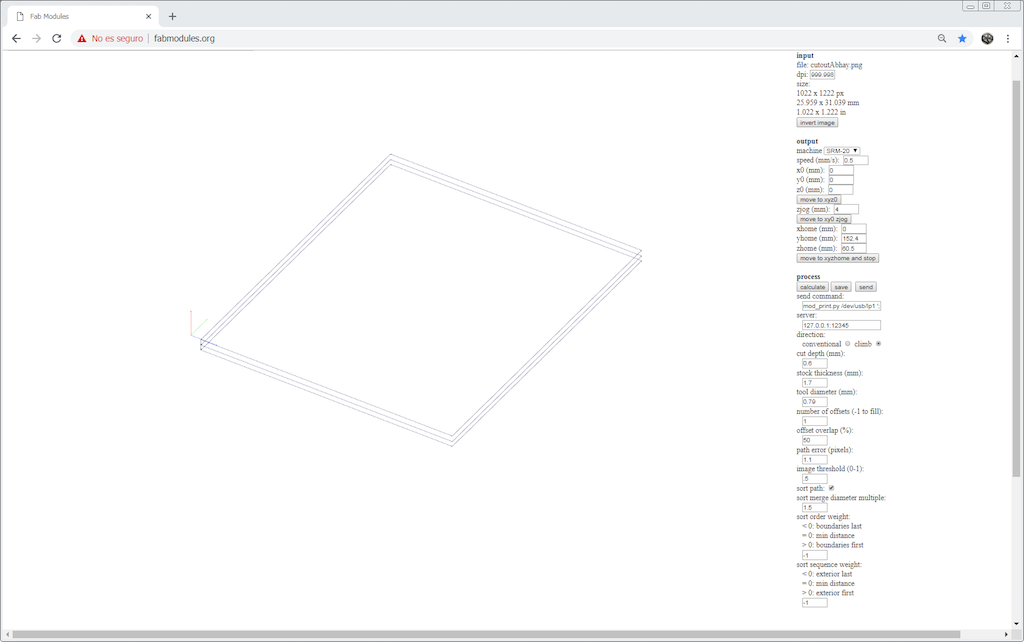
I exported the file to PNG at 1000dpi and monochrome with only the selected layers turned on. The dimension layer was creating an issue if it was on.
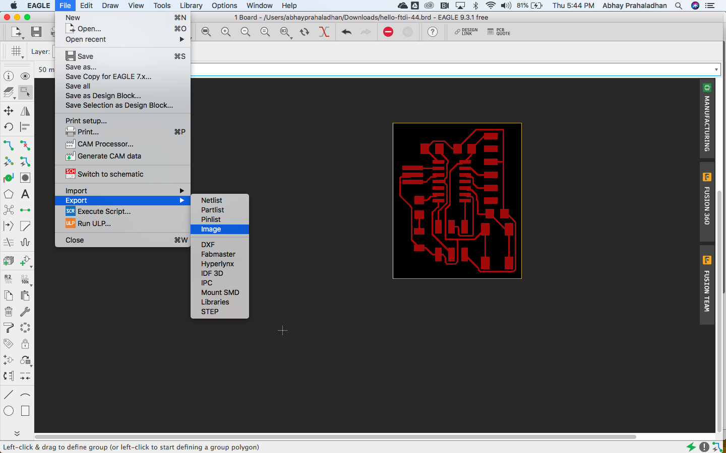
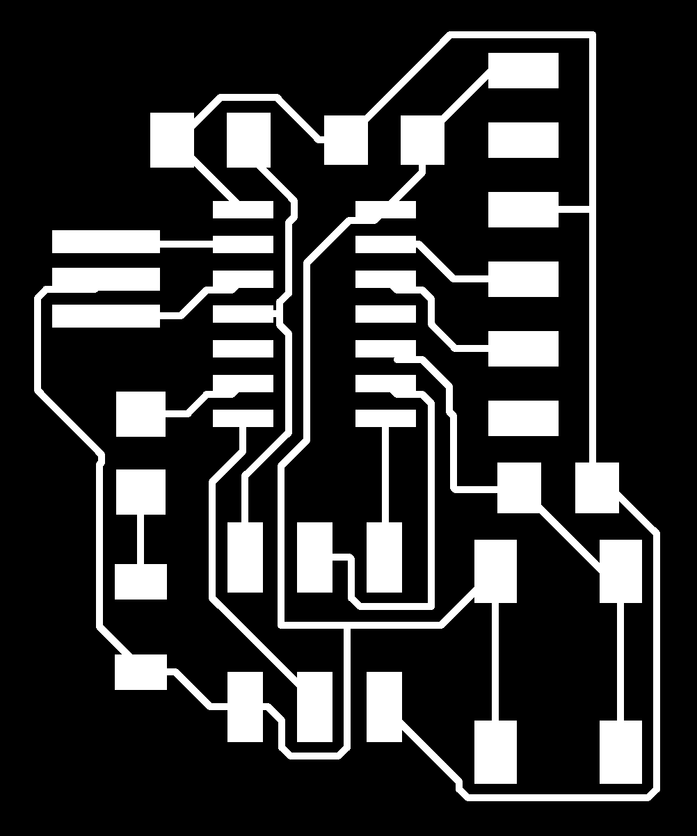
Dimension layer was turned on only during the export of the cut out image.

File is ready to be milled, it will be physically smaller than Neil’s board in the tutorial.
Production
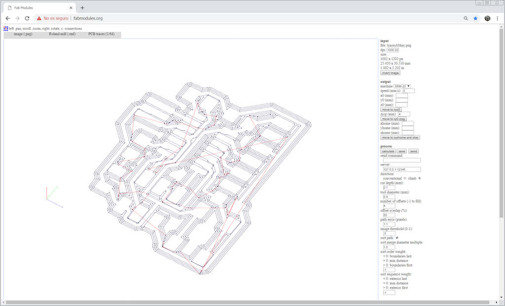
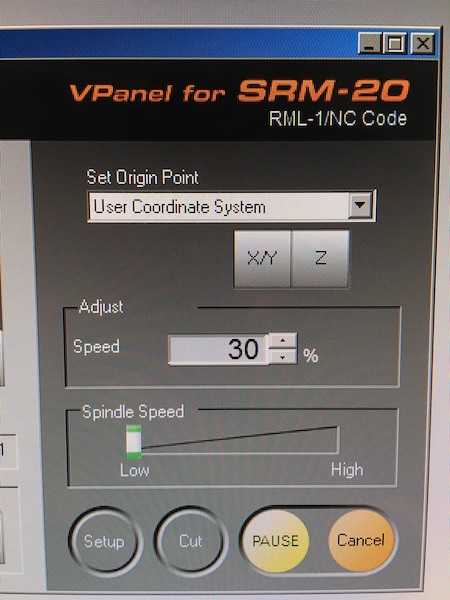
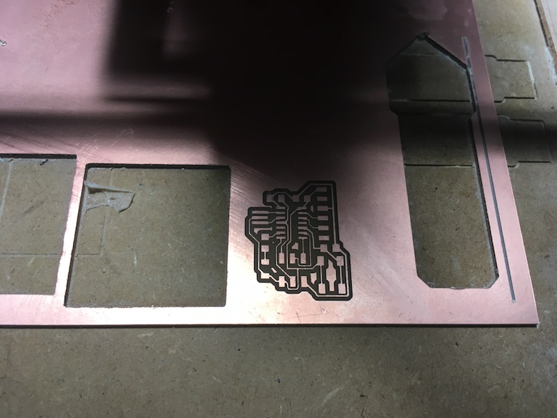
While milling the board on the Roland SRM 20, I followed the same method I followed in the previous assignment and created an rml file using mods.
I burnt the board by using a very hot soldering iron.
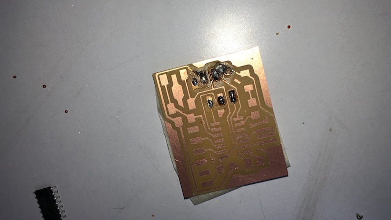
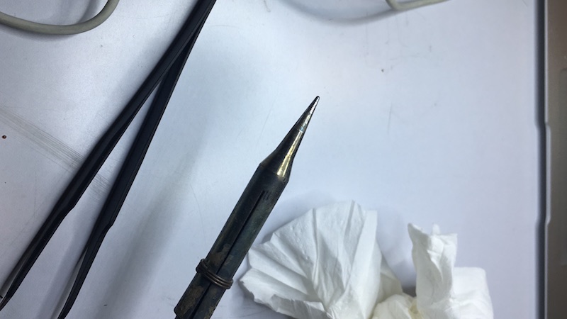
So I milled another board and soldered the components with an iron which controls the temperature accurately.
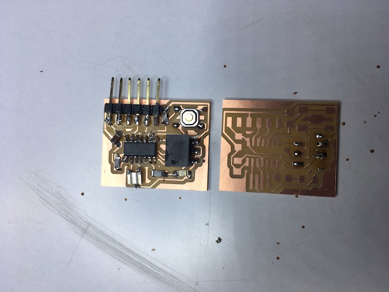
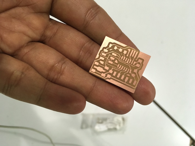
Success! I achieved the smallest board among my peers with the same components & function, which was what I was ROUTEing for! Hehe.