11. INPUT DEVICES
Goal
Measure something: add a sensor to a microcontroller board that you have designed and read it
Doing
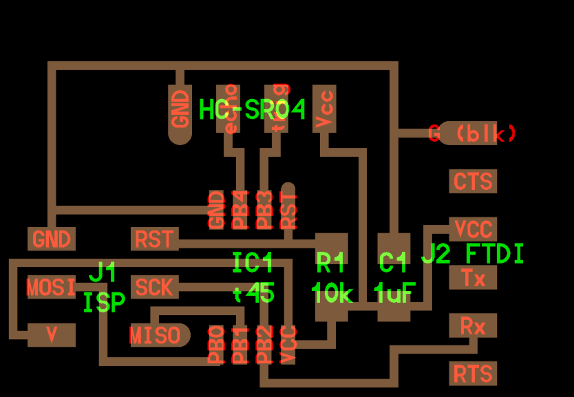
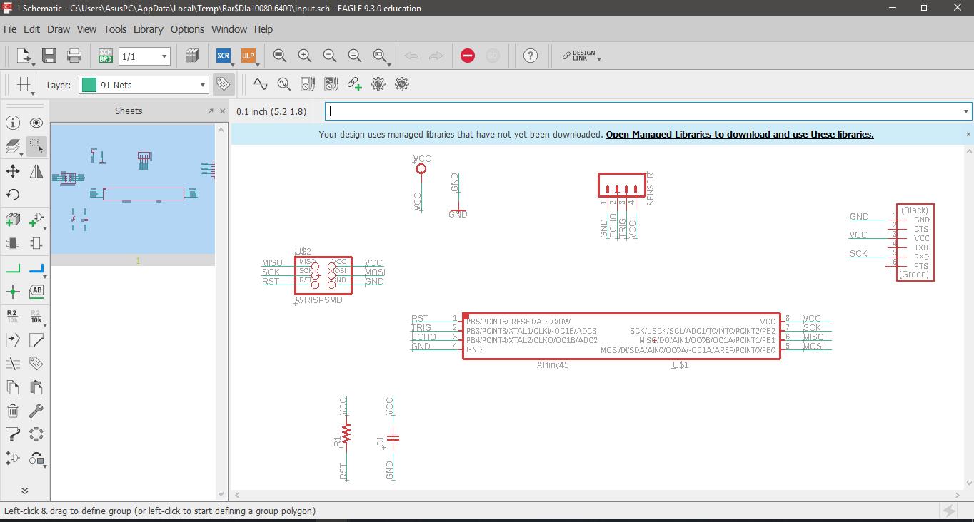
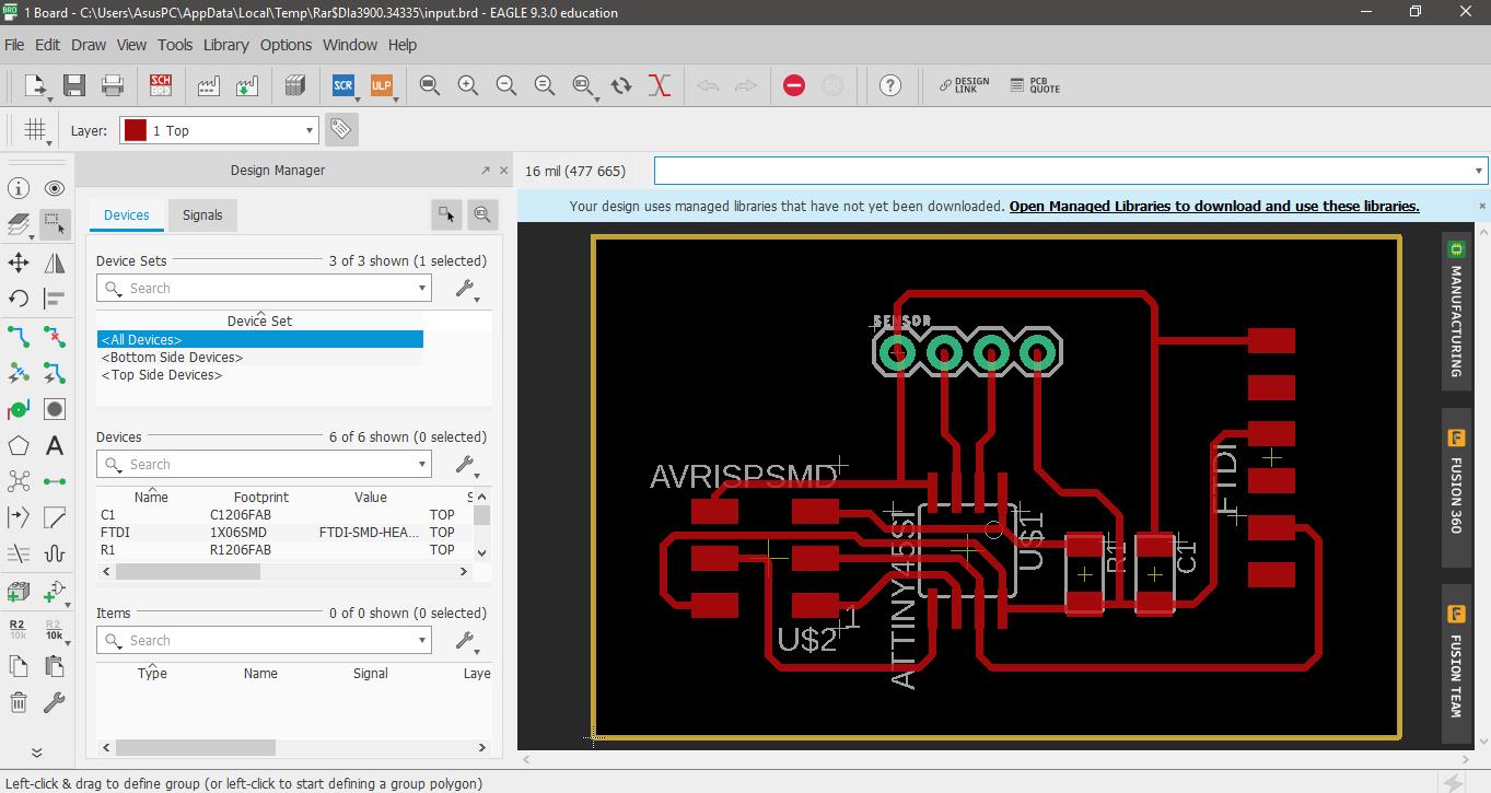
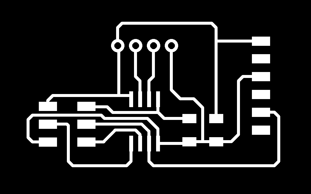
First I were guided of this board that is on the page of the fabacademy. I drew the board in Eagle Program
In the clearence option was placed 16 mill, by the reference of the size of wood milling cutter that will be used.
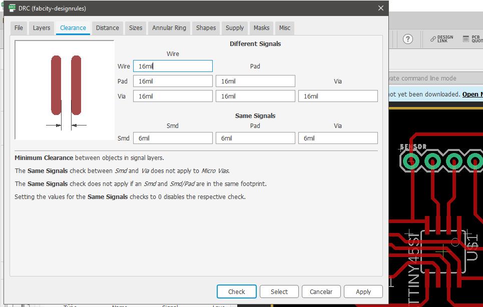
I used the width 16 because it does not use a lot of voltage.
I exported the milling part in png format (600dpi)
Milling
Also to be able to milling the plate, I used of the Roland Modela Machine
Then, I opened the PNG file, in the software of the MODELA, opened the terminal and mill the design on a copper blad board.


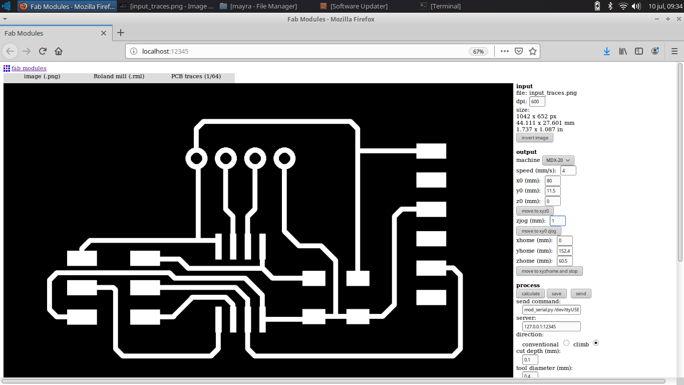
Before, I put the parameters in the Fab Modules to have a good milling. I opened the Fab Modules I chose the process of mill (.rml) in which input is image (.png)
I started with the rough (traces 1/64),.It is important to modify the parameter of Path error (pixel) which by default is 1.1 and it is changed to 0.1
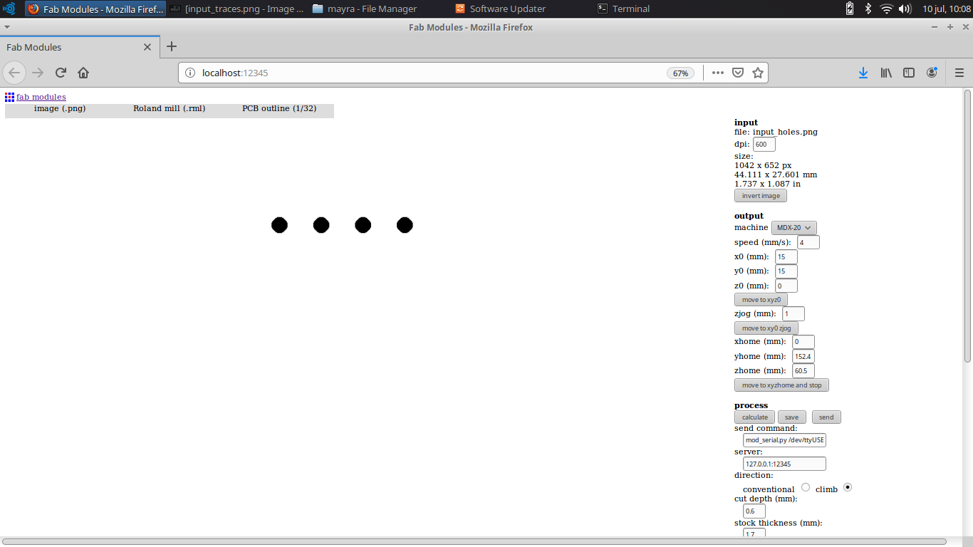
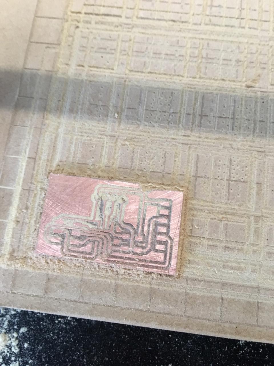
I continued with the finish process (outline 1/32)
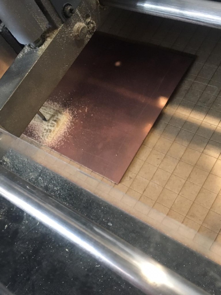
We can see the milling of the board
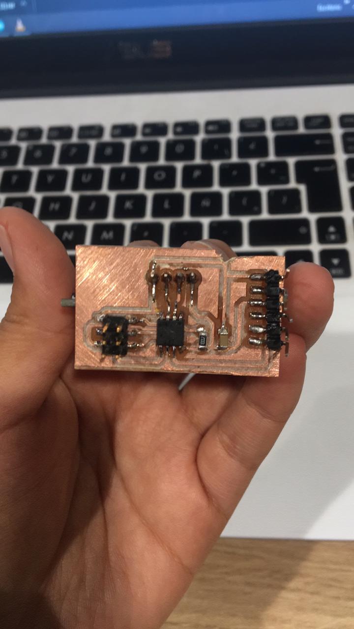
Then I soldered the board with the materials provided by the Fab Lab Esan.
Programming
To burn the bootloader, I need to identify the port in wich the FTDI cable was pluged,
Then in the tool tab, begin to set the information, board, processor, port.
Also, For this assignment I used the USBasp recorder because my isp recorder did not work
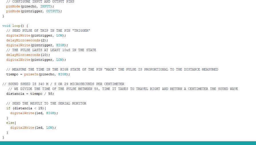
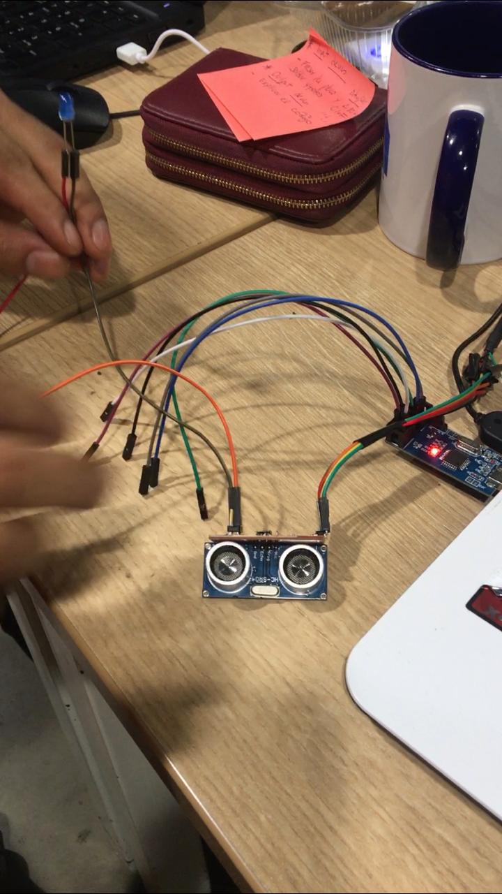
I did this programming because my board could not transmit serial communication in the Arduino, so I used a led to activate communication
which consisted,the ultrasound detects an obstacle in less than 15 cm, it activates the led, otherwise it goes out
Explaining the code
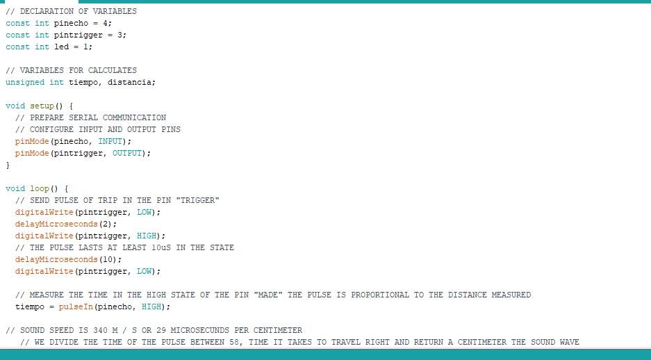 )
)
 )
)
You can see the video
You can download the files by clicking on the bullets point.