7. ELECTRONICS DESIGN
Goal
Redraw the echo hello-world board, add (at least) a button and LED (with current-limiting resistor), check the design rules, make it, test it.
DESIGN
First, download the EAGLE Program, which allows you to design plates with their components and make paths.
Redraw the echo hello-world board
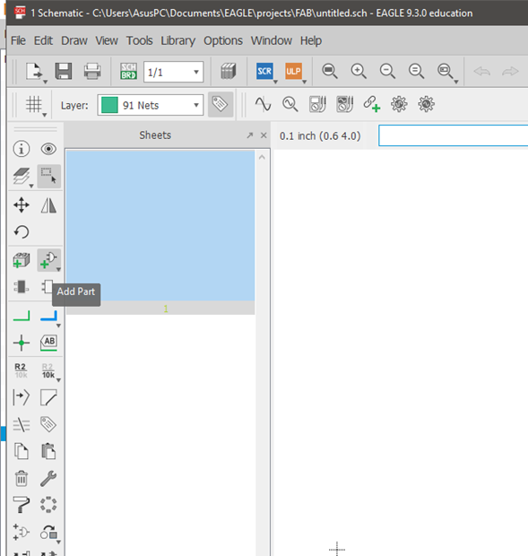
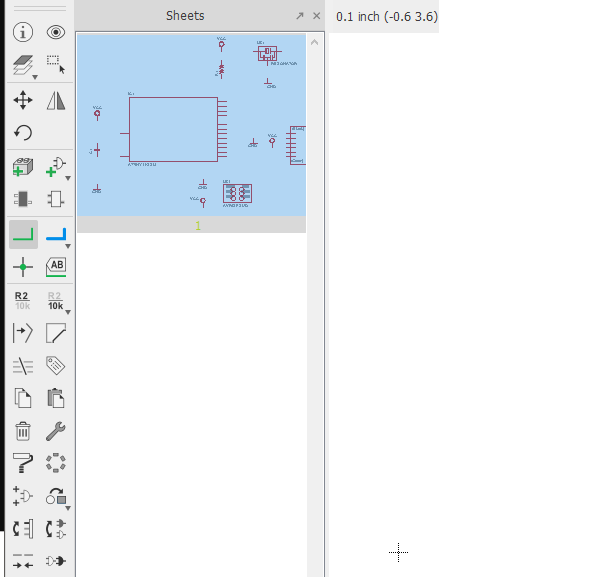
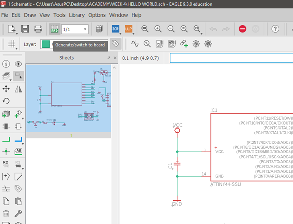
I created a new document schematic
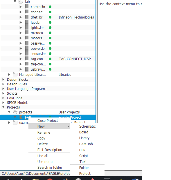
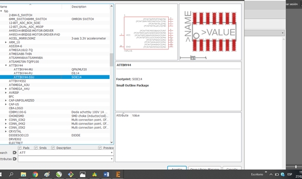
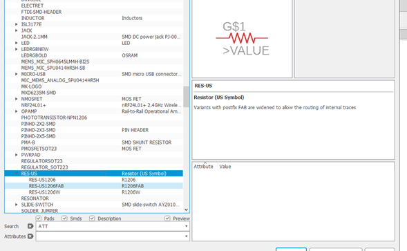
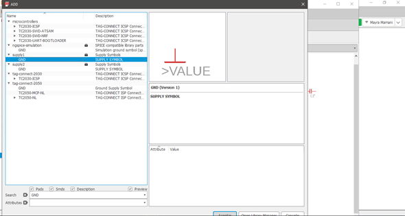
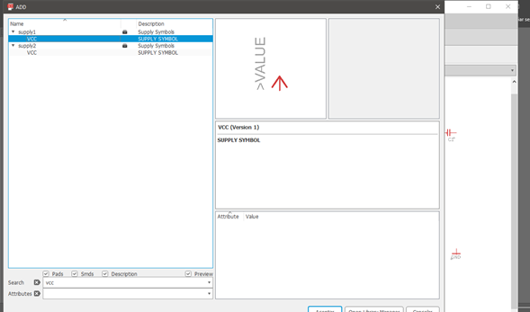
I applied the option “Add part” Then, download the FABACADEMY website to find the necessary components on the board. And, I was extracting from the repository every necessary component, and added a led plus a button, and resistance.
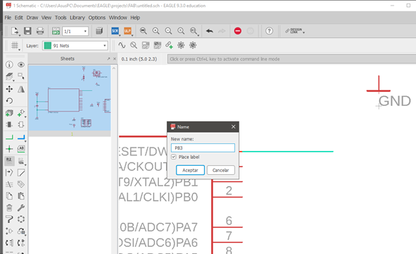
Then, begin to link each component with the ATTINY according to the digital terminal.
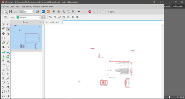

I put name “PB3”
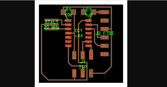
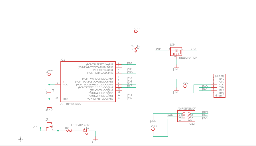
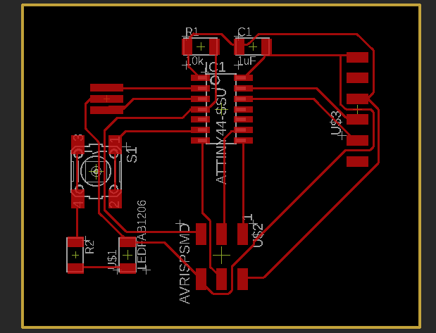
You can see the electronic design I added a resistor, led, and a button
I applied the option “Generate/switch to board”
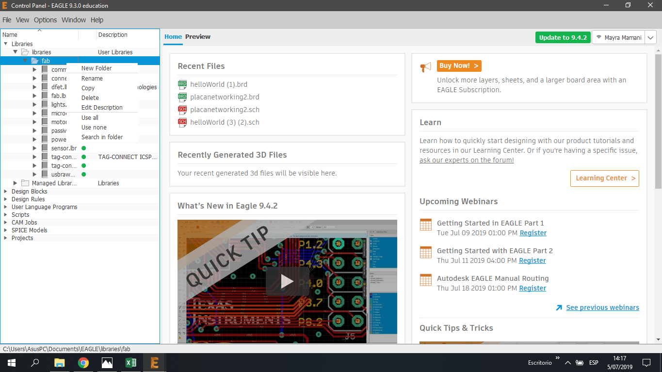
Before entering the DRC option, I installed and enabled the fab library, I put the option “Use all”
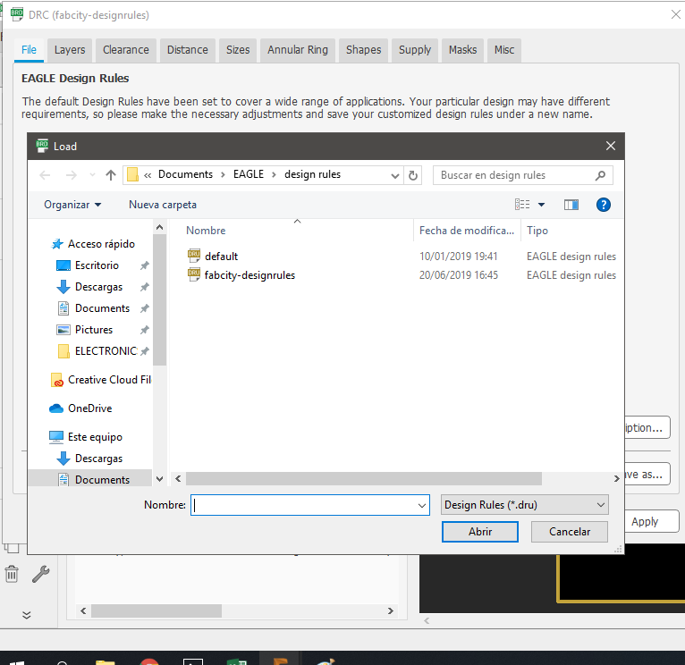
After I went to the Design rules (DRC) option, I loaded the fabcity-designrules library.
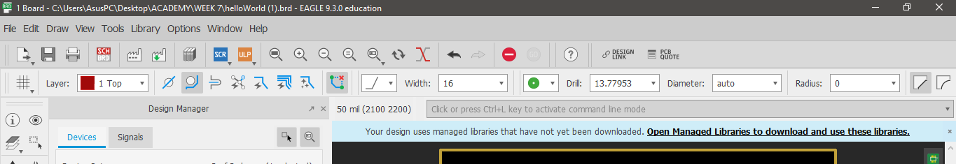
In the clearence option was placed 16 mill, by the reference of the size of wood milling cutter that will be used.
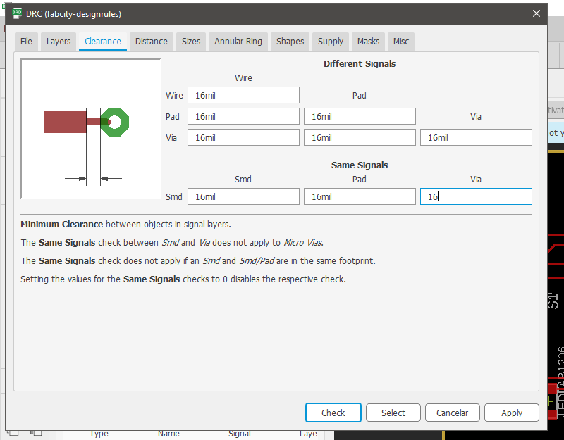
I used the width 16 because it does not use a lot of voltage.
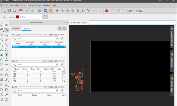
I ordered the components of the plate
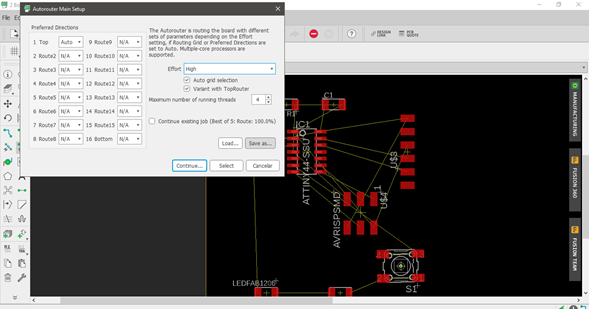
I applied the option “Autorouter Main Setup”
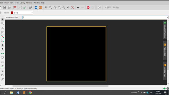
I drew an outer square to delimit the space on the board.
I exported the milling part.
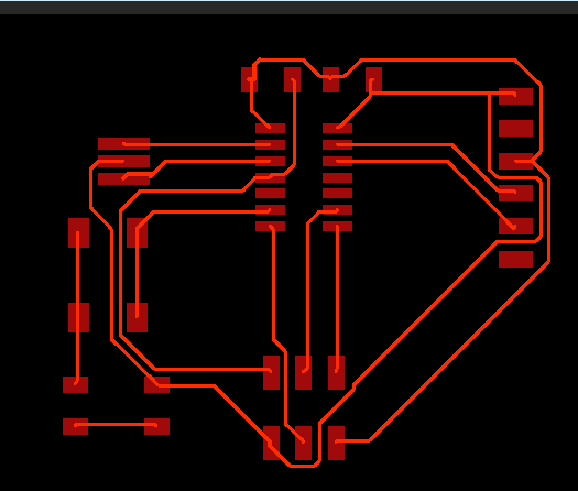
I exported the outer cut.
You can download the files by clicking the bullets below.
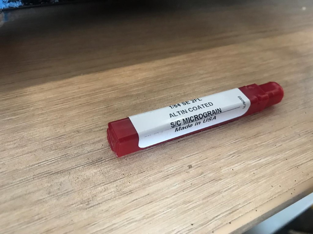
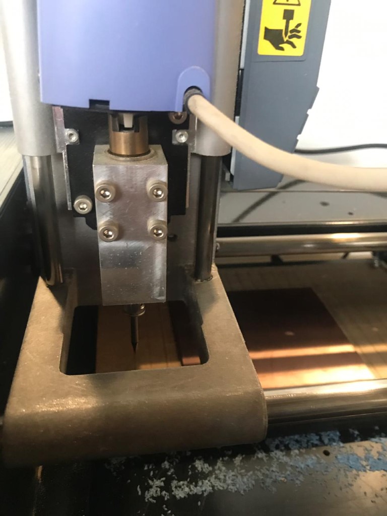
MILLING
Also to be able to milling the plate, I used of the Roland Modela Machine
Then, I opened the PNG file, in the software of the MODELA, opened the terminal and mill the design on a copper blad board.
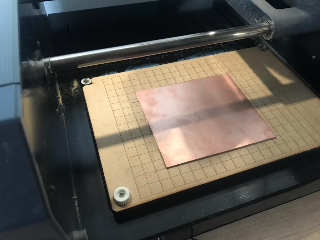
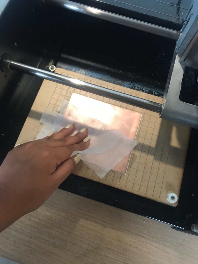
I cleaned the board
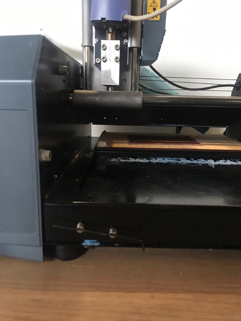
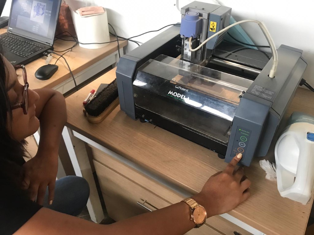
Started to mill
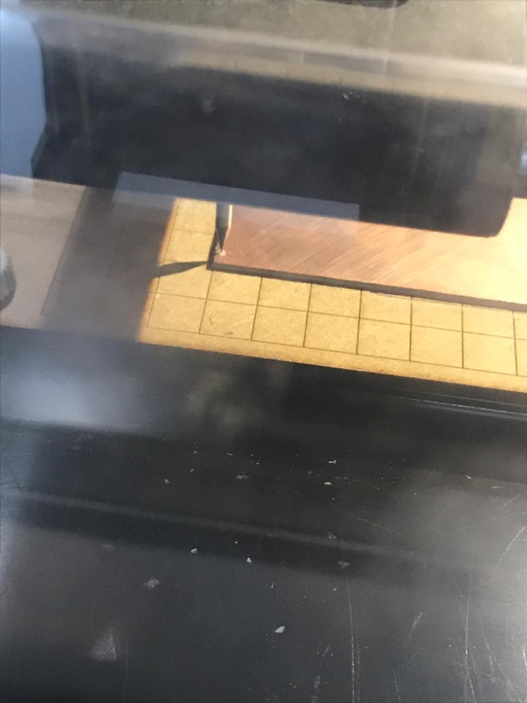
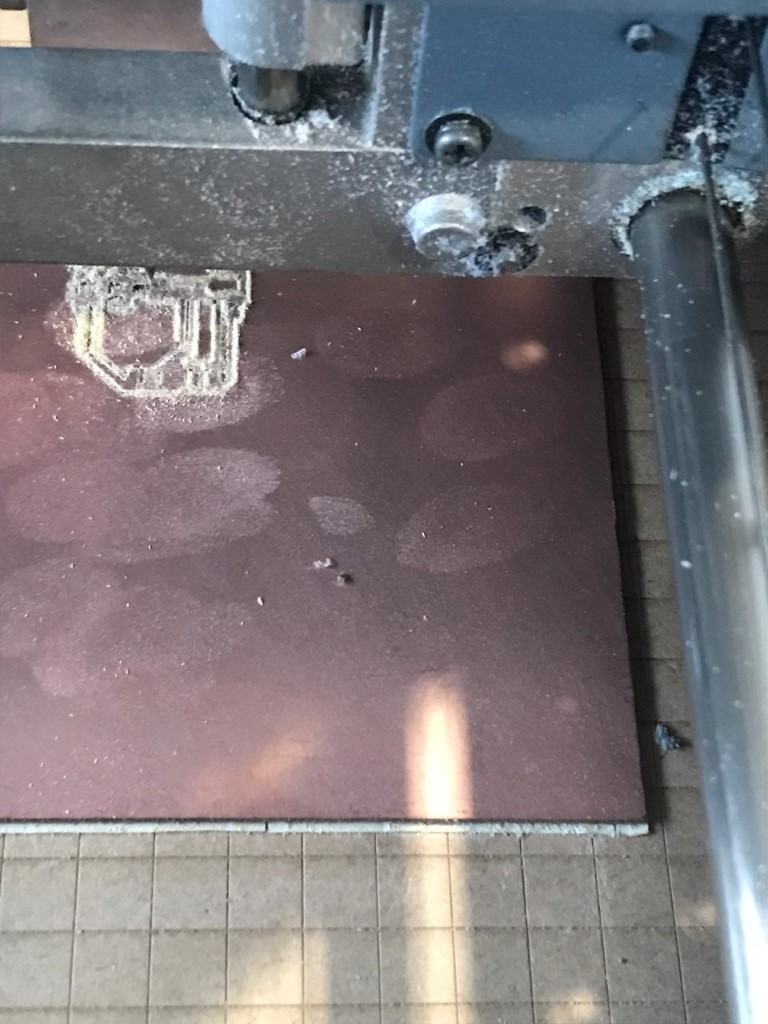
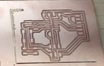
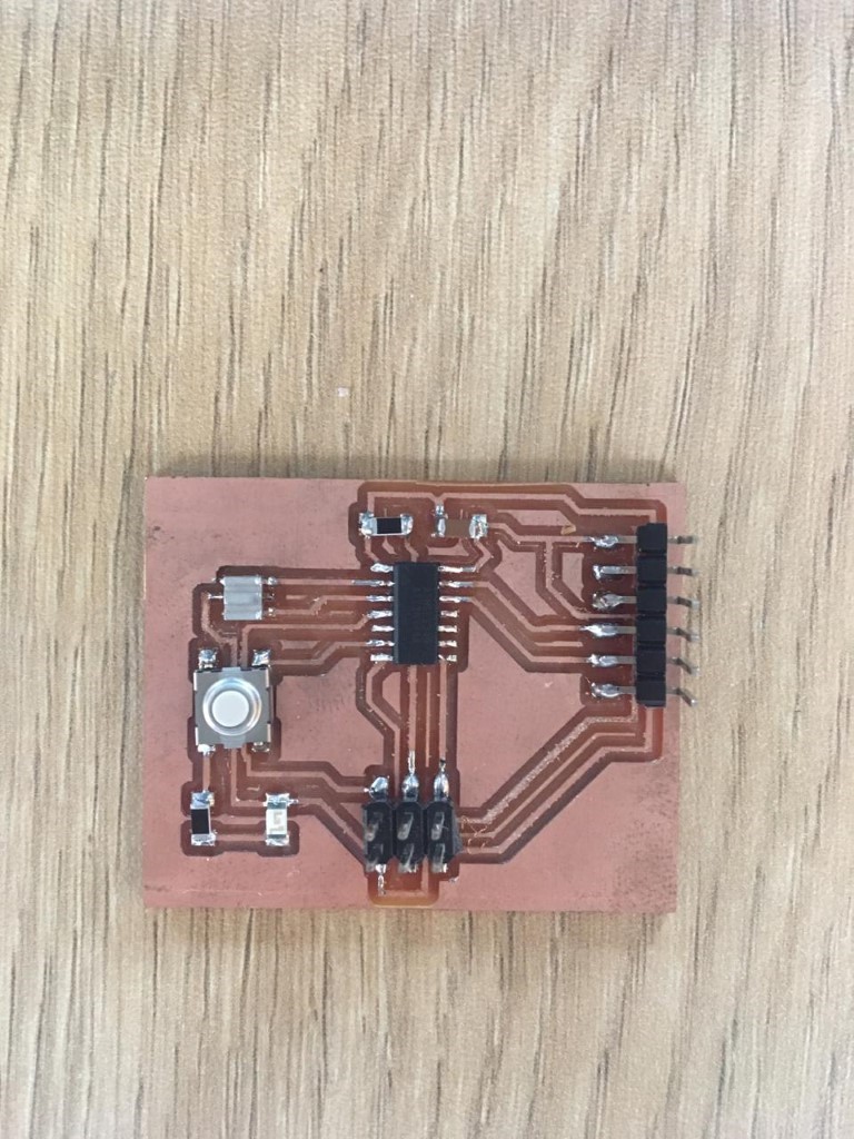
You can see the board. Also You can see the board with external cut
The Fab lab esan provided the components
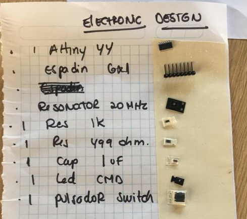
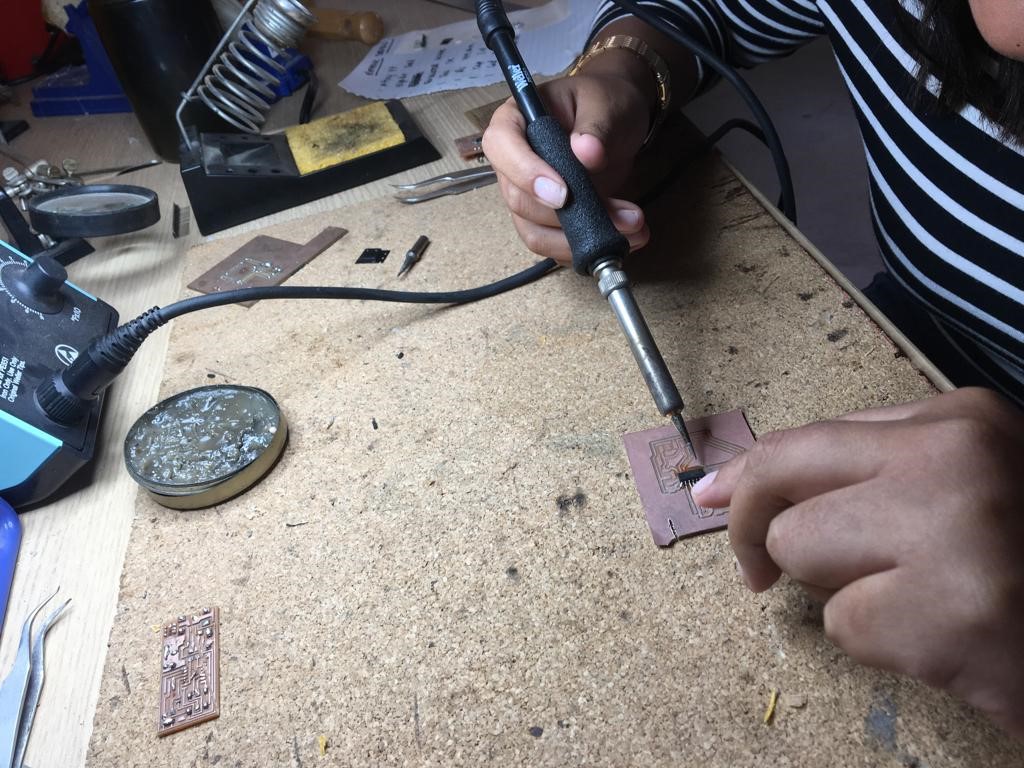
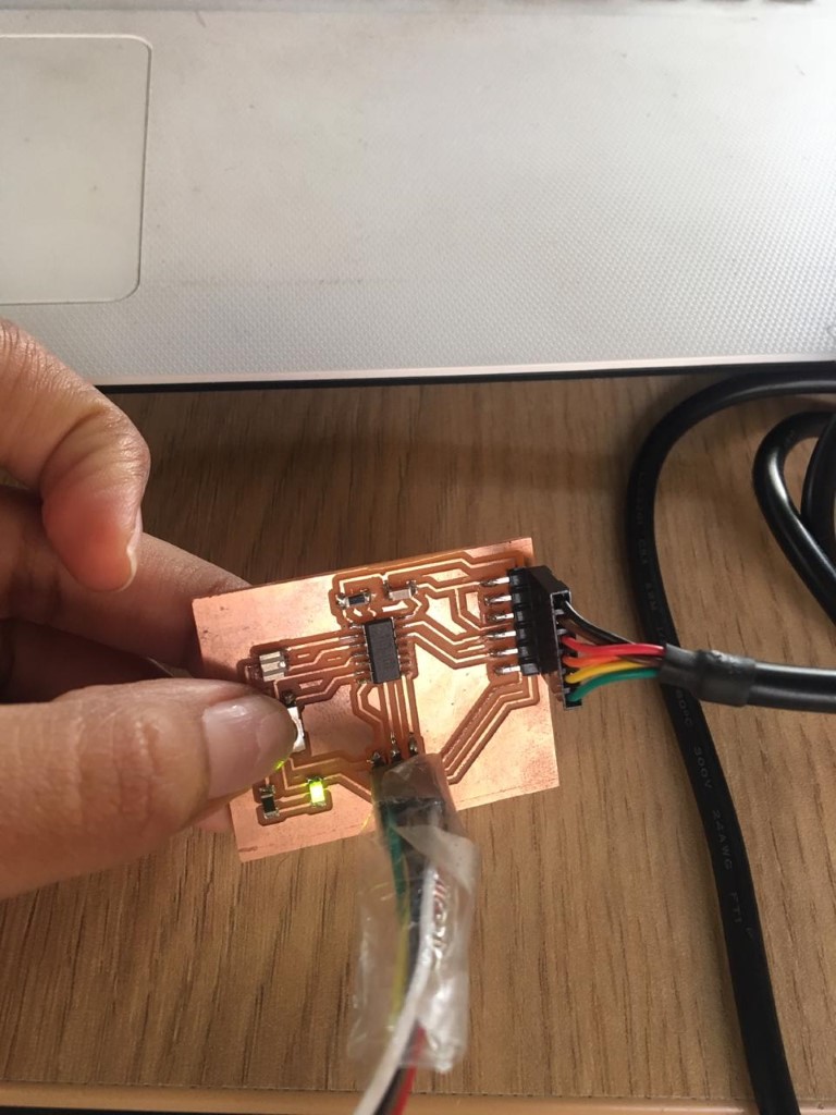
Then, start soldering the components on the plate that has the design paths.
PROGRAMMING
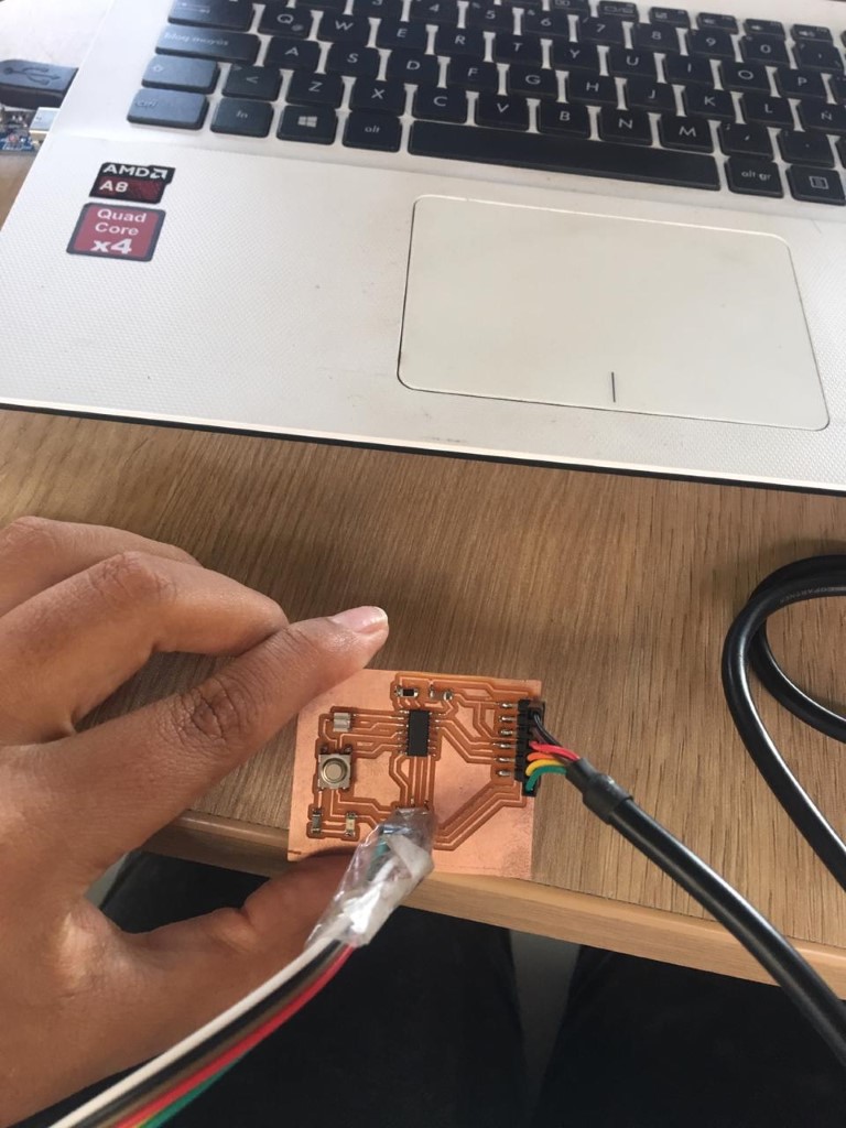
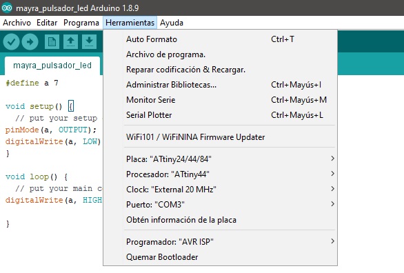
To burn the bootloader, I need to identify the port in wich the FTDI cable was pluged,
then in the tool tab, begin to set the information, board, processor, port.
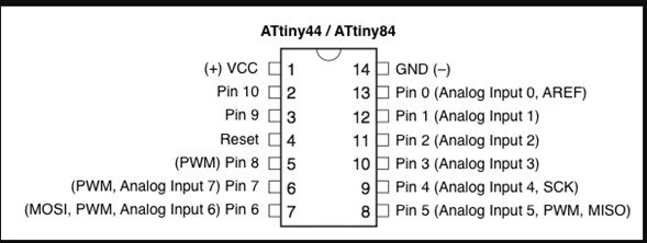
Then I did the programming, which consists of the LED light turning on every time I press the button, also For that I looked for the table of equivalences between the ATtiny and the Arduino,so I can choose the right pins.
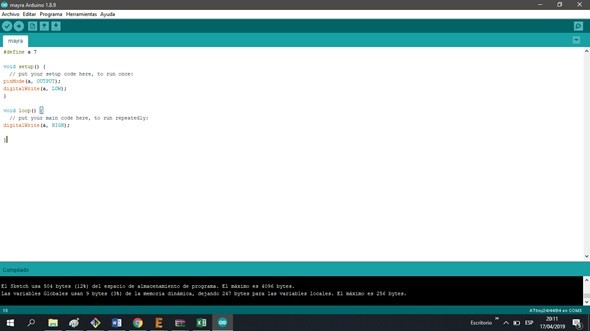
After that I made the code on the Arduin IDE and test the board.
You can see the video, click on the bullet point.
You can download the file by clicking on the bullet.