11. Input devices
All this information is refered to Input Devices class.
Assigment
- Measure something: add a sensor to a microcontroller board that you have designed and read it.
Group Assigment
-Probe an input device’s analog levels and digital signals
Step Response Sensor
Foto del sensor
A Step Response sensor, are input devices that act as a Heavyside Step Function; meaning, a change that goes from 0 to one in a very short period of time.

Capacitive Sensor:
The capacitance of a device is the ratio of the change in an electric charge in a system to the corresponding change in its electric potential 1.
Sometimes you put a dialectric material between the two plates of your capacitor (in the case of this sensor, the conductive vynil). The capacitance of the system will vary in function of the conductivity of the material.
More details on this can be found in the following link.
Datasheet
To understand Neils code for Step Response, anhis is what I learned:
ADMUX - Multiplexer Selection Register
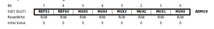
The bits 7-6 Are used to define the reference voltage.
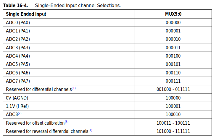
The bits 5-0 Defines wich combination of analog inputs are connected to the ADC. Following this table:
ADCSRA – ADC Control and Status Register A
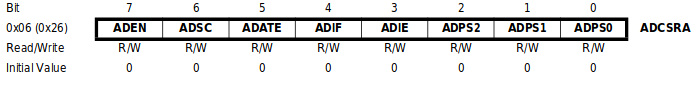
Bit 7 - ADEN: Turn on (1) or off (0) the ADC.
Bit 6 - ADSC: Write 1 to start a conversion, and will turno into 0 when the conversion is finished.
The bits that goes from 5-3 are used in Interrupt protocols, that I didn’t used.
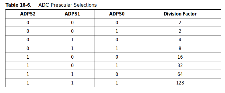
Bits 2-0 - ADC Prescaler Select Bits: Defines the division factor between the system clock frequency and the input clock of the ADC.
This follows this table:
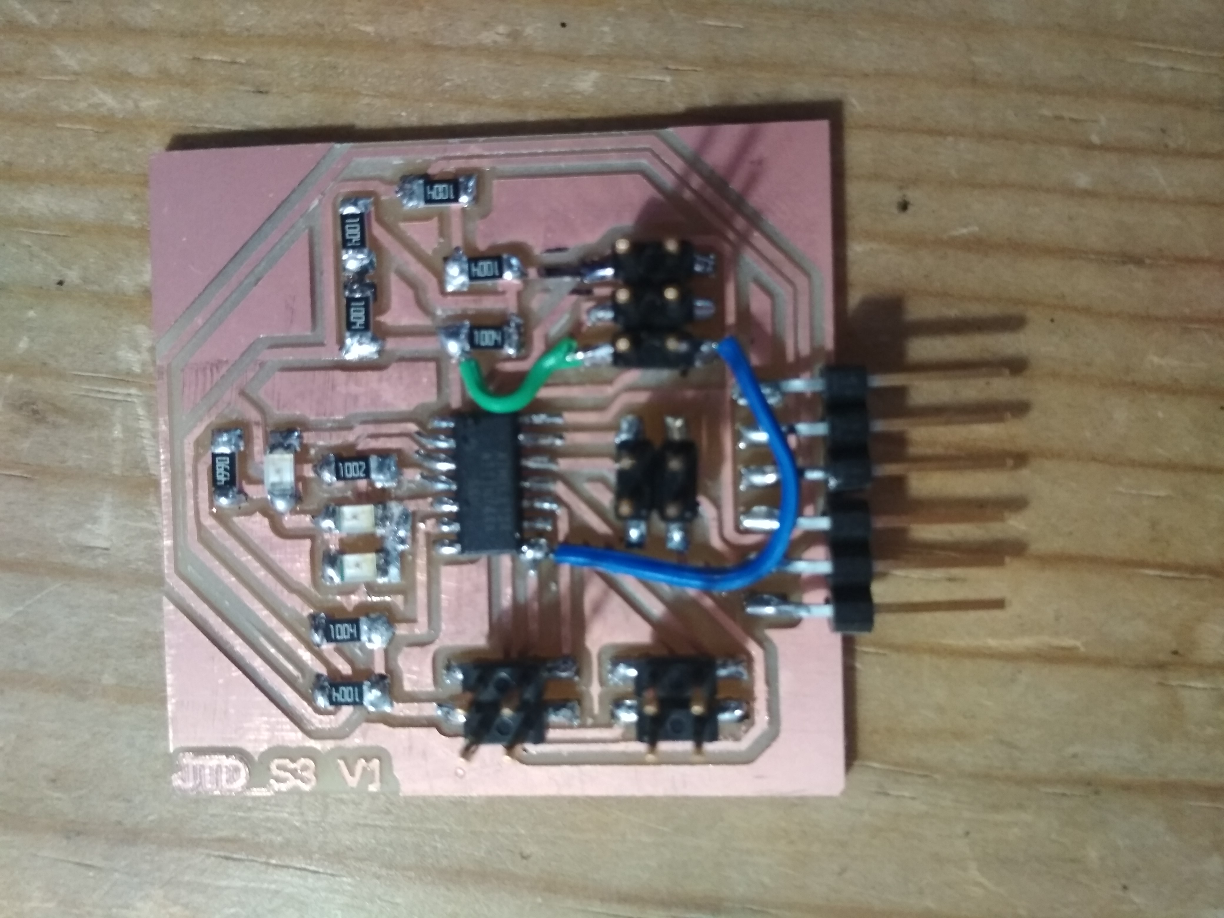
My Board
After testing the concept with Neils board, and being able to see that the sensor responds to the variation of the material that was set between the two cooper plates, I decided to build a board able to read 3 of this sensors, and turning on LEDs when they had water between them.
The board
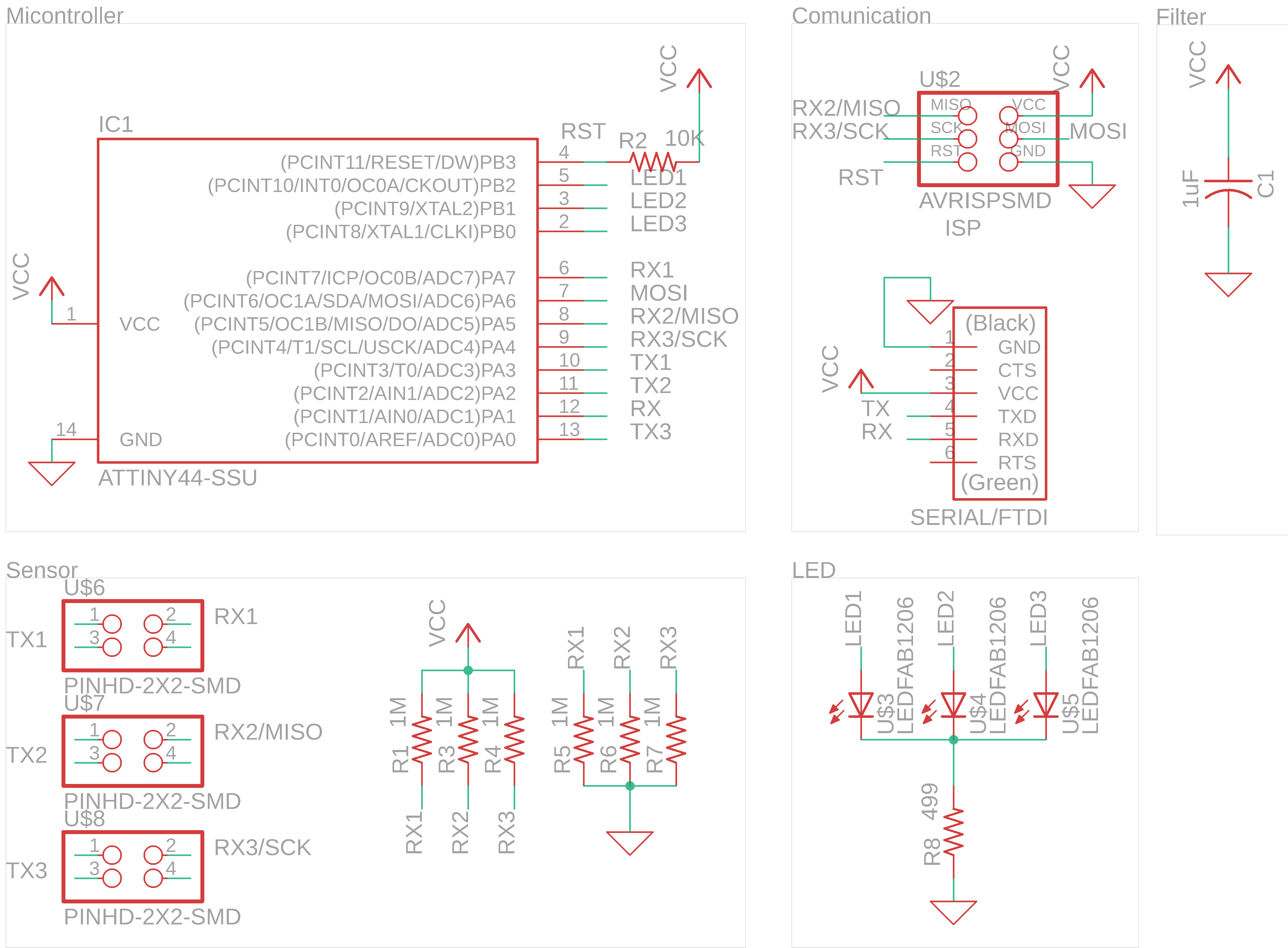
Eagle Schematic:
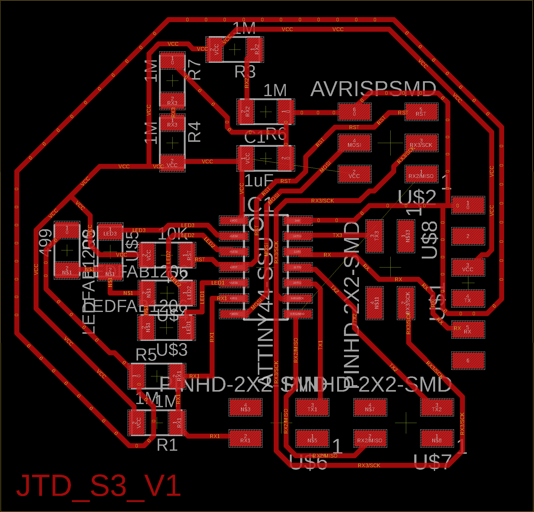
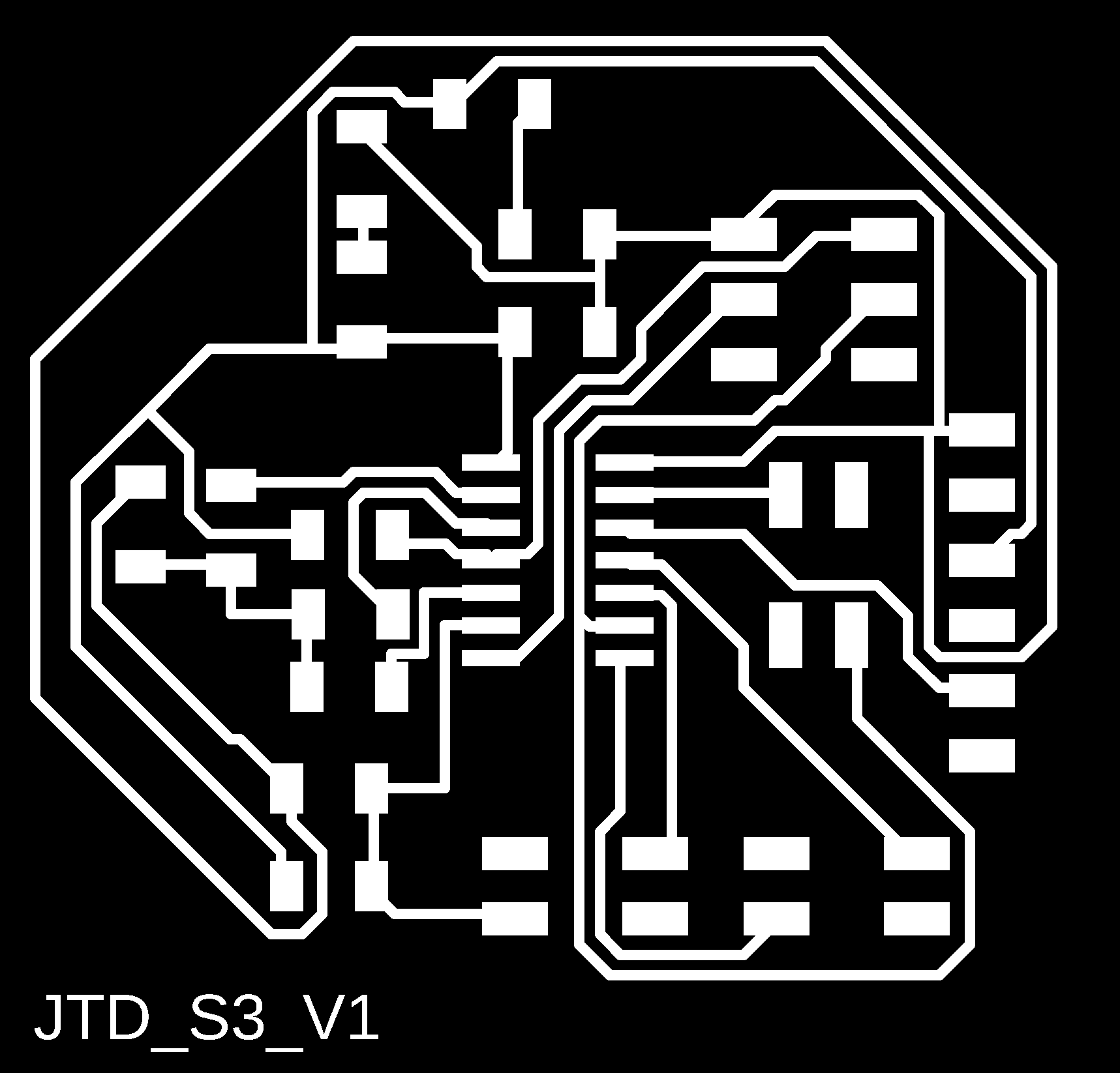
Traces:
Fabrication Files:

The schematic shows that the board consist principally in 3 sensors,each of them with a TX and RX pin, and 3 LEDS, due to the 9 pins I need in order to do this, I had to use a Attiny 44 board.
Components:
- 1x Attiny44
- 1x Resistor 10K
- 3x 4x2 pin header
- 6x Resistor 1M
- 3x LED
- 1x Resistor 499
- 1x 3x2 ISP Pinheader Conector
- 1x 1x6 FTDI Pinheader Conector
- 1x Capacitor 1uF
Code
#include <avr/io.h>
#include <util/delay.h>

#define output(directions,pin) (directions |= pin) // set port direction for output
#define set(port,pin) (port |= pin) // set port pin
#define clear(port,pin) (port &= (~pin)) // clear port pin
#define pin_test(pins,pin) (pins & pin) // test for port pin
#define bit_test(byte,bit) (byte & (1 << bit)) // test for bit set
#define bit_delay_time 102 // bit delay for 9600 with overhead
#define bit_delay() _delay_us(bit_delay_time) // RS232 bit delay
#define half_bit_delay() _delay_us(bit_delay_time/2) // RS232 half bit delay
#define charge_delay_1() _delay_us(1) // charge delay 1
#define charge_delay_2() _delay_us(10) // charge delay 2
#define charge_delay_3() _delay_us(100) // charge delay 3
#define settle_delay() _delay_us(100) // settle delay
#define char_delay() _delay_ms(10) // char delay

#define serial_port PORTA
#define serial_direction DDRA
#define serial_pin_out (1 << PA1)
#define charge_port PORTA
#define charge_direction DDRA
#define charge_pin1 (1 << PA7)
#define charge_pin2 (1 << PA5)
#define charge_pin3 (1<<PA4)


#define Sens1 0b00000011 //TX1@PA3
#define Sens2 0b00000010 //TX2@PA2
#define Sens3 0b00000000 //TX3@PA0
#define trig 970
const int nloop=3;

int Read_Sensor(uint8_t bit, unsigned char pin, unsigned char port){
    ADMUX = bit;
    static unsigned char up_lo, up_hi, down_lo, down_hi;
    int cont,i;
    int sum=0;
    for  (cont=0;cont< nloop; cont++){
    settle_delay();
   set(port, pin);
   charge_delay_1();
    ADCSRA |= (1<<ADSC);
    while (ADCSRA & (1<<ADSC))
      ;
   up_lo = ADCL;
   up_hi = ADCH;
   settle_delay();
   clear(port, pin);
   charge_delay_1();
   ADCSRA |= (1<<ADSC);
   while (ADCSRA & (1<<ADSC))
      ;
   down_lo = ADCL;
   down_hi = ADCH;

   int x = 256*up_hi+up_lo;
   int y=256*down_hi+down_lo;
   int z= x+(1023-y);
   sum+=z;
    }
    sum=sum/nloop;
   return sum;

}

void put_char(volatile unsigned char *port, unsigned char pin, char txchar) {
   //
   // send character in txchar on port pin
   //    assumes line driver (inverts bits)
   //
   // start bit
   //
   clear(*port,pin);
   bit_delay();
   //
   // unrolled loop to write data bits
   //
   if bit_test(txchar,0)
      set(*port,pin);
   else
      clear(*port,pin);
   bit_delay();
   if bit_test(txchar,1)
      set(*port,pin);
   else
      clear(*port,pin);
   bit_delay();
   if bit_test(txchar,2)
      set(*port,pin);
   else
      clear(*port,pin);
   bit_delay();
   if bit_test(txchar,3)
      set(*port,pin);
   else
      clear(*port,pin);
   bit_delay();
   if bit_test(txchar,4)
      set(*port,pin);
   else
      clear(*port,pin);
   bit_delay();
   if bit_test(txchar,5)
      set(*port,pin);
   else
      clear(*port,pin);
   bit_delay();
   if bit_test(txchar,6)
      set(*port,pin);
   else
      clear(*port,pin);
   bit_delay();
   if bit_test(txchar,7)
      set(*port,pin);
   else
      clear(*port,pin);
   bit_delay();
   //
   // stop bit
   //
   set(*port,pin);
   bit_delay();
   //
   // char delay
   //
   bit_delay();
   }

int main (void){
 // Define clock devider
 CLKPR = (1<<CLKPCE);
 CLKPR = (0 << CLKPS3) | (0 << CLKPS2) | (0 << CLKPS1) | (0 << CLKPS0);

 //Set prescaler to 128
 ADCSRA = (1 << ADEN); // enable
 ADCSRA = (1<<ADEN)|(1<<ADPS2)|(1<<ADPS1)|(1<<ADPS0);
   // initialize output pins
   set(serial_port, serial_pin_out);
   output(serial_direction, serial_pin_out);

   DDRB = 0xFF;
   output(charge_direction, charge_pin1);
   output(charge_direction, charge_pin2);
   output(charge_direction, charge_pin3);

while(1){
   int z= Read_Sensor(Sens2,  charge_pin2, charge_port);//abajo
   if (z>trig){
      PORTB &= ~(1<<PB2); //PORTx |=(the value<<number positions)
   }
   else{
      PORTB |= (1<<PB2); //PORTx |=(the value<<number positions)
   }
   int x= Read_Sensor(Sens3,  charge_pin3, charge_port);//medio
   if (x>trig-10){
      PORTB &= ~(1<<PB1); //PORTx |=(the value<<number positions)
   }
   else{
      PORTB |= (1<<PB1); //PORTx |=(the value<<number positions)
   }
    int y= Read_Sensor(Sens1,  charge_pin1, charge_port);//arriba
   if (y>trig){
      PORTB &= ~(1<<PB0); //PORTx |=(the value<<number positions)
   }
   else{
      PORTB |= (1<<PB0); //PORTx |=(the value<<number positions)
   }
}
}
I started from the basis of Neild code to program a step sensor; I added the capacity of reading 3 of them; and also turning on and of some LEDS as a function of a trigger.
First Test - Hand Contact
As a first test, I just touched the two sensors, to make a conection between both of them and turn on the LEDS and check that everything was working.
You cas see the results in the following video:
Water Test
The following experiment was to use the sensor as a water detector level in a syringe; the results can bee seen in the following video:
José Tomás Domínguez (Joseto) on Vimeo.
Conclusion
- Even though the sensors where able to read, the variations in the capacitance due to the enviroment noise where bigger, so the sensors trigger themselves. This made them not so trustfull.
- Maybe isolating the device electrically from the enviroment is a solution, this will be tested in the following weeks.
- I think maibe a better solution is to measure the position of the syringe seal, with a Hall Efect sensor and a magnet in its inside.
Step Sensor
Finally, to test if the sensor worked, I tested without the water and syringe concept; and just used a more typical step sensor usage. Testing them as touch botons. As you can see in the video, it works perfectly.
José Tomás Domínguez (Joseto) on Vimeo.