4. Computer controlled cutting
All this information is refered to Computer-control cutting class.
Assigment
- Cut something on the vinylcutter
- Design, lasercut, and document a parametric press-fit construction kit.
Group Assigment
- Characterize your lasercutter, making test part(s) that vary cutting settings and dimensions.
- Determine the machines kerf.
Machines
Vinyl Cutter Roland GX4
 Image from Roland oficial webpage.
Key Parameters
- Force
- Speed
- Cut Depth
Materials
- Vinyl
- Transfer Adhesive
- Masking Tape
Laser Cutter
 Image from Epilog oficial webpage.
Key Parameters
- Laser Power
- Speed
- Rate (Laser Frecuency)
Materials
- Polywood
- MDF
- Acrylic
Group Assigment
Research
Kerf is defined as the width of material that is removed by a cutting process. It was originally used to describe how much wood was removed by a saw, because the teeth on a saw are bent to the side, so that they remove more material than the width of the saw blade itself, preventing the blade from getting stuck in the wood.
When talking about CNC shape cutting with typical cutting processes, kerf is the width of material that the process removes as it cuts through the plate.
Over the years I’ve heard some people use the term when referring to the angle on the edge of the part, but that would be an incorrect use of the word. The “cut angle” on the edge of the part makes measuring the kerf width sorta tricky, but for consistency, the word “kerf” should only be used when talking about the actual cut width.
Experiment
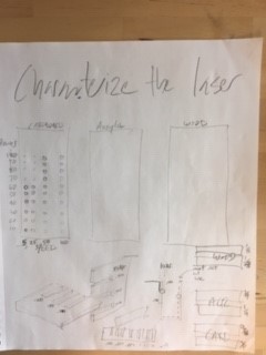
The idea was to make a 2 sloted boards with a small variation in every slot length, incrementing from 3.25 - 4.25 [mm]. After they were cutted we measured every slot real size to determine the machines kerf.
Results
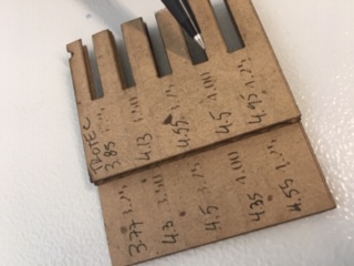
In the figure you can see the sloted boards, with the real cuts length aside. This values are shown in the following table:
| Sloted Board | Theoretical Length | Real Length | Delta |
| 1 | 3.25 | 3.85 | 0.60 |
| 1 | 3.5 | 4.13 | 0.63 |
| 1 | 3.75 | 4.55 | 0.80 |
| 1 | 4.00 | 4.50 | 0.50 |
| 1 | 4.25 | 4.95 | 0.70 |
| 2 | 3.25 | 3.77 | 0.52 |
| 2 | 3.50 | 4.30 | 0.80 |
| 2 | 3.75 | 4.50 | 0.75 |
| 2 | 4.00 | 4.35 | 0.35 |
| 2 | 4.25 | 4.55 | 0.30 |
| Average Kerf | 0.60 | ||
| Estandard Deviation | 0.18 |
From now on, the work is going to be developed thinking on a kerf of 0.60 [mm].
We also tested the slots that better fit in order to make joints, key in the personal assigment for this week:
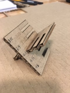
As we can see, for a 4 [mm] thikness heavyduty cardboard, the best slot to make joints is the 4.00 theorical.
Problems
In the lab, the got 2 laser cutter (insertar modelos). The Trotec Speedy 400 doesn’t have an air system to stop flames when you are cutting organic materials.
José Tomás Domínguez (Joseto) on Vimeo.
Vinyl Cutting
To get an image into a vinyl cutter you have to transform the image format into .png, although this format is comonly used to have pictures without color in the bacground, they have to have color, in the backgorung, and in its countour.
You have to define 2 key parameters; force, speed. I had lots of problems getting into the correct force.
First Cut:
I got problems with the the result, because the image was too big. I changed the DPI from 300 (952.5x352.778 [mm]) to 72 (228x84.667[mm]).
Second Cut:
I tried: - Force: 50[g] - Speed: 20[cm/s]
But it didn’t cut trhough.
Third Cut:
I tried: - Force: 60[g] - Speed: 20[cm/s]
When I cuold cut through, this is the result:
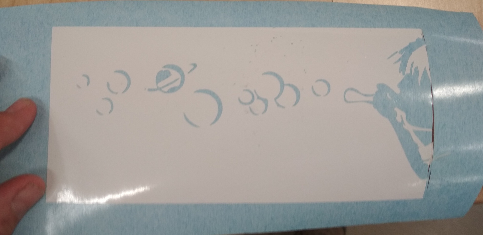
To transfer the vinyl into another surface, you have to use transfer tape:
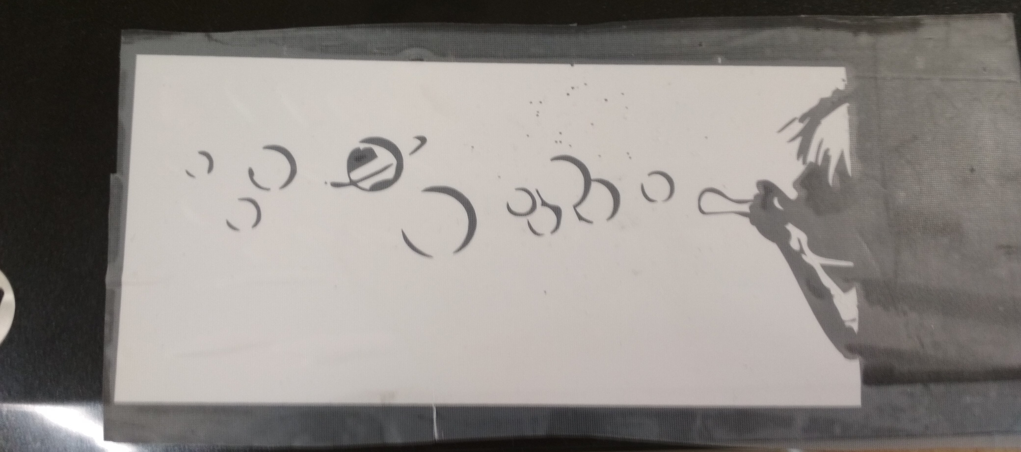
Finally you reomve the transfer tape, getting the image sticked onto the new surface:
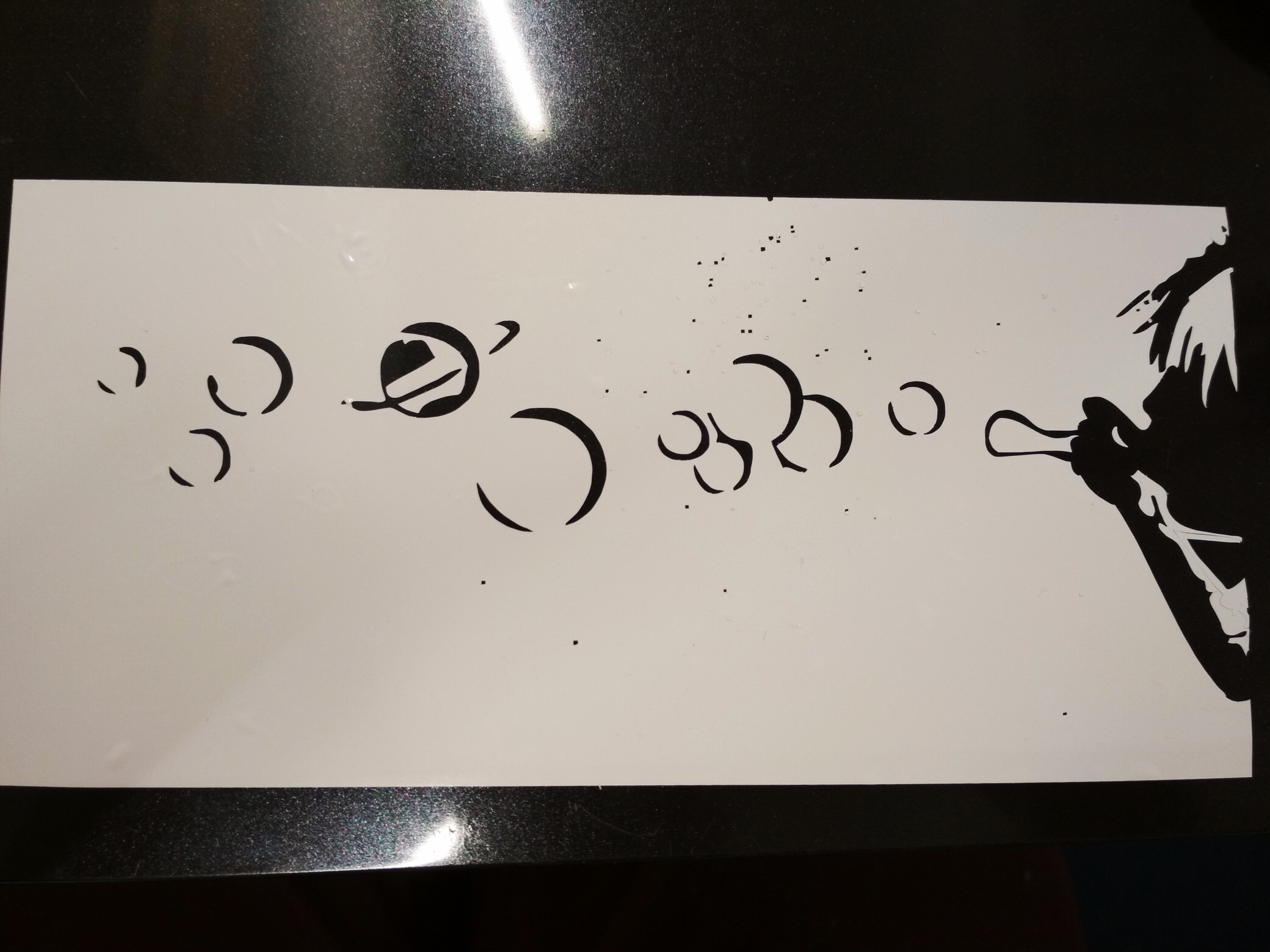
This is the original image for references:

Parametric Design
For this week assigment we needed to lasser cut a parametric design.
As I tested different Computer aieded design software in weeks 3 assigment, I concluded that Rhino-Grasshoper was a good software for natural forms and design developments, where the stetic part was its fundamental issue. Fusion 360 was a better software for mechanical design, as it managed better the assembly of diferent parts.
I decided to develope parametric designs in both softwares.
Fusion 360
Setting the parameters
In order to set a series of parameteres using Fusion 360, you have to go Modify ==> Change Parameters.
I made a table of diferent Key Parameters for my Drone base:
| Name | Unit | Expression |
| Height | mm | 80 mm |
| Length | mm | 55 mm |
| WingLength | mm | 80 mm |
| WingRadius | mm | 60 mm |
| BaseArc | mm | 20 mm |
| MotorRadius | mm | 30 mm |
| MotorPosition | mm | 20 mm |
| MaterialThikness | mm | 5 mm |
| SlotPosition | mm | 20 mm |
| SlotLength | mm | 80 mm |
3D Model
Here I am going to present what I got from Fusion, a Drone Base with the posibility of modifying different parameters, so you can fit the mechanical and electronic parts.
The Result
Laser cutting allows to dimension our design, and solve some critical questions.
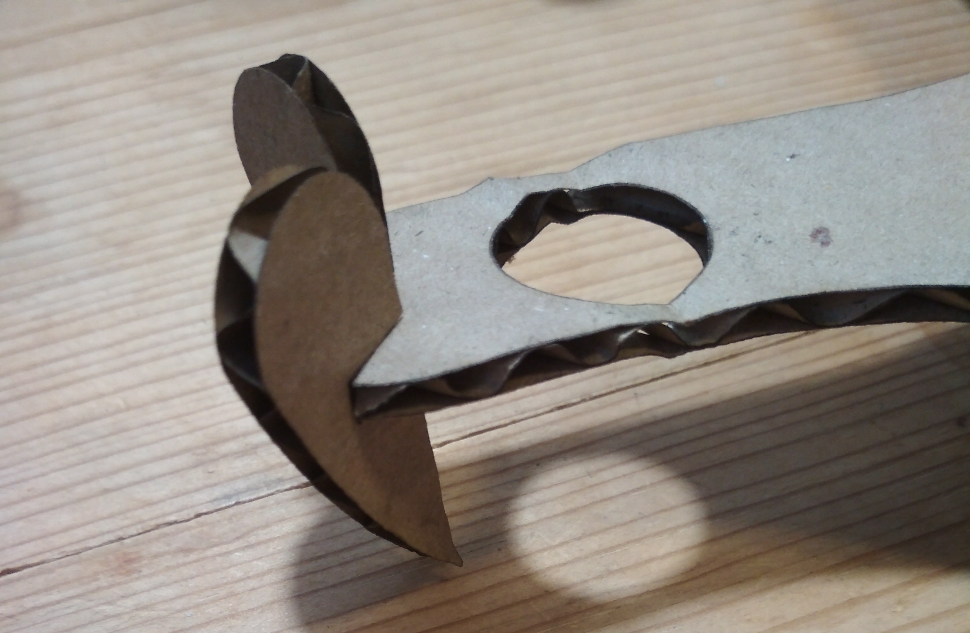
As we can see in the image bellow there is a critical zone in the design.
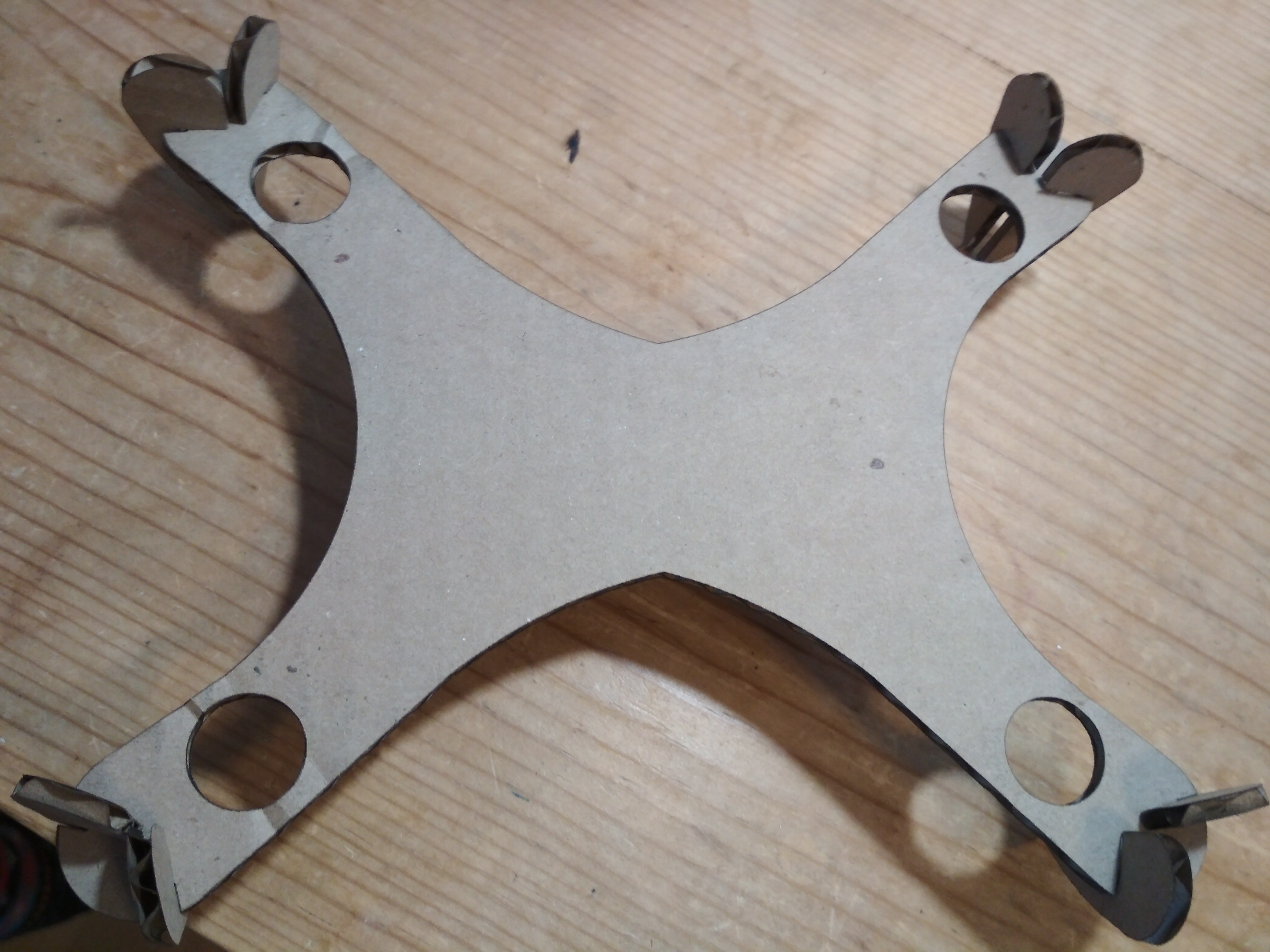
Zooming the laser cut drone base, we can notice an specific zone that deflects due to the thikness of the design.
Useful Links
Rhino-Grasshoper
The idea is to build a Grasshopper code that allows the user to get any surface as a Berp into Grasshopper, and get a parametric design as an output.
In order to do this, I downloaded a 3D Model from Free3D.
Key Concepts
As I am new into the world of Rhino-Grasshopper, ther are some new concepts or functions I would write during my documentation.
- Rebuild: I allows the user to rebuild an object after it has been manipulated.
- SoftEditSrf: It is used when the user wants to modify an specific part of the surface, generating a smooth modification through all of it.
- DupBorder: It duplicates the border of the surface we are wroking with.
- CrossReference: It would match each component of one list, to the refered one in the other list, the 0 of list A with the 0 of lista B, the 1 with the 1… the n with the n.
- Bake: Combines the objects texture and decals into a single image file. This is key when you are working with renders.
- Layer: Layers is a way to manipulate groups of objects.
Every name is linked to a more detail explanation of it functions in a Grasshopper specific site.
Uploading a not .3dm 3D Model to Rhino
Uploading a 3D model with a different format into Rhino wasn’t that easy. At the begining the software didn’t recognize the mesh, so I wasn’t able to transform it into a solid.
In case you have the same problem, just follow this simple steps:
1.- Apply Mesh > Mesh Repair > Fill Holes to all component meshes.
2.- Apply Mesh > Mesh Repair > Unify Normals to all component meshes.
3.- Join all component meshes with Mesh > Mesh Boolean > Union.
4.- Enter “MeshtoNURB” at the command line to convert mesh to solid.
5.- Check that the result is a closed solid polysurface with the “What” command.
Parametrizing the 3D Model
To parametrice the model, you have to build a Grasshopper sketch that would allow you to decompose the solid into layers that would fit each other, to allow you build it through a laser cutter.
To learn How to do this, I followed the intructions given in this tutorial.
For Grasshopper users, who want to use my code, you can downloaded from the following link:
With this code you have the following inputs:
- Brep
- Number of slices in X axis
- Number of slices in Y axis
- Thickness of the material
And you’ll get an sliced parametric model as an output.
Unlikely, it isn’t working perfect in this moment, but it helped me a lot to see how to decontruct a circle and make a Press-Fit Construction Kit.
Press-Fit Contruction Kit
I decided to work with modules of circles that can grow indefinitely in a plane.
Here you can see the 3 principal modular parts that allows the user to build the circle strcuture:
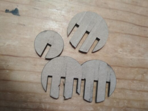
This parts where designed usign Grasshopper, and the idea came from the decontruction of a sphere using the code posted before. Here you can download the code for the Press-Fit Spheres, where you can modify the diferent parts radius, material thikness and kerf.
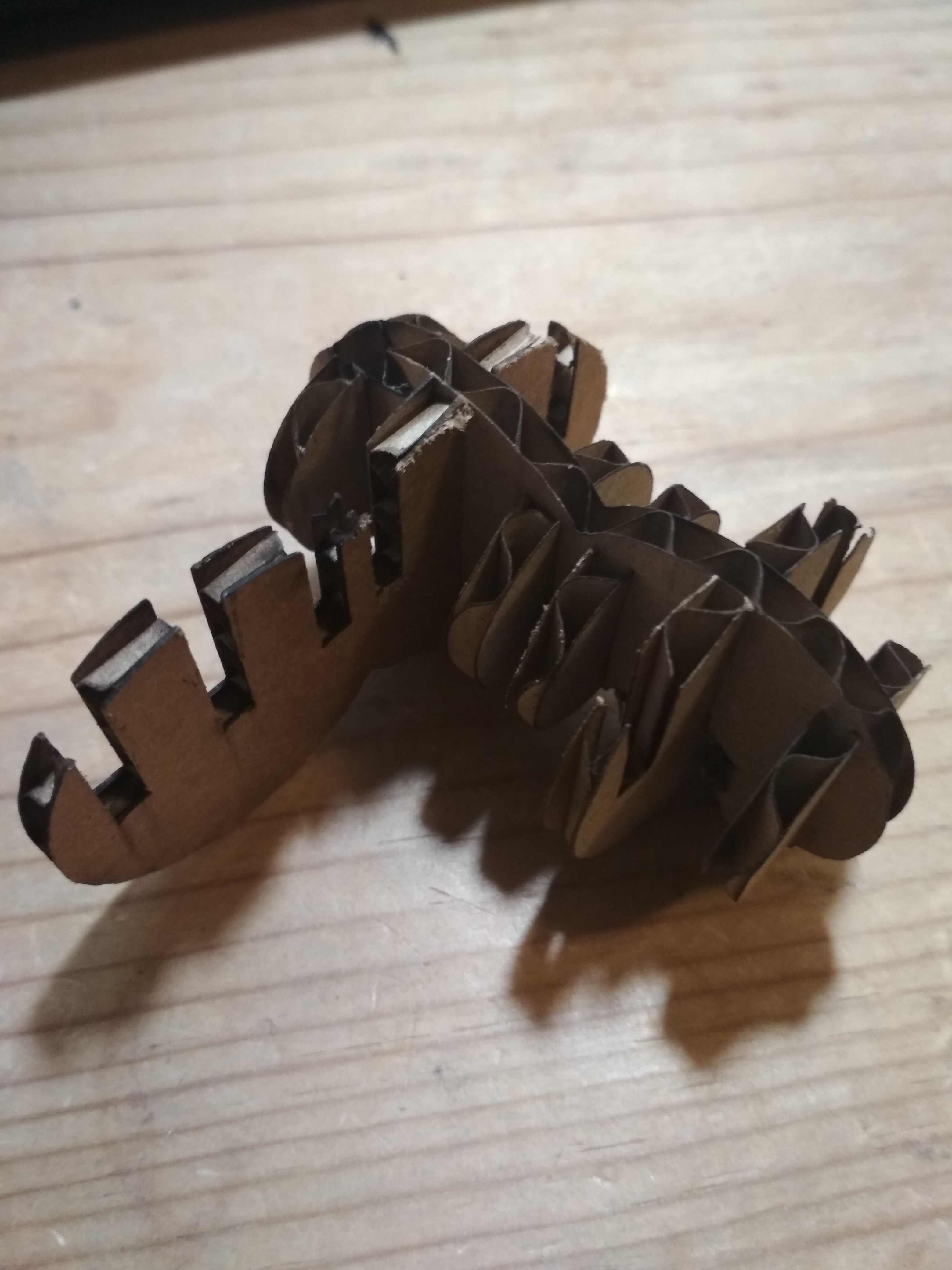
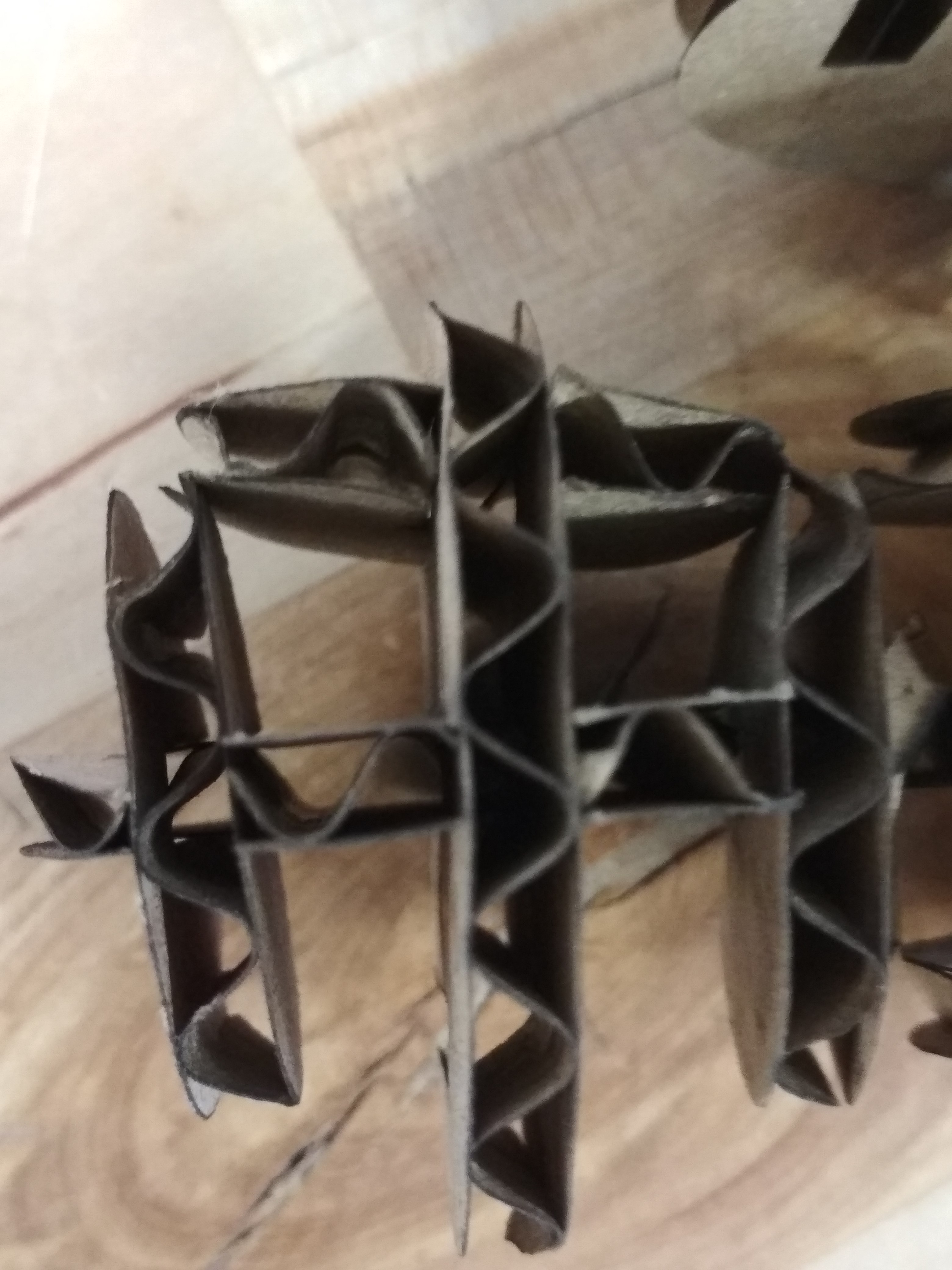
In the following figure, you can see how the 3 modules fit each other to biuld a bigger strcture:
Of course, theres no digital fabrication without problems, my first design had one of the circles to big, so they interfered each other:
As the code is parametric, I just cahnged the little circles radius, and got my final structure: