5. Electronics production
All this information is referred to Electronics production class.
Assignment
- Make an in-circuit programmer by milling the PCB.
Group Assignment
- Characterize the design rules for your PCB production process
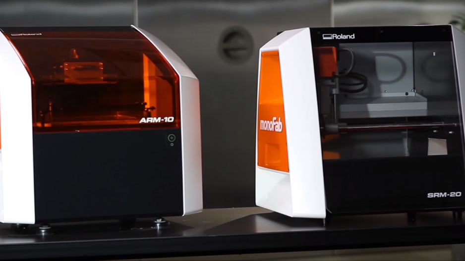
Machines
Roland MonoFab SRM-20
Key Parameters
- Tool Diameter
- Cut Depth
- Max Depth
- Offset number
- Speed
- Working 0
Materials
- PCB circuit board FR1
- Machinable Wax (Molding and Casting)
Vinyl Cutter Roland GX4

Key Parameters
- Force
- Speed
- Cut Depth
Materials
- Vinyl
- Transfer Adhesive
- Masking Tap
- Copper Adhesive
Group Assignment
For the group assignment we had to characterize the machine, to know the limits it has at the moment of producing electronics.
The Process
This is the design we are going to use for the process; as you can see it allows us to study the minimum thickness of a line, or cable, that the machine is able to cut, also it allows to check the maximum slot thickness you can do between 2 cables.

In order to do this we used a 1/64 inches end mill (Right).
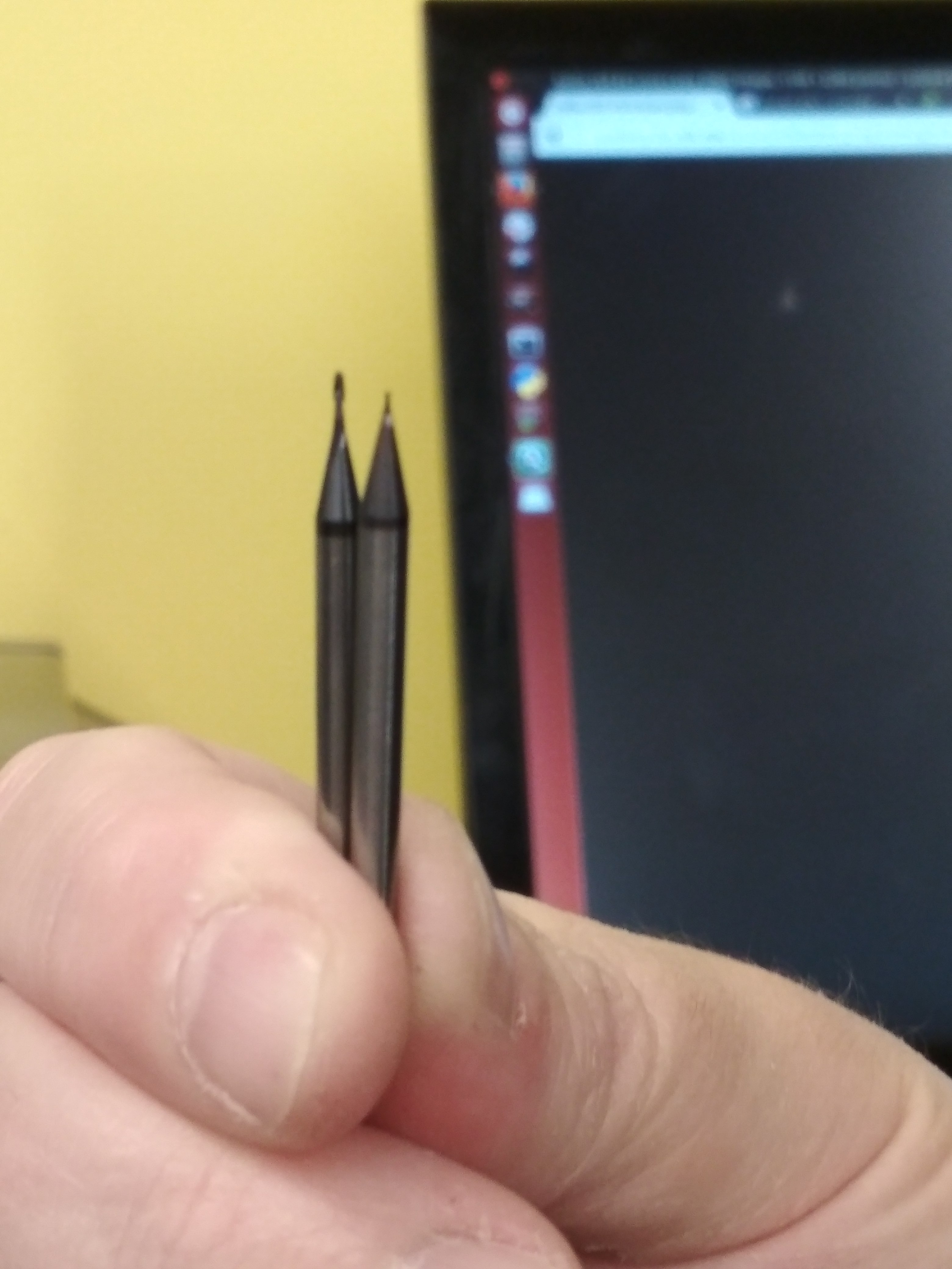
Then we had to cut the interior:

This process was done with a 1/32 inches end mill and used 3 step passes.
To program the machine we used Mods, a cloud program developed in MIT CBA lab, that allows users to control different machines through the same software.
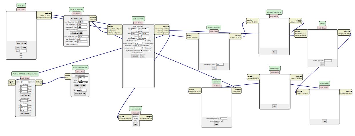
Steps:
1.- Upload the .png file.
2.- Check some parameters, tool diameter, cut depth, max depth, offset number.
3.- Select Traces or cutline depending on the file.
4.- Zeroing
5.- Zeroing Z axis, this is going to get a more profound explanation because it needs more work.
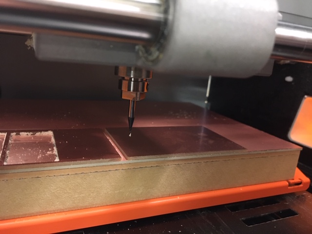
In the following image you can see the end mill in its 0 position for the axis X and Y.
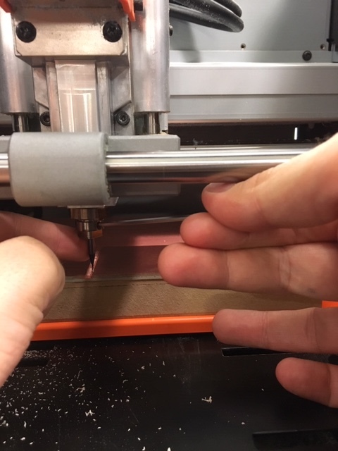
In order to zero the Z axis, you release the end mill and kindly drop it until it touches the PCB.
The Result
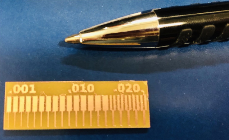
This is the result we have gotten, we can see that the machine is able to cut lines of a thickness of 0.001 inches. Meanwhile it isn’t able to cut slots that little, the minimum thickness it could cut was 0.016 inches.
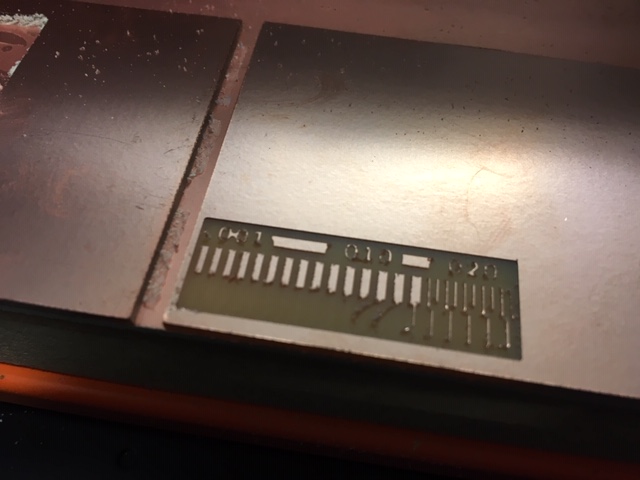
Problems
The first time we cut the traces, we chose the wrong end mill, installing the 1/32 for the traces, instead of the 1/64, so this is what’s we got:
Fab ISP
The following assignment was to program a Fab ISP.
Fab ISP is a version of the AVR ISP programmer/board that can easily be produced in a Fab Lab with a milling machine.
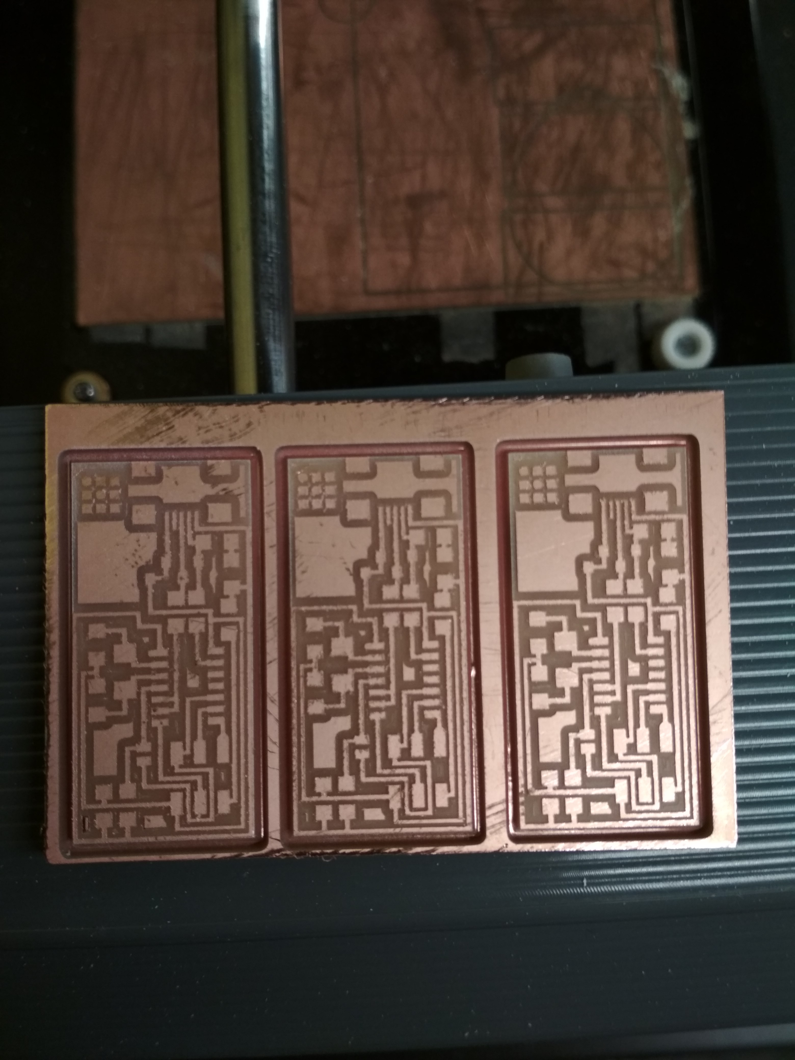
Milling
I’m not going to explain the process of milling, since I already explained, so, I just going to show the results:
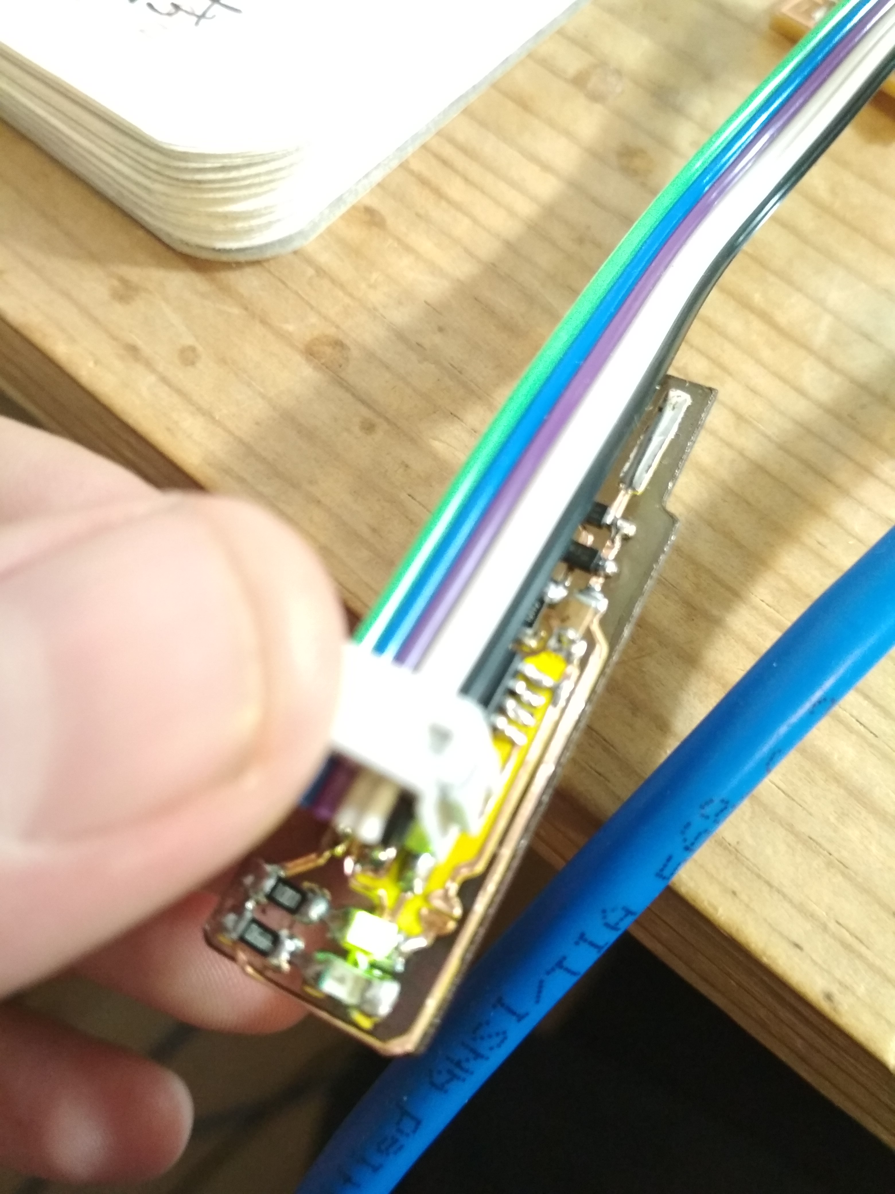
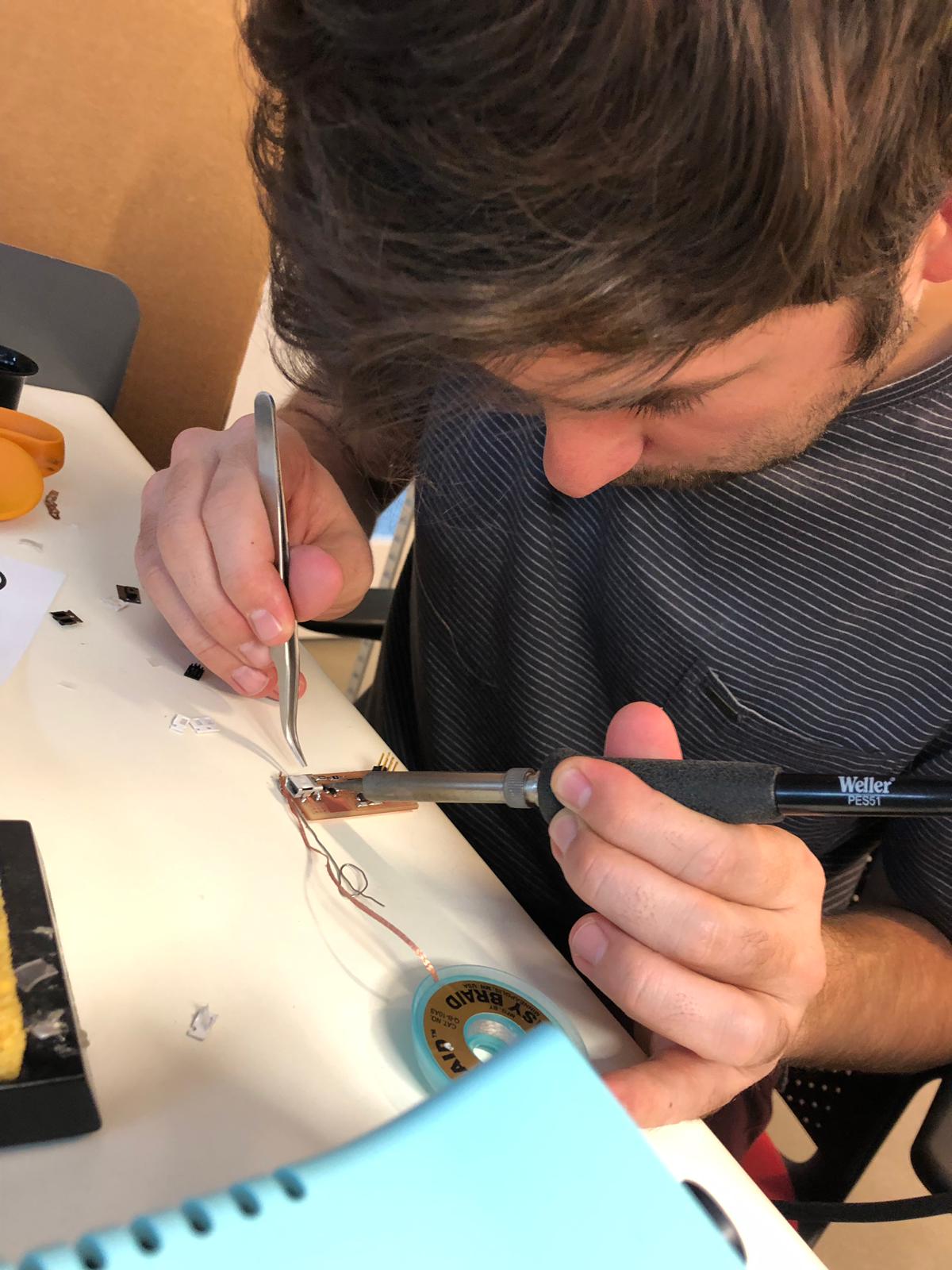
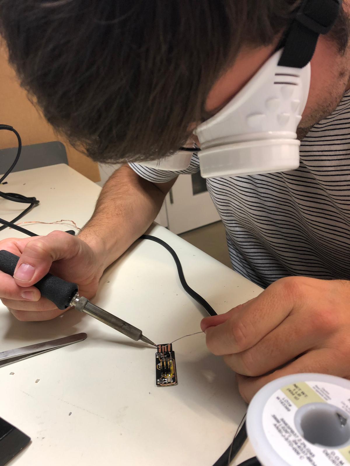
Soldering
I had experience in soldering, but I had never worked with SMD components, which make all the process harder, due to the small spaces you’ve got.
You can see the concertation:
Materials
- Solder
- Solder station
- Fume extractor
- Electric solder gun
- Braid
- Solder sucker
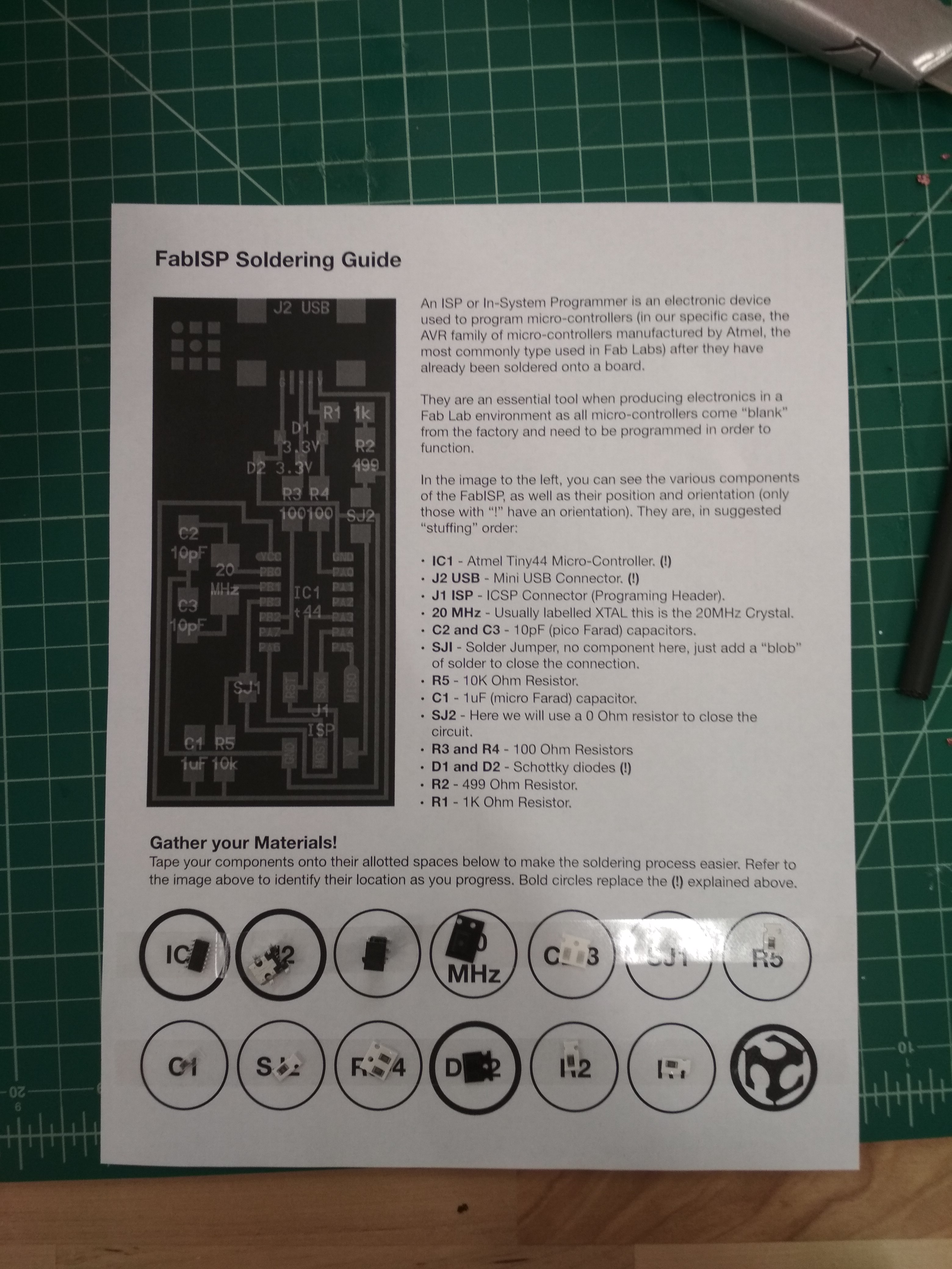
To make the solder process easier, our instructor print this easy guide, so we didn’t get confuse and we could advance quickly:
I had to solder 2 boards because the first one didn’t worked. I tried a lot to find the mistake but wasn’t able.
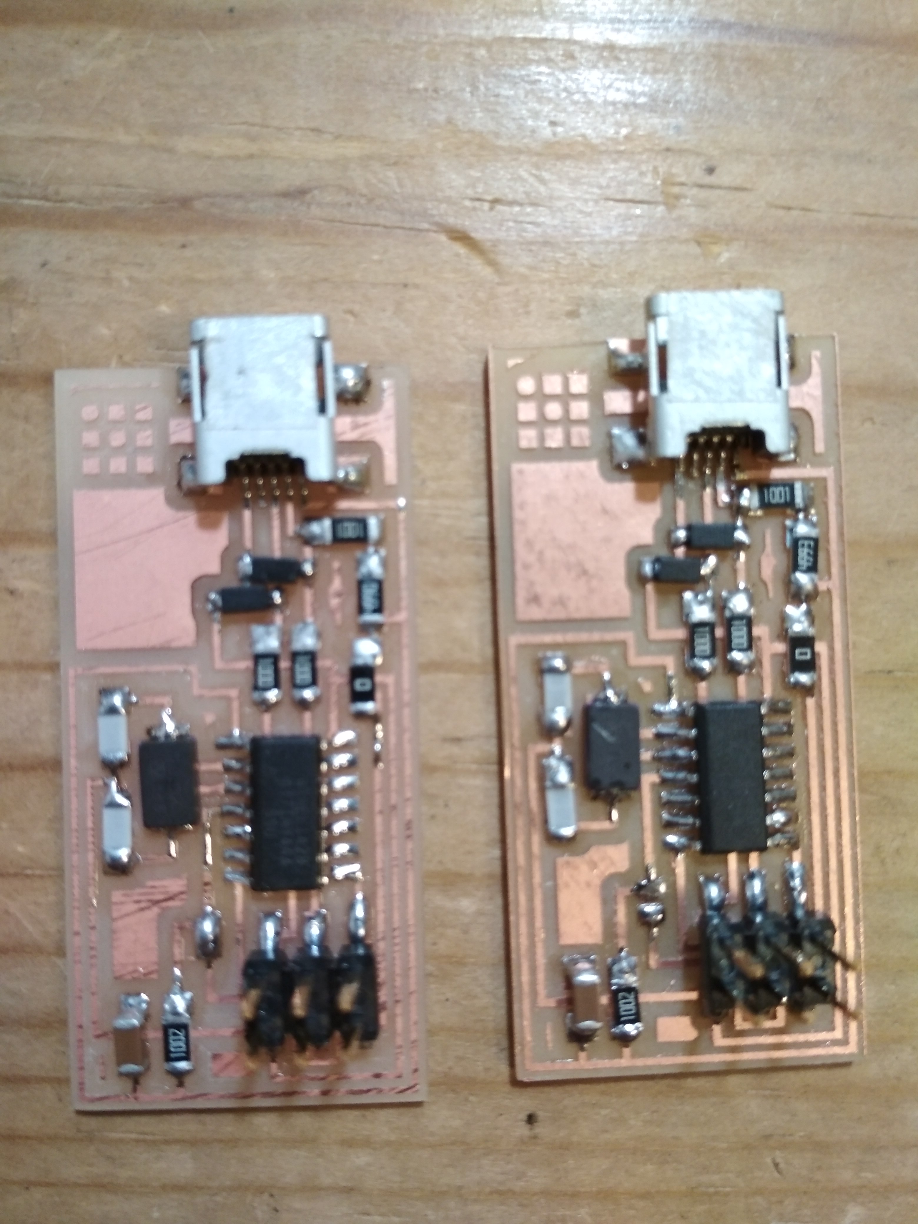
Maybe you’re able to see what’s wrong, or just identify which one isn’t working!
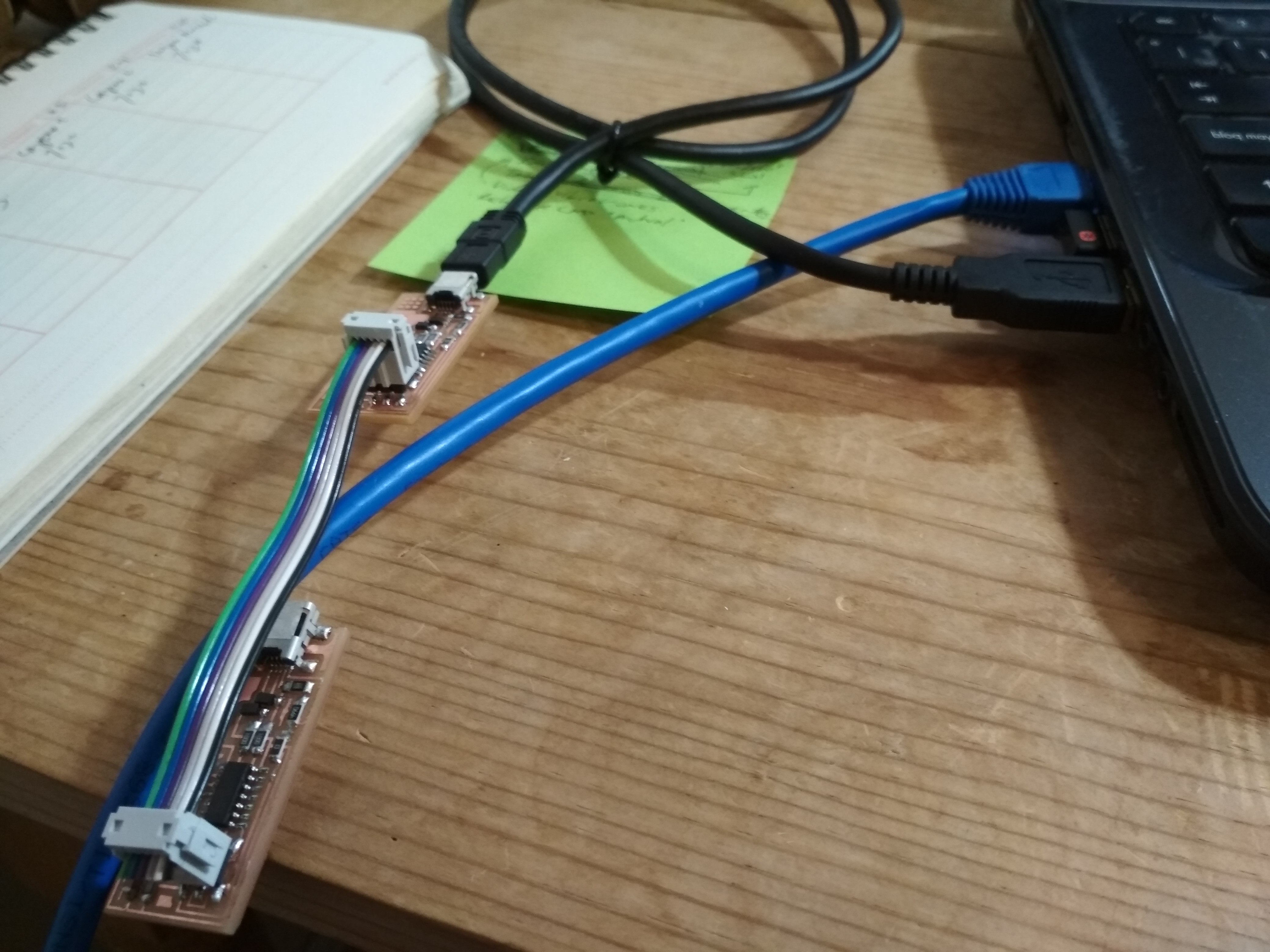
Programing the Fab ISP
This is the hardest part, because you have to be prepared to check if you ISP is working (remember that my first ISP didn’t, so frustrating!).
Materials:
- Programer ISP
- 6 cable connector
- USB cable
- Your ISP already solder
Programing Process
This whole process is explained in the FabAcademy_Tutorials.
If your circuit works you will receive the following massage:
Last login: Tue Feb 19 15:03:13 on ttys000

MacBook-de-Calendula:~ calendula$ cd desktop

MacBook-de-Calendula:desktop calendula$ cd fabISP_mac.0.8.2_firmware

MacBook-de-Calendula:fabISP_mac.0.8.2_firmware calendula$ make clean

rm -f main.hex main.lst main.obj main.cof main.list main.map main.eep.hex main.elf *.o usbdrv/*.o main.s usbdrv/oddebug.s usbdrv/usbdrv.s

MacBook-de-Calendula:fabISP_mac.0.8.2_firmware calendula$ make hex

avr-gcc -Wall -Os -DF_CPU=20000000  -Iusbdrv -I. -DDEBUG_LEVEL=0 -mmcu=attiny44 -c usbdrv/usbdrv.c -o usbdrv/usbdrv.o

avr-gcc -Wall -Os -DF_CPU=20000000  -Iusbdrv -I. -DDEBUG_LEVEL=0 -mmcu=attiny44 -x assembler-with-cpp -c usbdrv/usbdrvasm.S -o usbdrv/usbdrvasm.o

avr-gcc -Wall -Os -DF_CPU=20000000  -Iusbdrv -I. -DDEBUG_LEVEL=0 -mmcu=attiny44 -c usbdrv/oddebug.c -o usbdrv/oddebug.o

avr-gcc -Wall -Os -DF_CPU=20000000  -Iusbdrv -I. -DDEBUG_LEVEL=0 -mmcu=attiny44 -c main.c -o main.o

avr-gcc -Wall -Os -DF_CPU=20000000  -Iusbdrv -I. -DDEBUG_LEVEL=0 -mmcu=attiny44 -o main.elf usbdrv/usbdrv.o usbdrv/usbdrvasm.o usbdrv/oddebug.o main.o

rm -f main.hex main.eep.hex

avr-objcopy -j .text -j .data -O ihex main.elf main.hex

avr-size main.hex

   text   data      bss     dec     hex filename

      0   2100        0   2100      834 main.hex

MacBook-de-Calendula:fabISP_mac.0.8.2_firmware calendula$ make fuse

avrdude -c usbtiny -p attiny44  -U hfuse:w:0xDF:m -U lfuse:w:0xFF:m


avrdude: AVR device initialized and ready to accept instructions


Reading | ################################################## | 100% 0.00s


avrdude: Device signature = 0x1e9207

avrdude: reading input file "0xDF"

avrdude: writing hfuse (1 bytes):


Writing | ################################################## | 100% 0.00s


avrdude: 1 bytes of hfuse written

avrdude: verifying hfuse memory against 0xDF:

avrdude: load data hfuse data from input file 0xDF:

avrdude: input file 0xDF contains 1 bytes

avrdude: reading on-chip hfuse data:


Reading | ################################################## | 100% 0.00s


avrdude: verifying ...

avrdude: 1 bytes of hfuse verified

avrdude: reading input file "0xFF"

avrdude: writing lfuse (1 bytes):


Writing | ################################################## | 100% 0.00s


avrdude: 1 bytes of lfuse written

avrdude: verifying lfuse memory against 0xFF:

avrdude: load data lfuse data from input file 0xFF:

avrdude: input file 0xFF contains 1 bytes

avrdude: reading on-chip lfuse data:


Reading | ################################################## | 100% 0.00s


avrdude: verifying ...

avrdude: 1 bytes of lfuse verified


avrdude: safemode: Fuses OK (H:FF, E:DF, L:FF)


avrdude done.  Thank you.


MacBook-de-Calendula:fabISP_mac.0.8.2_firmware calendula$ make program

avrdude -c usbtiny -p attiny44  -U flash:w:main.hex:i


avrdude: AVR device initialized and ready to accept instructions


Reading | ################################################## | 100% 0.00s


avrdude: Device signature = 0x1e9207

avrdude: NOTE: "flash" memory has been specified, an erase cycle will be performed

         To disable this feature, specify the -D option.

avrdude: erasing chip

avrdude: reading input file "main.hex"

avrdude: writing flash (2100 bytes):


Writing | ################################################## | 100% 1.39s


avrdude: 2100 bytes of flash written

avrdude: verifying flash memory against main.hex:

avrdude: load data flash data from input file main.hex:

avrdude: input file main.hex contains 2100 bytes

avrdude: reading on-chip flash data:


Reading | ################################################## | 100% 2.21s


avrdude: verifying ...

avrdude: 2100 bytes of flash verified


avrdude: safemode: Fuses OK (H:FF, E:DF, L:FF)


avrdude done.  Thank you.


avrdude -c usbtiny -p attiny44  -U hfuse:w:0xDF:m -U lfuse:w:0xFF:m


avrdude: AVR device initialized and ready to accept instructions


Reading | ################################################## | 100% 0.00s


avrdude: Device signature = 0x1e9207

avrdude: reading input file "0xDF"

avrdude: writing hfuse (1 bytes):


Writing | ################################################## | 100% 0.00s


avrdude: 1 bytes of hfuse written

avrdude: verifying hfuse memory against 0xDF:

avrdude: load data hfuse data from input file 0xDF:

avrdude: input file 0xDF contains 1 bytes

avrdude: reading on-chip hfuse data:


Reading | ################################################## | 100% 0.00s


avrdude: verifying ...

avrdude: 1 bytes of hfuse verified

avrdude: reading input file "0xFF"

avrdude: writing lfuse (1 bytes):


Writing | ################################################## | 100% 0.00s


avrdude: 1 bytes of lfuse written

avrdude: verifying lfuse memory against 0xFF:

avrdude: load data lfuse data from input file 0xFF:

avrdude: input file 0xFF contains 1 bytes

avrdude: reading on-chip lfuse data:


Reading | ################################################## | 100% 0.00s


avrdude: verifying ...

avrdude: 1 bytes of lfuse verified


avrdude: safe mode: Fuses OK (H:FF, E:DF, L:FF)


avrdude done.  Thank you.
The key step is make fuse, if you are able to pass that step, extremely possible that your circuit board is working.
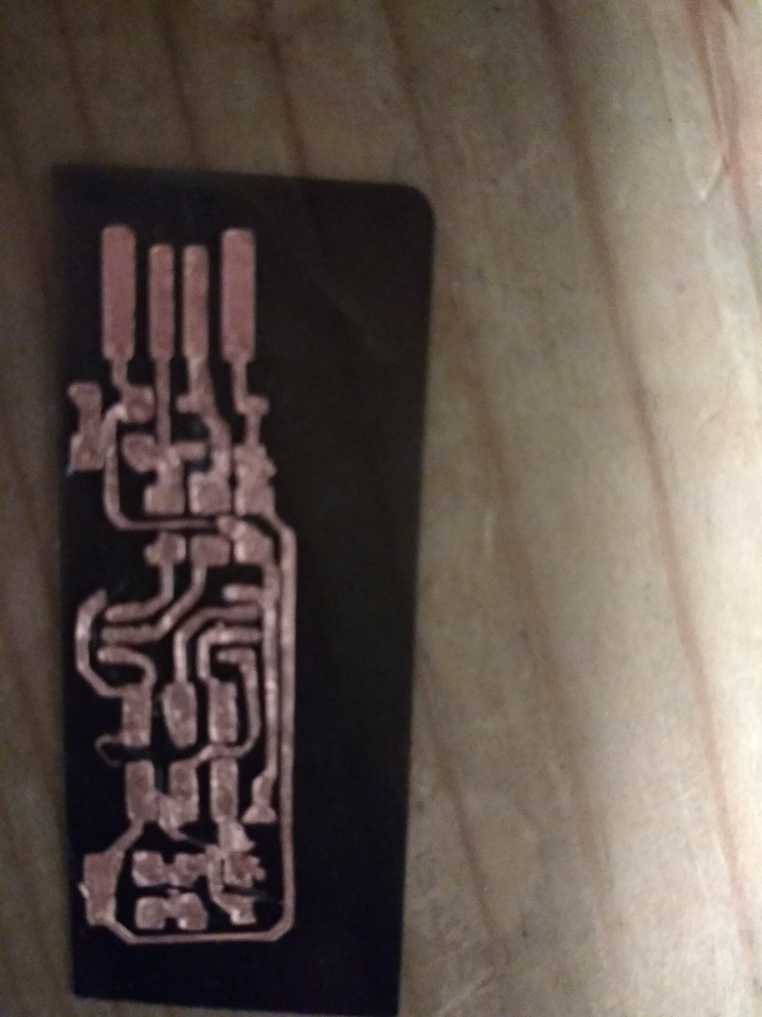
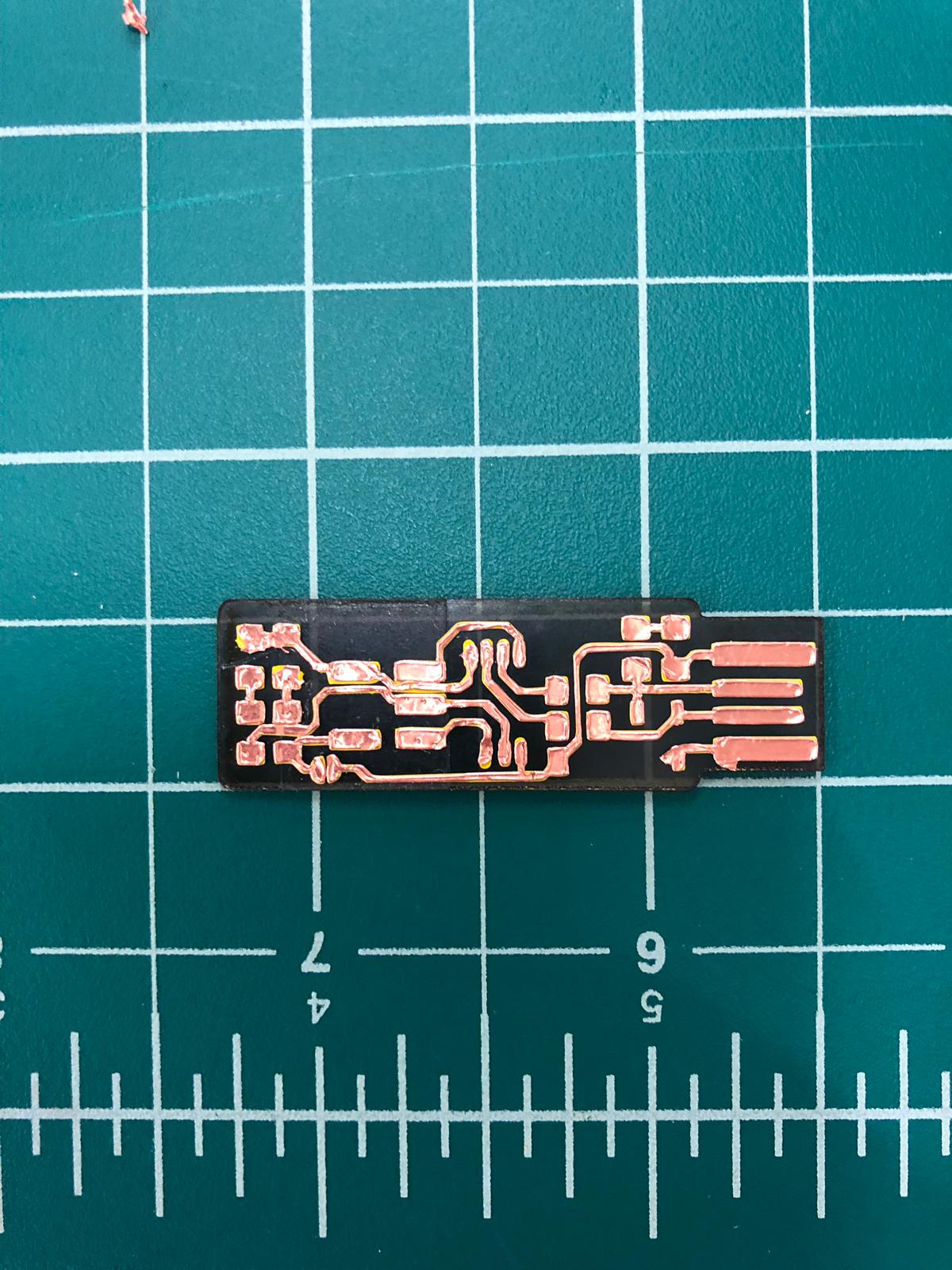
Flexible Circuit Cutting
I also worked the flexible circuit cutting technique.
This was a really hard process, its clearly not as simple as you may imagine. I literally tried to make almost 50 boards.
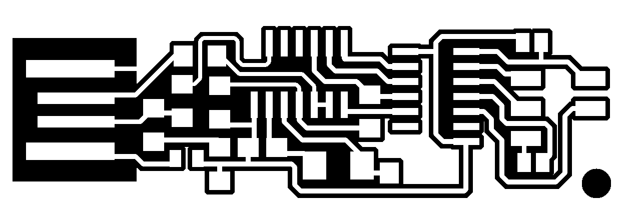
The Files:
Traces:
Interior

Part Detail:
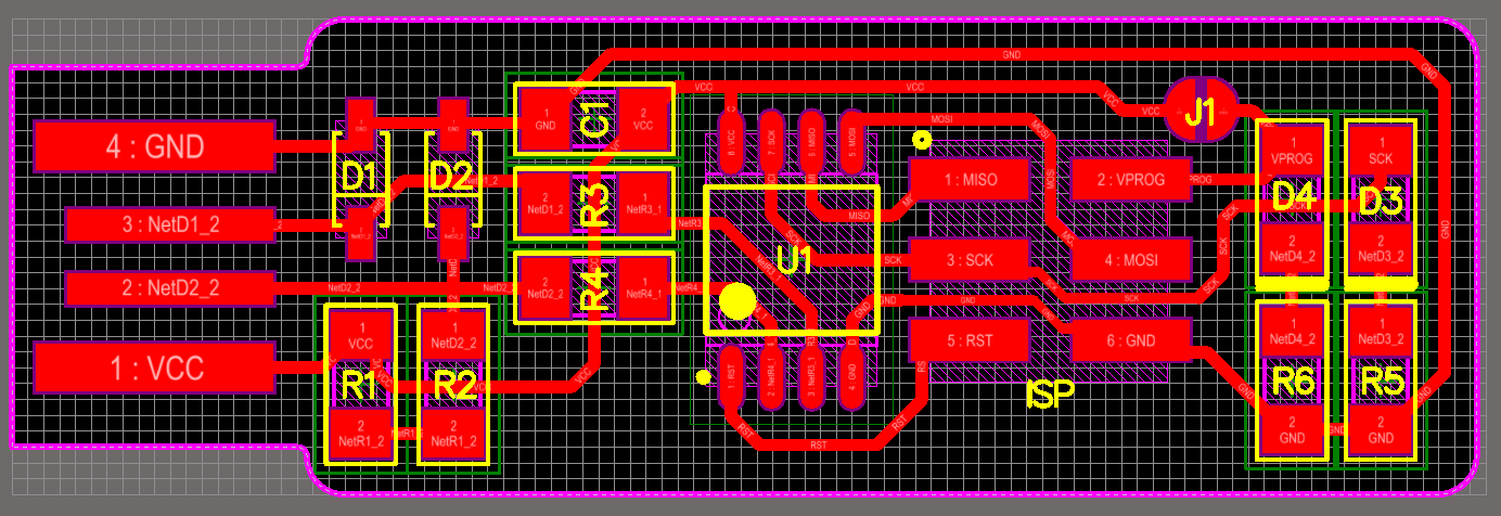
Materials
- 1x ATtiny45 or ATtiny85 [U1]
- 2x 1kΩ resistors [R1 & R6]
- 2x 499Ω resistors [R2 & R5]
- 2x 49Ω resistors [R4 & R3]
- 2x 3.3v zener diodes [D1 & D2]
- 1x red LED [D3]
- 1x green LED [D4]
- 1x 100nF capacitor [C1]
- 1x 2x3 pin header [ISP]
Steps
0.- Laser cut:
Laser cut some acrylic to paste your flexible circuit board:
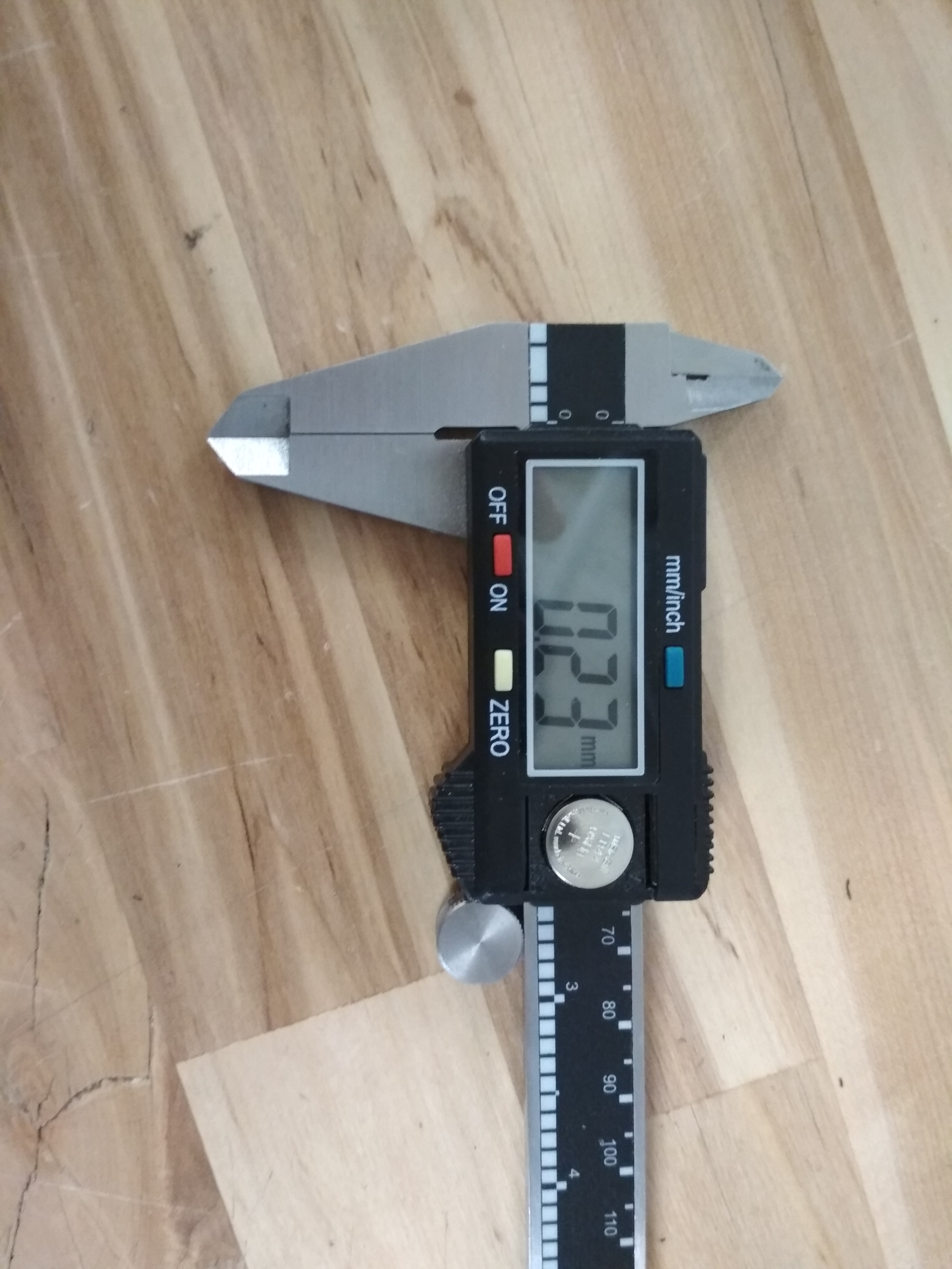
1.- Cut Depth:
This is the key parameter, if you don’t do ok this step, you will finish with something like this:
After a lot of errors, I got to the number 0.23 mm, that is the same that saying “the knife should just be starting to come out of the knife case”:
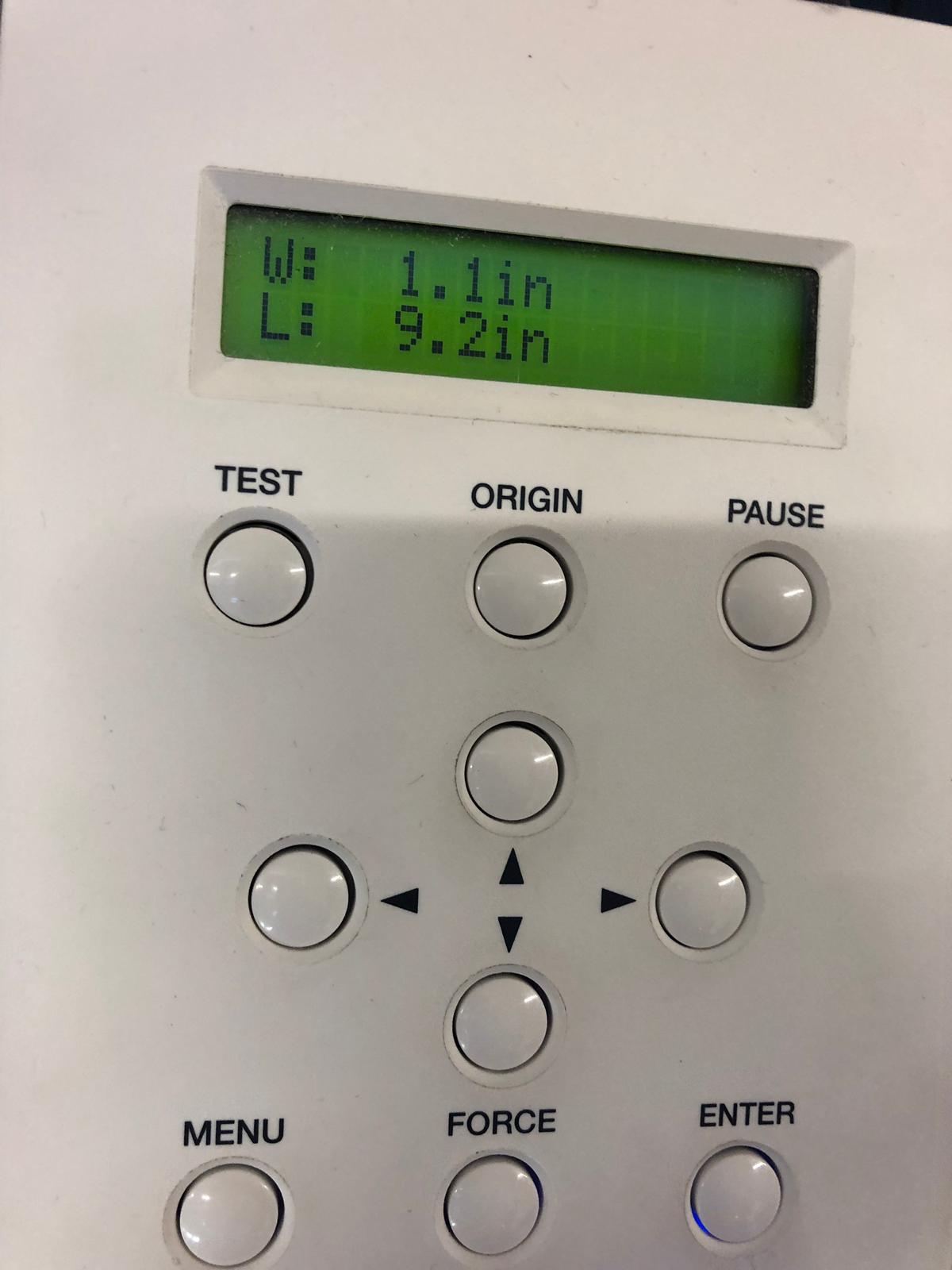
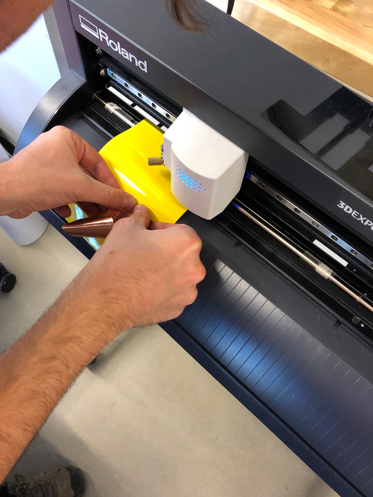
2.- Vinyl cutter parameters:
After testing a lot of different combinations I got to the numbers:
- Force: 60g
- Speed: 2cm/s
At the moment you start the machine, you have to store your “Working 0”
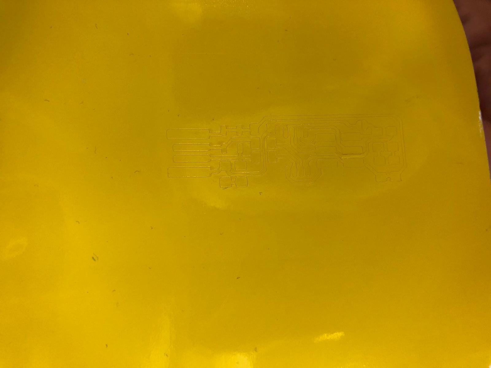
3.- Cut normal Vinyl First
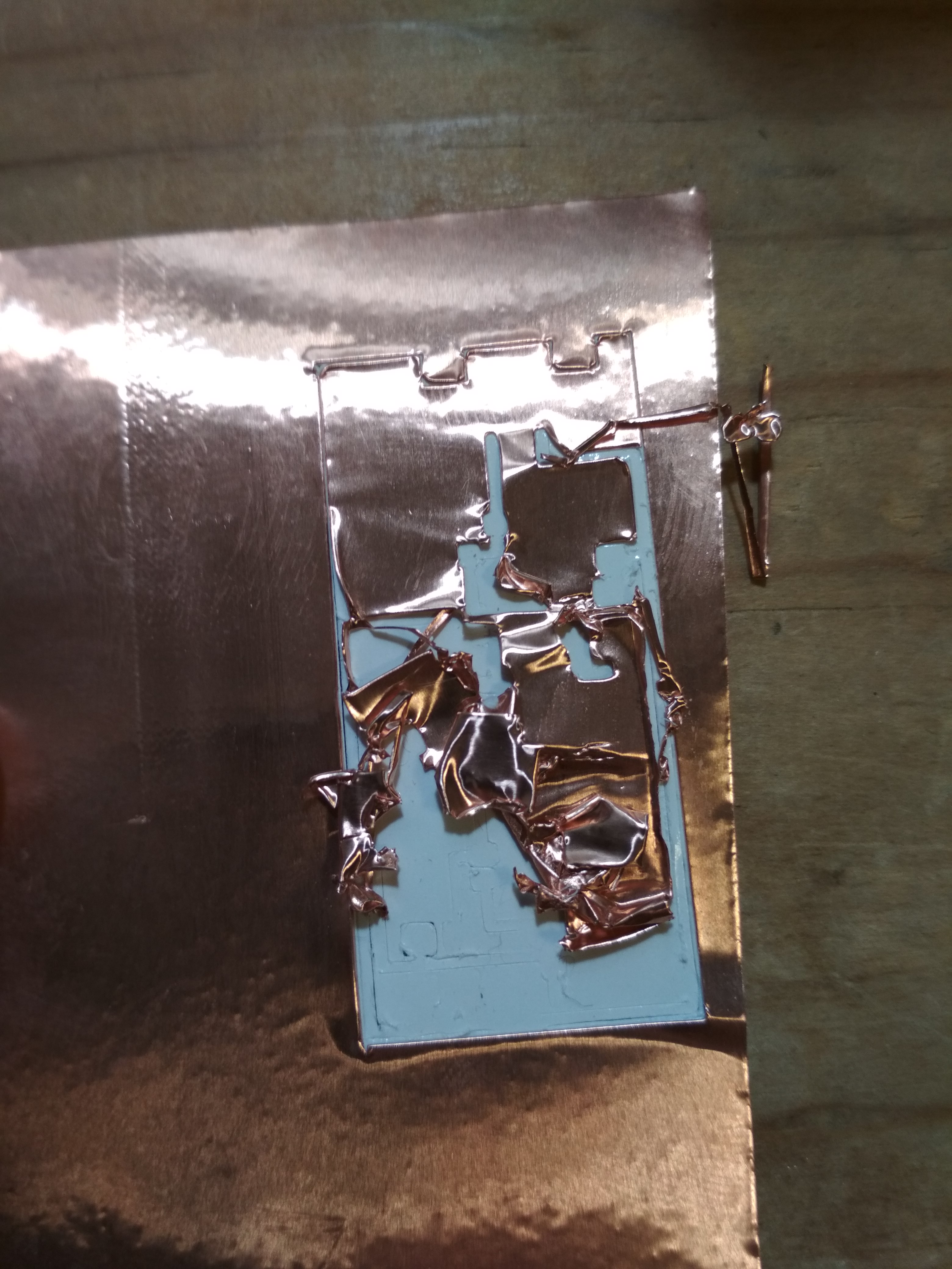
Copper vinyl is really hard to cut, so when I managed to get a cut depth that didn’t destroyed the whole circuit board, normally it wasn’t enough to cut through the copper:
Also, when I thought I has managed to find the perfect combination, I got lots of problems riping of the copper in the areas it shouldn’t go:
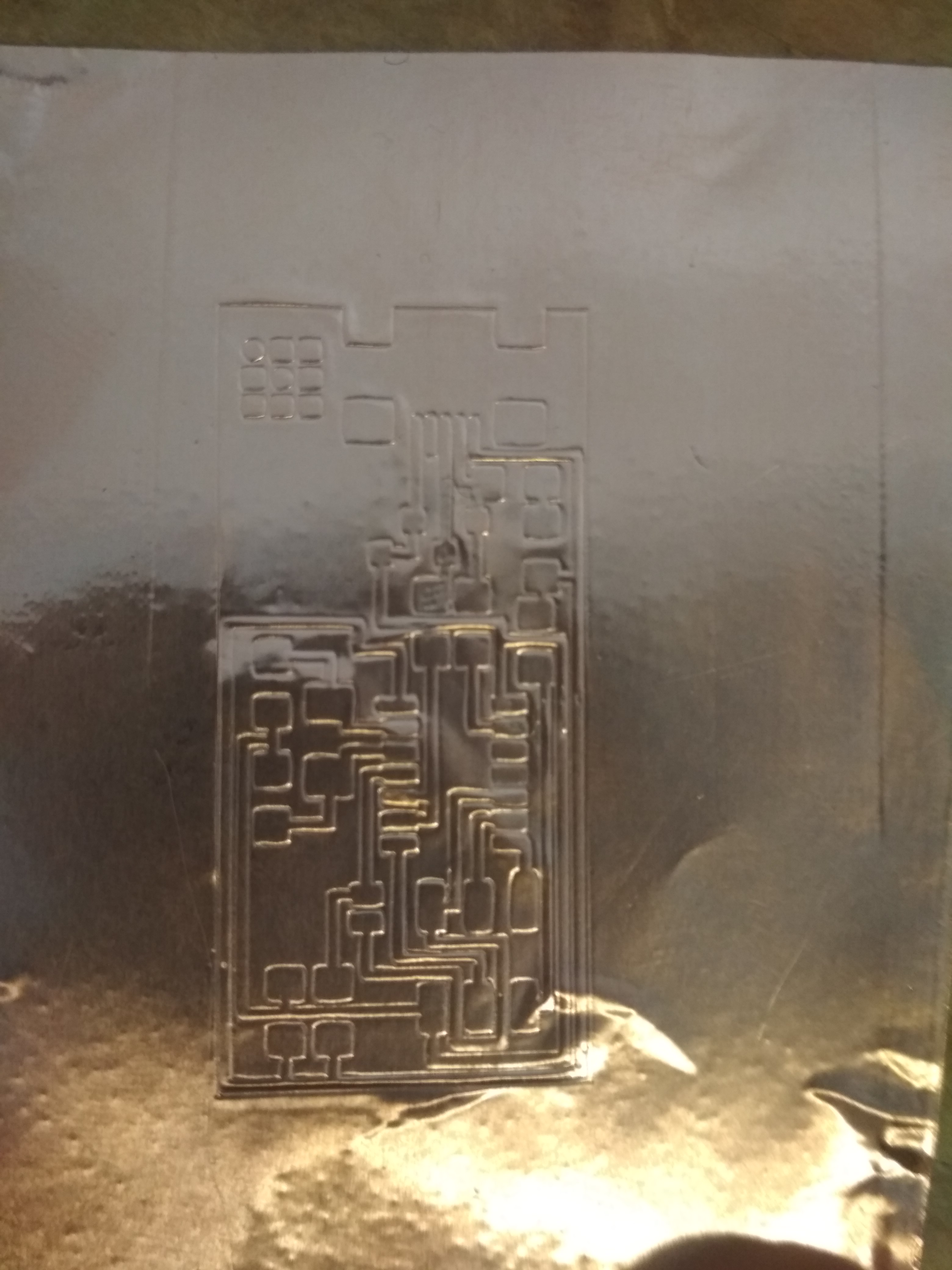
It’s better to have vinyl first, because it is easier to remove, you’ll get something like this:
4.- Paste the copper:
Now you have to move the cutted vinyl, so we can paste above it the copper and then cut everything. It’s really important to store the 0 you are working with, if not you could lose all your work (see step 2).
5.- Cut Borders:
Now you just cut the interiors.
6.- Transfer tape:
You will use transfer tape to get you traces into a flexible structure:
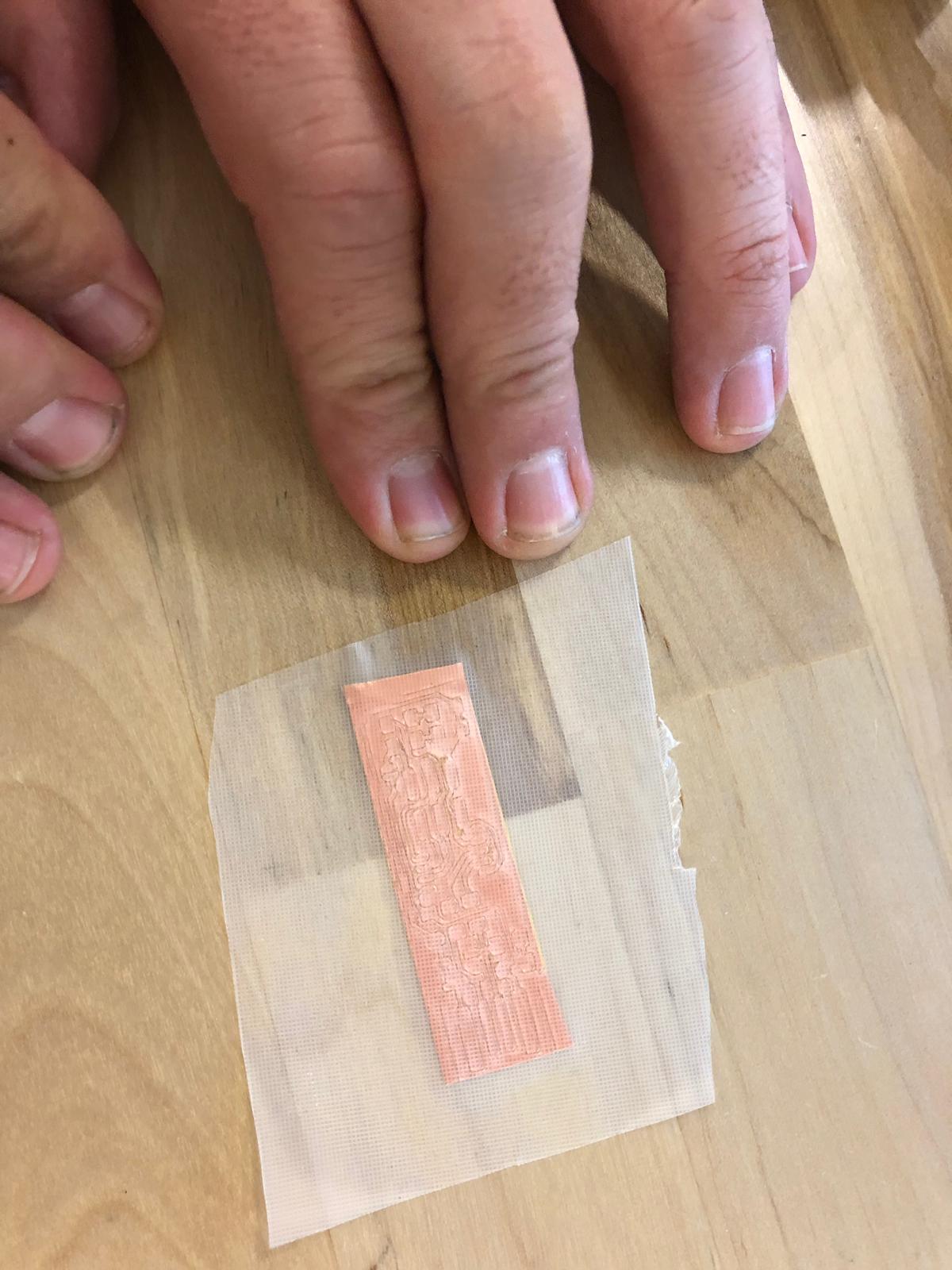
You should get something like this:
And advice, use 2 tweezers, one to get ripped of the extra material, and the other fix the traces so they doesn’t rip off.
7.- Solder:
This is similar to the soldering process for the Milled PCB, but you have to remember that tha plastics melt, be fast!!
Your result should look like this:
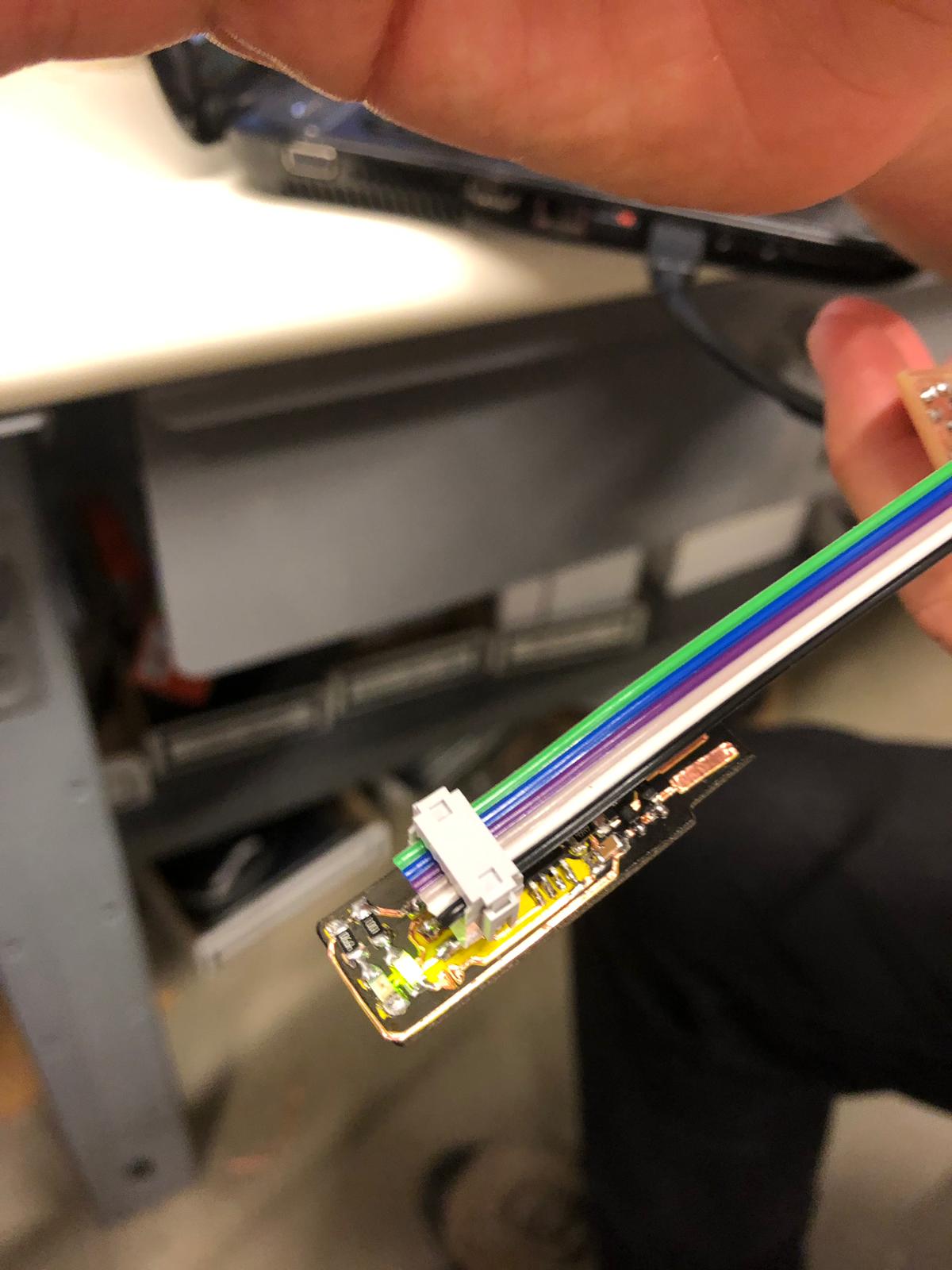
8.- Program!
It’s programed the same way that the milled ISP, but you have an advantage; you have a LED that advices you if your board is working: