3. Computer Aided Design
In this week we had an introduction to graphic software for computer design. The idea was to take a look into the biggest amount of them that we could.
In this week advances I would present some quick results I got modeling in 3 or 2 dimensions, the structure of a Drone. I used different software, and would write my conclusions in most of them.
Gimp
GIMP is a free and open-source raster graphics editor used for image retouching and editing, free-form drawing, converting between different image formats, and more specialized tasks.
My objective using GIMP was to learn how to re-touch images, draw and learn how to use layers.
In order to do this I used a Wacom; Pen computer design, that helped get from real life drawing into a digital concept. A tutorial of how to use a Pen Computer Design device in GIMP is copied in the useful links.
As I’m not a keen drawer, I just followed the structure of the Satshakit flight controller.
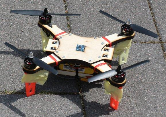
This is the result I got from that process:
As you can see, the result is not as similar as I would like, but I was a good introduction into how to use GIMP.
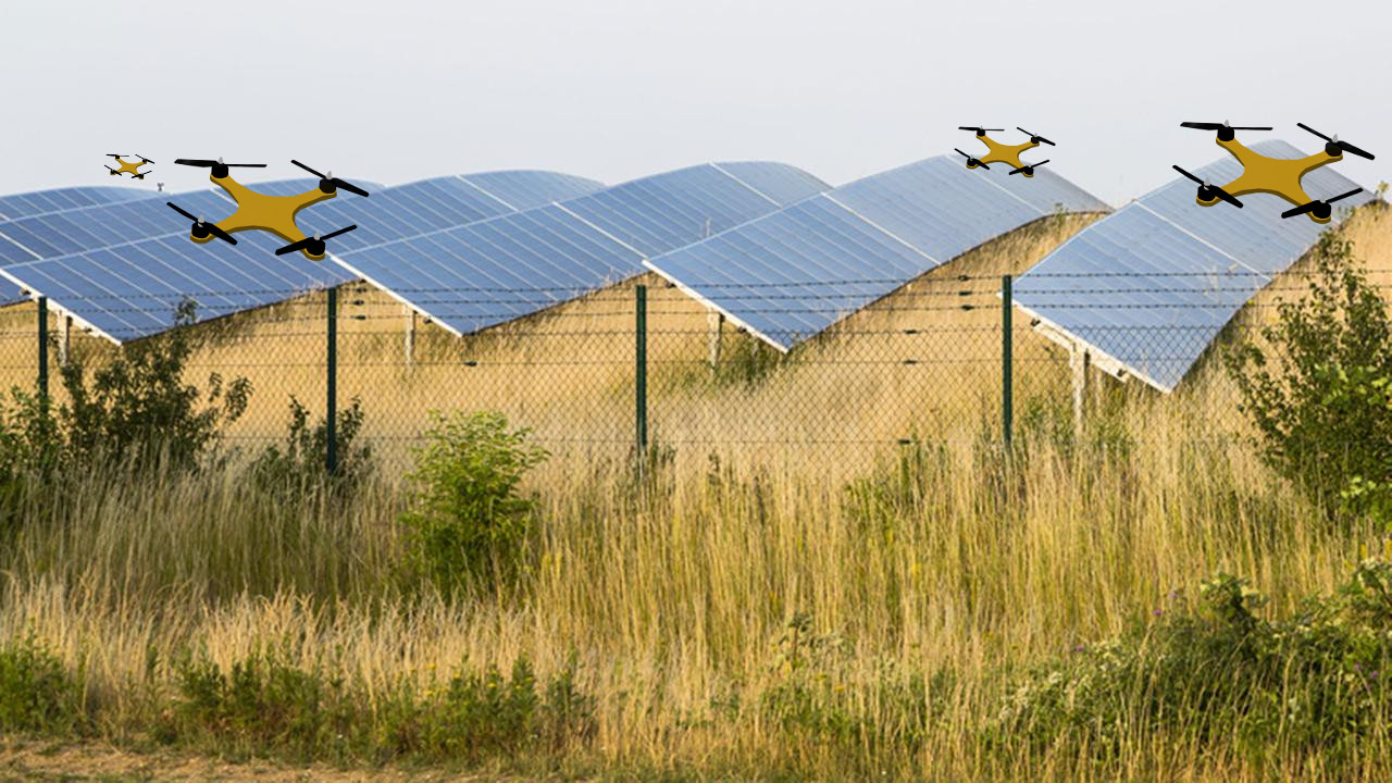
Then I wanted to mix some images, to have a result were I can get a real imagen and insert the drawings to give the idea that there was a Drone fleet monitoring the Solar Field.
Useful links
Inkscape
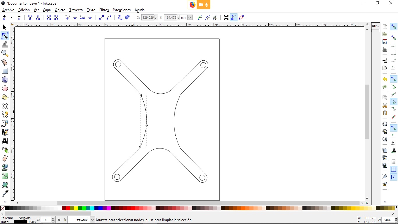
Inkscape is a great tool to develope vector, specialy to use it with a laser cutter. I used a video tutorial to learn all about this software.
I posted a really complete one in the usefull links.
I didn’t Inkscape as a design tool as it self, I prefered to get something that allready exists and vectorice it. This could be a Bitmap, an image or a sketch you get from a 3D modelling software as Fusion 360.
All this process is explained in the videos I posted, so I just would present the results I got from opening the sketch I developed in Fusion 360 into Inkscape.
Useful Links
Blender
Blender is a free and open-source 3D computer graphics software toolset used for creating animated films, visual effects, art, 3D printed models, interactive 3D applications and video games. Blender’s features include 3D modeling, UV unwrapping, texturing, raster graphics editing, rigging and skinning, fluid and smoke simulation, particle simulation, soft body simulation, sculpting, animating, match moving, rendering, motion graphics, video editing and compositing.
My objective when I started using Blender was to develop a similar image to the one that I had made through GIMP, but of course, with a better quality.
I have posted the 2 tutorials that taught me how to use this platform. Which I highly recommend, they teach you all the tools the you can use, and the differences between Blender and other 3D modeling software, its advantages, and its capacities; unfortunately for non spanish speakers, this videos are in spanish.
This were the results I’ve got from the 3D design of a Drone.
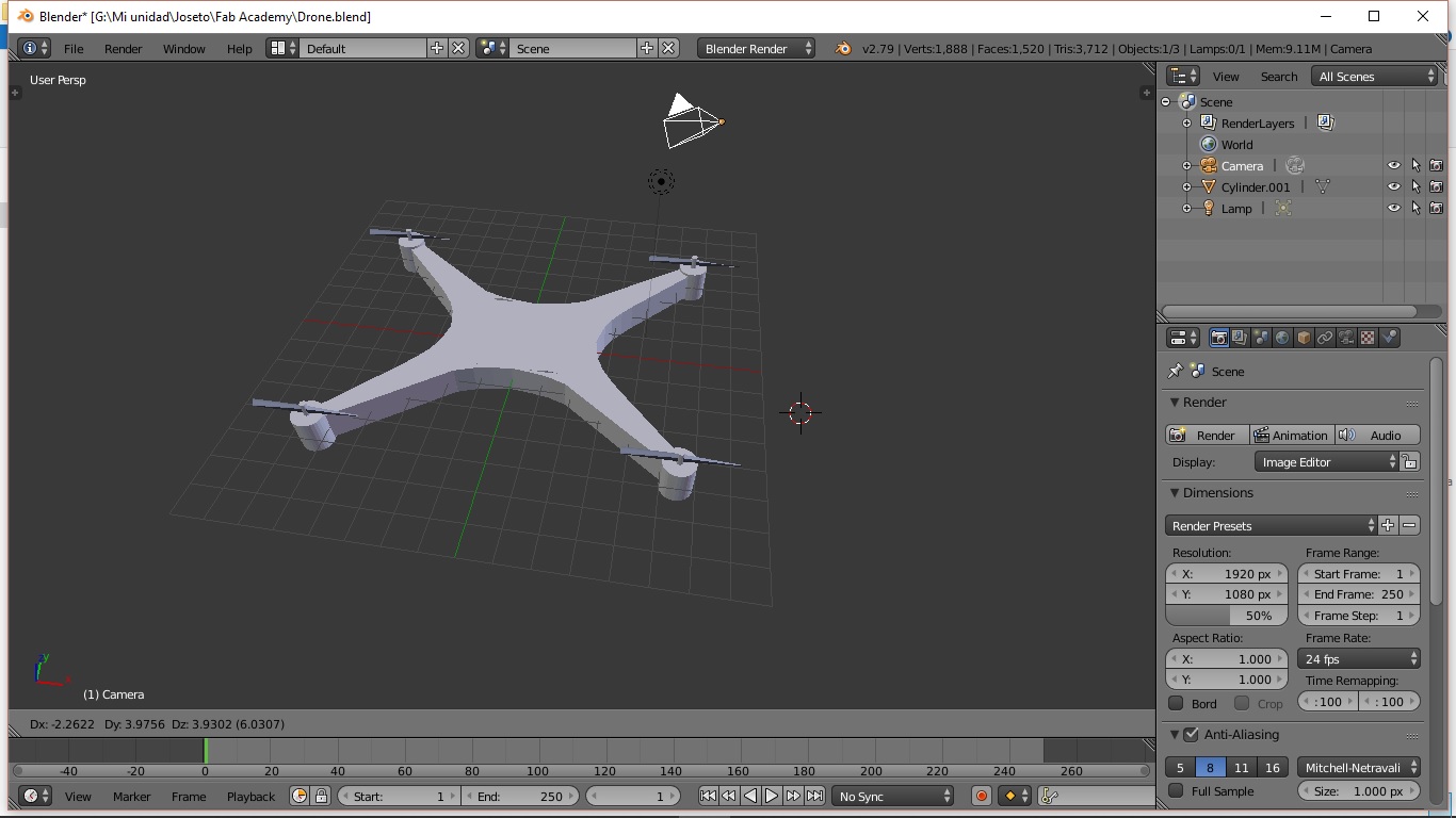
Unfortunately I didn’t liked Blender, because it’s too far away from parametric 3D Design Software. So I stopped my work there, since my Fab Academy instructors told my there were other software’s were I could developed renders and videos with similar qualities than Blender, and that fitted more my personal qualities and views.
Useful links
Fusion 360
Fusion 360 was an easier to learn, because I had worked with Autodesk Inventor; that is a parametric 3D design software developed by Autodesk, same company that develops Fusion 360, so they are extremely similar.
My objective was to continue with the same Drone structure I’ve been developing in the different software’s, but this time, make 3 different parts and assemble.
While the motor and the drone’s base structure were simple; the drone’s helix was much more complex, because it had to have a rotation around its extrusion. I solved this problem through a video tutorial that you can see in the useful links.
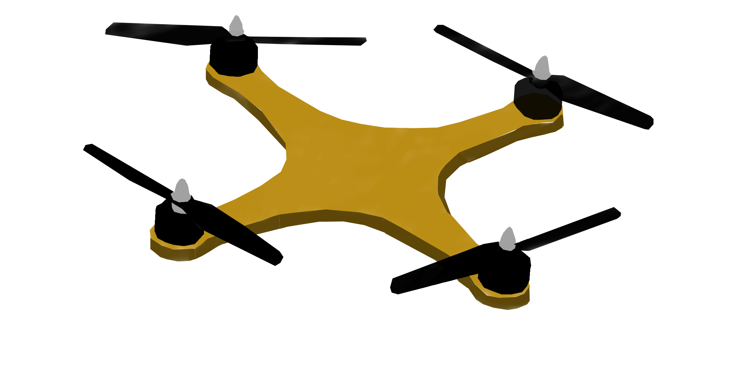
Finally I wanted to present a render of the assemble, which should be the standard way to present results from now on, to learn how to make a render in Fusion 360, I used a video tutorial that’s in the useful links.
Now I’m going to present the results:
Drone Base:
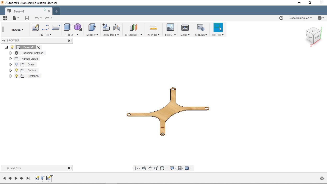
The main function I used to construct the plane I extruded to developed the base structure was the mirror function, as you can see, it is completely symmetric, so I just built 1/4 of the hole structure.
Motor:
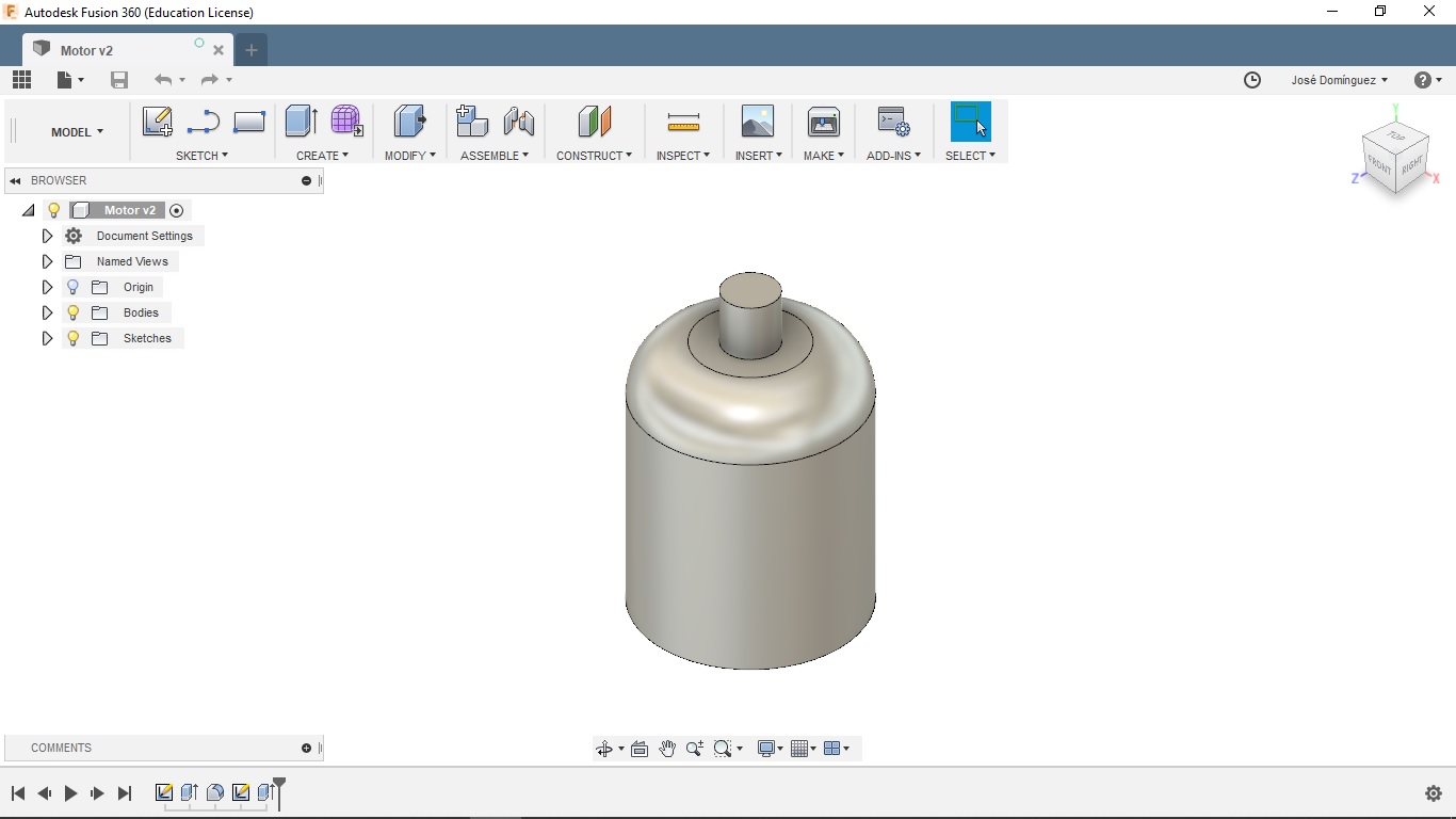
This consist in 2 extrusions and a filet.
Helix:
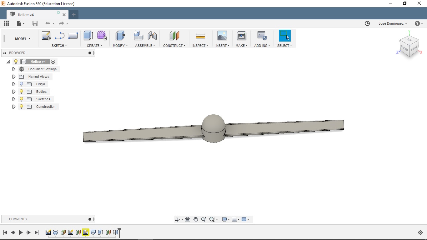
The explanation of how to build a helix in Fusion 360 can be seen in the useful links.
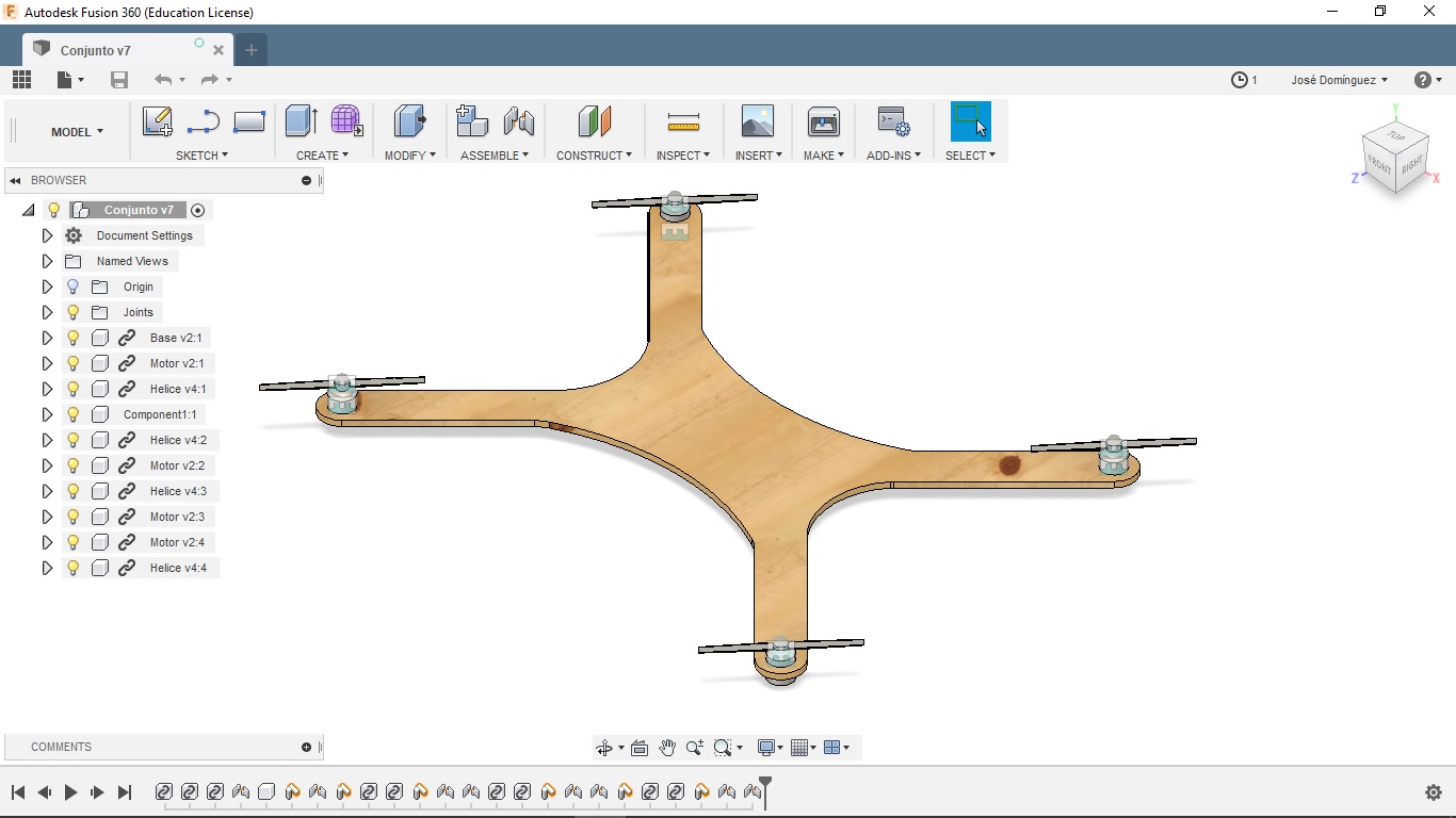
Assembly:
The assembly gives the user the possibility to join all the parts that are going to work in the system, through a series of physical constrains that would allow us to understand how the system would look, and work in the real world. This constrains can be static or dynamic.
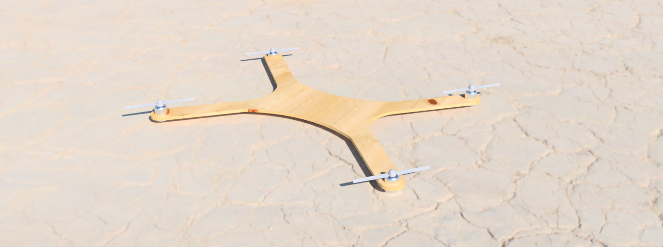
Render:
I had never developed a render using Fusion 360 or Inventor, so it was a completely new task. I found a really good short video in tutorial that would help anyone that’s trying to make a good render using this software.
This is what I got:
Useful Links
Rhino
Unlike the other software’s, I learned Rhino through the classes teached by Luciano Betoldi, instructor at Fab Academy in Dassault Systems.
Rhino is a 3D modelling software that offers the possibility to work free hand, or parametric, with its add-on Grasshopper. We will start analyzing Rhino, the constructive solid geometry main software.
At first it really got my attention that you could see the four views simultaneously, this is something that I have never seen before, and didn’t saw in the software’s already shown.
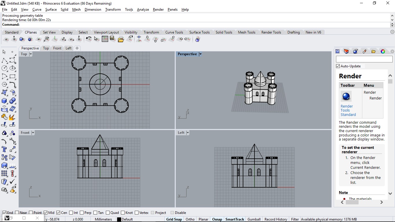
This allows you to work in an specific plane, and check out in which planes are you working in other dimensions, making easier for the user the three dimensional view extrapolation of the work.
It also has the possibility to work in a click and play format, selecting manually each command you want to use, until you are a keen Rhino user and you can type the commands.
Each command has its configuration, and it is shown in the command terminal:
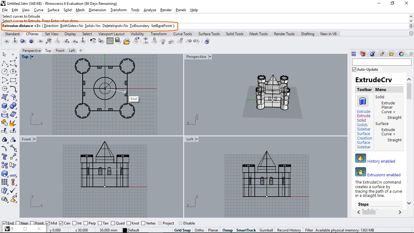
Here is a list of the commands I have used until this moment: - ExtrudeCrv: Creates a surface by tracing the path of a curve in a straight line. It is really important to select S in case you want to extrude a solid and not a surface. - Array: Copies objects spaced in columns, rows, and levels in the x, y, and z directions. This allow us to make patterns faster and easier. - ArrayPolar: Same that array but instead of using Cartesian coordinates, you use polar coordinates. - Explode: Divides a group of elements, into their minimum part. - Join: A group different parts into one structure. - Trim: Cuts and deletes selected portions of an object at the intersection with another object. - Booleand Operations: Allows the user to add, subtract or work only with the union of 3D components. - Sweep: Transfer an chosen area through a path line, developing a surface or solid.
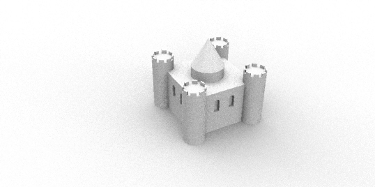
Finally, many for the render options they exist on Fusion 360 or Blender also exists in Rhino, here is the render I developed:
Grasshopper
Grasshopper is a visual programming language and environment that runs within the Rhinoceros 3D computer-aided design (CAD) application. Programs are created by dragging components onto a canvas. The outputs to these components are then connected to the inputs of subsequent components.
I started using Grasshopper because it gives parametric structure to Rhinoceros. It’s been one of the hardest, but more useful software I tested this week. There’s a lot to read and understand before modeling; in the useful links, there’s a basic tutorial were basic principles of Grasshopper are explained.
Basic Concepts:
Parameter: Factor that helps to define the overall limits and performance of a system. In Grasshopper you work through parameters, and not the shape of the model.
Objects:
In the following figure you can see a standard Grasshopper object and its main parts.
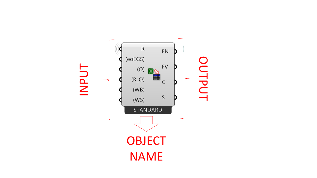
There are two main type of objects: - Container: Entities that contain data => Store things - Constructor: Component that facilitates task => Do things
The following figure shows the result of making a construction into an existing object:
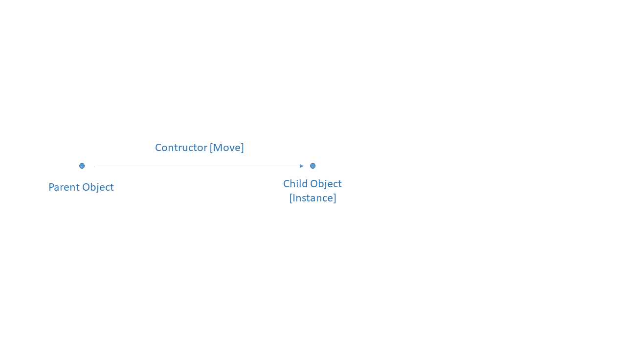
So, the parent object doesn’t change, it just generate another object as an instance. A parent object can have multiple instances.
Referring: Get something from Rhino to Grasshopper. Its easier to work everything in Grasshopper to avoid problems, so refereeing is not recommended.
Problems:
I had a lot of problems working with curves:
-
Trim: Trimming 2D curves isn’t as simple as it is in Fusion 360 or Rhinoceros, that’s why I finally preferred working with points and build the curves afterwards.
-
Join: Had a lot of problems joining curves between each other, because when I used the join object, and inserted more than one curve, the previous one was unselected. This is solved by clicking shift at the moment of joining curves.
-
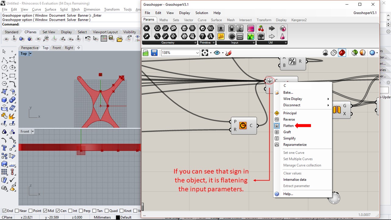
Flatten or Graft: Sometimes you like to move data from one data structure to another one, but the define layout we’ve got doesn’t fit the desired operation.
Its really simple to flatten the input parameters, just right click tke objects wich inputs are having problems:
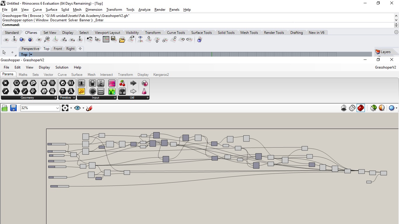
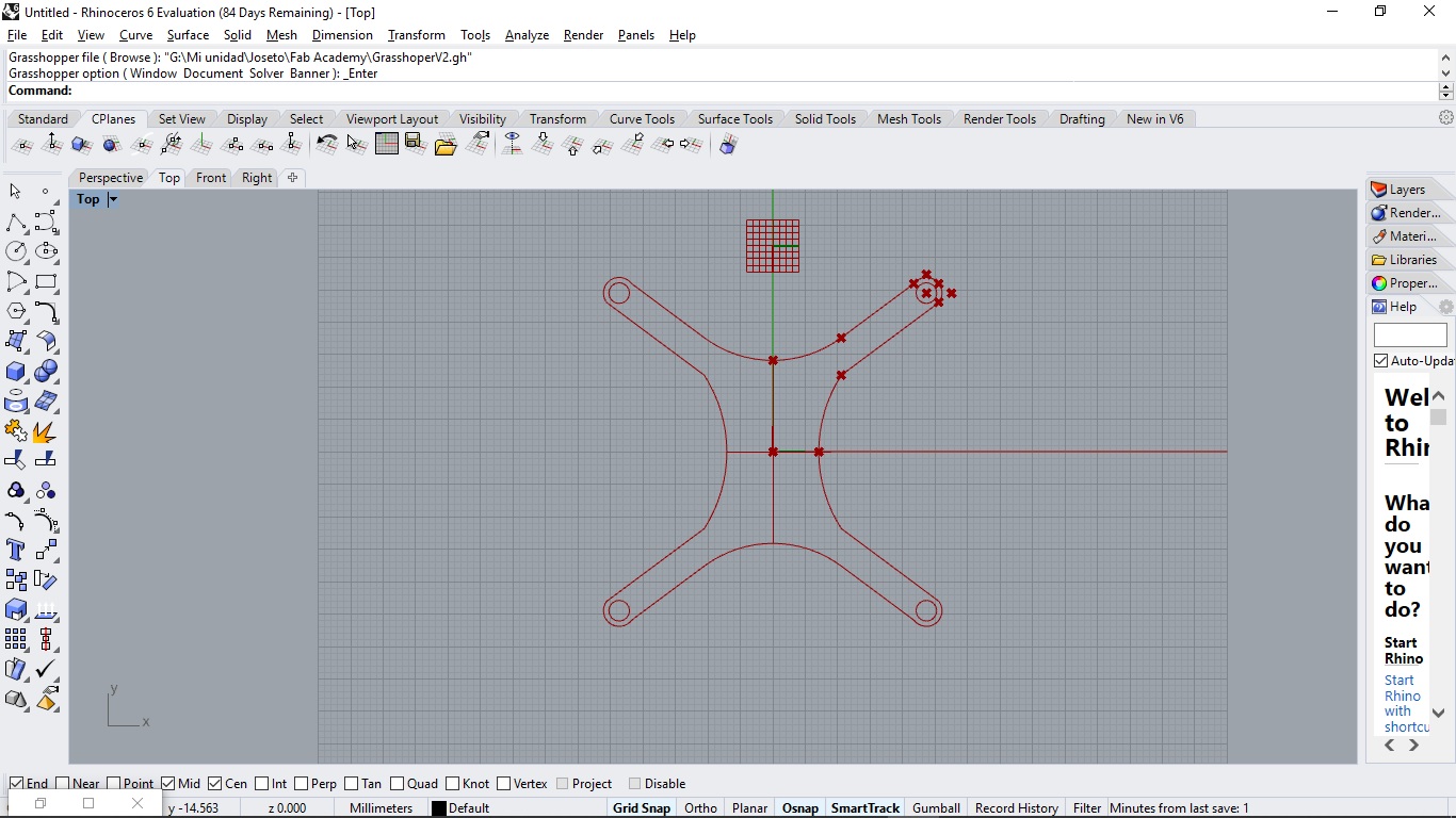
Results:
Here is the same model base thatI have made in Fusion 360, Blender and Gimp, with the advantaje that, thanks to Grasshoper I can change key parameters without the necesity of biulding everything again.
And in the following figure you can see the Grasshoper block diagram: