9. Embedded programming
All this information is refered to Embedded Programming class.
Assigment
- Read a microcontroller data sheet.
- Program your board to do something with as many different programming languages and programming environments as possible.
Group Assigment
Compare the performance and development workflows for other architectures.
DataSheet
Pin Map
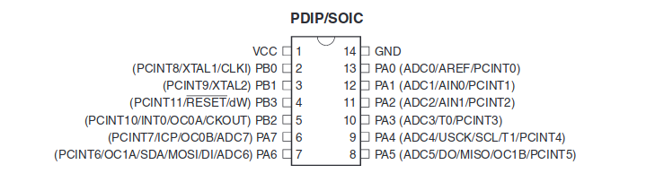
Atmel divides there pins in bit groups defined by letters, in this case PB and PA, plus a VCC and a GND.
Port B:
A 4-bit bi-directional I/O group with an internall pull-up resistor. PB3 acts as a RESET pin.
Port A:
A 8-bit bidirectional I/O group with an internall pull-up resistor. This pins are atached to a ADC so they can read analog inputs, make analog comparations, act as timer/counter, SPI and pi change interrupt.
Architecture
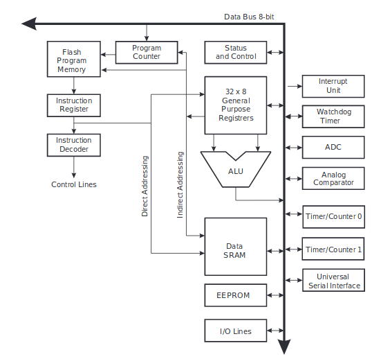
To optimize perform AVR uses a Harvard Architecture, with separate memories and buses for program and data. It also runs every intructions in every clockcycle, due to the single level pipeline, meanwhyle one isntruction is being executed, the other one is being pre-fetched to the program memory; this is the combinated work of the Program Counter, Flash Program Memory, Instruction Register ans Instruction Decoder all at the left part of the diagram.
Arithmetic Logic Unit (ALU)
As you can see in the diagram, the ALU operates in direct conection with the 32x8 general purpose working register (wich I will describe later), wich allows to execute arithmetic operations in a single clock cycle. This operations are devided into 3 categories; arithemtic, logical and bit-functions.
Memories
| Memory Type | Space |
| Flash | 4K |
| SRAM Data Memory | 256 |
| EEPROM | 256 |
All units are in bytes.
Flash Memory
Flash memory is an EEPROM type of memory comunly used for program storage, due to the posibility to read/write this memories through blocks. It has an endurance of 10.000 write/erase cycles for the attiny 44. It has 2048 16-bits locations.
SRAM Data Memory
The SRAM Data Memory is divided into 3 main grups:
- Register File: 32 adress
- I/O Memory: 64 adress
- Internal Data SRAM: 256 adress
The following list shows all adress directions:

EEPROM
As you can see in figure 1, it is organized as a separate data space. EEPROM is a non-volatil small memory, comonly used to store long term variables. It has an endurance of 100.000 write/erase cycles.
The access between the EEPROM and the CPU is described in the following; specifying, address register, data register, and the control register.
To see how to access each parameter go to the following link in the datasheet Link.
I/O Ports
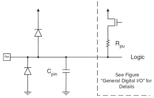
The following figure is a schematic representation of the equivalent schematic of the pin inside the microcontroller. We can see the as the pull-up resistor, that has to be enabled with the gate thats upwards, so you can use it just in case it act as an INPUT pin.
2 diodes, one going to and the other one to GND for voltage stability.
At last we have the actign as filter.
Each port is alocated with 3 diferent memory address location:
- Data Direction Register (DDRx): An 8-bit register where the user can define if the pins are going to act as INPUT (0) or OUTPUT (1).
- Pin Register (PINx): An 8-bit register that stores the current state of the physical pins.
- Port Register (PORTx): - Enables/disable the pull-up resistor in input pins.
- Set to HIGH/LOW the output pins.
Future Questions
During this week, reading the datasheet I learned the basis of how the AVR family of microcontrollers work. How the memories are distributed, how to call registers, asign pins, etc. All of this can be seen in the C code presented in the next part.
I’m lookng forward for the future weeks, to learn how to use the ADC registers, and hardware built in PWM.
Workflows
Arduino IDE

To get from your Arduino IDE code to into the Arduino Board, or in this case, the Attiny 44 there are a series of “unseen” steps.
1.- The code is turn from processing lenguage to C++.
2.- It goes through the Avr-Gcc compiler wich turns the human readable code into machine readable instructions (object file).
3.- The code is linked against the standard Arduino Libraries, resulting on a single Intel hex file.
4.- The code is uploaded using the avrdude uploading tool.
Command Line
You can also follow this same steps through the command line in a Linux machine. This only works if youre code is done complitly in C, without using the Arduino enviorment.
The first step is to develope a Makefile:
PROJECT=Serial_V2 #Project name
SOURCES=$(PROJECT).c
MMCU=attiny44
F_CPU = 20000000 #Clock of the microcontroller

CFLAGS=-mmcu=$(MMCU) -Wall -Os -DF_CPU=$(F_CPU)

$(PROJECT).hex: $(PROJECT).out
  avr-objcopy -O ihex $(PROJECT).out $(PROJECT).c.hex;\
   avr-size --mcu=$(MMCU) --format=avr $(PROJECT).out

$(PROJECT).out: $(SOURCES)
  avr-gcc $(CFLAGS) -I./ -o $(PROJECT).out $(SOURCES)

program-bsd: $(PROJECT).hex
  avrdude -p t44 -c bsd -U flash:w:$(PROJECT).c.hex
#choose the board you are going to program, in the terminal type Makefile (baord). Example: make program-usbtiny
program-dasa: $(PROJECT).hex
  avrdude -p t44 -P /dev/ttyUSB0 -c dasa -U flash:w:$(PROJECT).c.hex

program-avrisp2: $(PROJECT).hex
  avrdude -p t44 -P usb -c avrisp2 -U flash:w:$(PROJECT).c.hex

program-avrisp2-fuses: $(PROJECT).hex
  avrdude -p t44 -P usb -c avrisp2 -U lfuse:w:0x7E:m

program-usbtiny: $(PROJECT).hex
  avrdude -p t44 -P usb -c usbtiny -U flash:w:$(PROJECT).c.hex

program-usbtiny-fuses: $(PROJECT).hex
  avrdude -p t44 -P usb -c usbtiny -U lfuse:w:0x7E:m

program-dragon: $(PROJECT).hex
  avrdude -p t44 -P usb -c dragon_isp -U flash:w:$(PROJECT).c.hex
Type in the terminal:
make program-usbtiny
And your will recieve something like this:
avr-gcc -mmcu=attiny44 -Wall -Os -DF_CPU=20000000 -I./ -o Serial_V2.out Serial_V2.c
avr-objcopy -O ihex Serial_V2.out Serial_V2.c.hex;\
   avr-size --mcu=attiny44 --format=avr Serial_V2.out
AVR Memory Usage
----------------
Device: attiny44

Program:     758 bytes (18.5% Full)
(.text + .data + .bootloader)

Data:         64 bytes (25.0% Full)
(.data + .bss + .noinit)


avrdude -p t44 -P usb -c usbtiny -U flash:w:Serial_V2.c.hex

avrdude: AVR device initialized and ready to accept instructions

Reading | ################################################## | 100% 0.00s

avrdude: Device signature = 0x1e9207 (probably t44)
avrdude: NOTE: "flash" memory has been specified, an erase cycle will be performed
         To disable this feature, specify the -D option.
avrdude: erasing chip
avrdude: reading input file "Serial_V2.c.hex"
avrdude: input file Serial_V2.c.hex auto detected as Intel Hex
avrdude: writing flash (758 bytes):

Writing | ################################################## | 100% 1.15s

avrdude: 758 bytes of flash written
avrdude: verifying flash memory against Serial_V2.c.hex:
avrdude: load data flash data from input file Serial_V2.c.hex:
avrdude: input file Serial_V2.c.hex auto detected as Intel Hex
avrdude: input file Serial_V2.c.hex contains 758 bytes
avrdude: reading on-chip flash data:

Reading | ################################################## | 100% 1.34s

avrdude: verifying ...
avrdude: 758 bytes of flash verified

avrdude: safemode: Fuses OK (E:FF, H:DF, L:FE)

avrdude done.  Thank you.
C v/s Arduino IDE
Now I’m going to present a code that makes a LED blink through C and one programd using the arduino libraries:
Arduino IDE
int Led1=2;
int Led2=7;
int Led3=8;
int Button=3;

void setup() {
  pinMode(Led1, OUTPUT);
  pinMode(Led2, OUTPUT);
  pinMode(Led3, OUTPUT);
  pinMode(Button, INPUT);

}


void loop() {
  if (digitalRead(Button)==0){
  digitalWrite(Led3, HIGH);
  delay(500);
  digitalWrite(Led3, LOW);
  delay(500);
  }
  else{
  digitalWrite(Led2, HIGH);
  delay(500);
  digitalWrite(Led2, LOW);
  delay(500);
  }
}
C code:
#include <avr/io.h>
#include <avr/delay.h>
#include <util/delay.h>
int main (void)
{
DDRA = DDRA | 0b11110111;
DDRB = 0xFF;
while(1) {
if (!(PINA & (1<<PA3))) {
  PORTB |=(1<<PB2); //PORTx |=(the value<<number positions)
  _delay_ms (100);
  PORTB &= ~(1<<PB2);
  _delay_ms (100);
}
  else {
    PORTA |= (1 << PA2);
  _delay_ms (10);
  PORTA &= ~(1<<PA2);
  _delay_ms (10);
  }
};
}
So… why using C instead of the Arduino IDE version, when it is clearly easier?
The answer is are two main reasons:
1.- C is a low level lenguaje that allows the user to program deeply in the memory usage of the device, having a bigger control in what you are developing.
2.- The C developed programs use less memory space that the ones developed in the arduino enviorment, as you will see in the following table where I show the data usage for the codes to make an LED blink:
| Arduino | Pure C | |
| Flash | 1096 | 138 |
| EEPROM | 17 | 0 |
The Video