Week 5 - Electronics Production
Assignment
group assignment:
- characterize the design rules for your PCB production process
individual assignment:
- make an in-circuit programmer by milling the PCB,
- check if you can program it,
- then optionally try other PCB processes
- ATtiny45
- ATtiny44
- USB timing
Last year I did this project but appear to have nuked all of the documentation for it when purging my harddrives at the begining of this cycle.
Therefore I'll have to do it again, that is alright as I ran into some roadblocks getting the programmer to work after making it. There should be ample learning room here still.
Fortunately last years class created fairly detailed instructions on how to use the various machines in the lab.

This is the documentation within my sites file structure - they are individually linked below. The preliminary plan for this year is to recreate these with our updated observations.
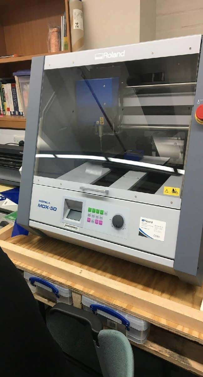
- CNC Cutter - Roland Modela (MDX-50)
- Laser Cutter - Epilog Laser (Helix)
- Vinyl Cutter - Roland (CAMM-1 GS-24)
PCP Production Process
I became interested in cicuit boards when I was back in secondary school, but because of my perception of their complexity I steered clear of getting into electronics unitl recently.
Last year Strange Parts produced a video touring the PCB production process in a factory in China, which is very informative and goes through the full process in a nice, linear, and clear manner:
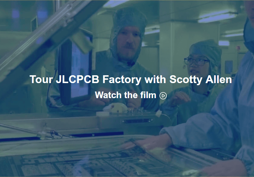
" Printed circuit boards, or PCBs may look really complicated, but they're actually pretty simple. They're a bunch of tiny copper wires, sandwiched in between multiple layers of fiberglass. Now the wires are there to connect all of the various integrated circuits and other electronic components in an organized, repeatable way to make up an electronic circuit. "
There seem to be many different production processes for producing printed circuit boards. These depend on the scalability of the design - or repeatability; and number of layers within the board.
The Labs Equipment
- Machines
- Roland Modela MDX-50
Processes
- The fablab last year created an instruction manual on how to produce the "TinyFABISP" (this is currently within the CNC cutter instructions above)
- There are also other tutorials such as Brian's from the lecture notes.
Machine Test
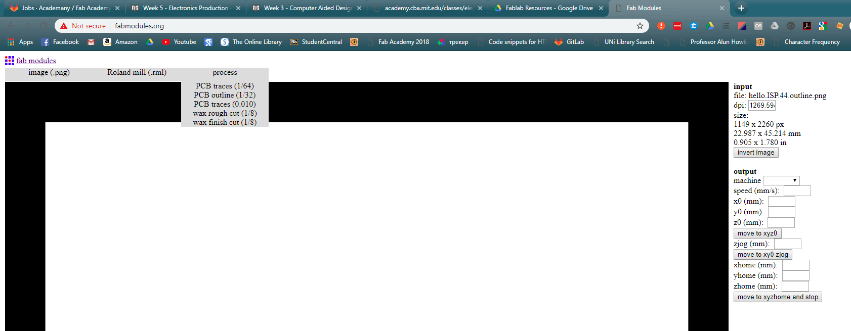
Circuit design - creating RML files
RML files are CAD Files primarily associated with Redline Markup Language File. They are machine readable files that instruct the machine as to the toolpath.
For this assignment it will be required to create two .RML files; one for the traces, and one for the outline.
I will be doing this using fabmodules
Illustrator note: export as -> on quality -> select other -> manual -> 1000 dpi
Setting up MDX-50 Machine
- Fix board
- Setup machine
- To select the tool
- Zero X and Y
- Set Z origin
- Testing depth of cut
- Safer to leave spindle running on Z up in case of user error
- Instructions for changing the tool in the machine
(FabModules) Prep file for traces milling
Set up machine to cut out board outline
(FabModules) Prep file for cutting outline
Cleaning up the board
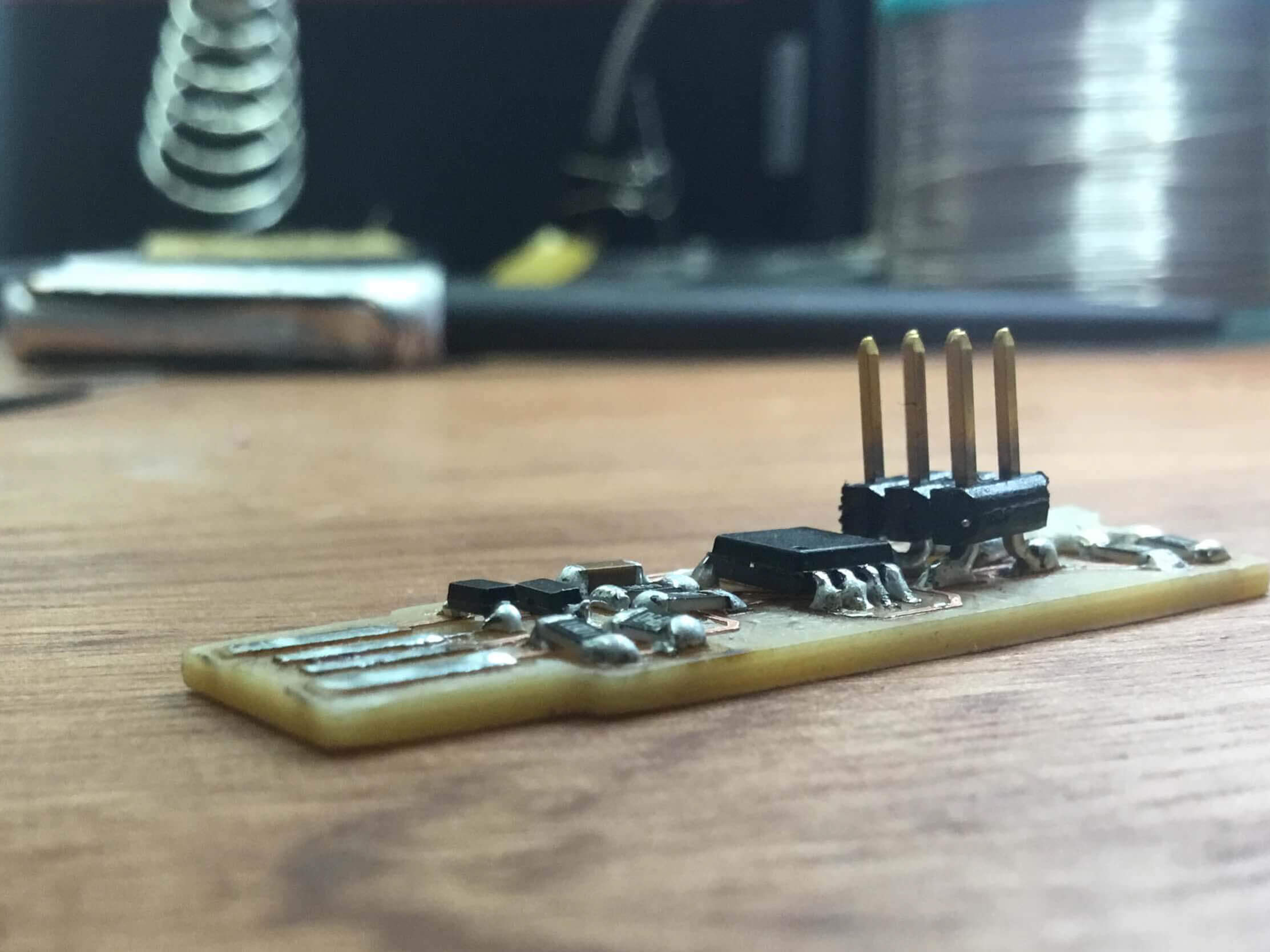
Programmer
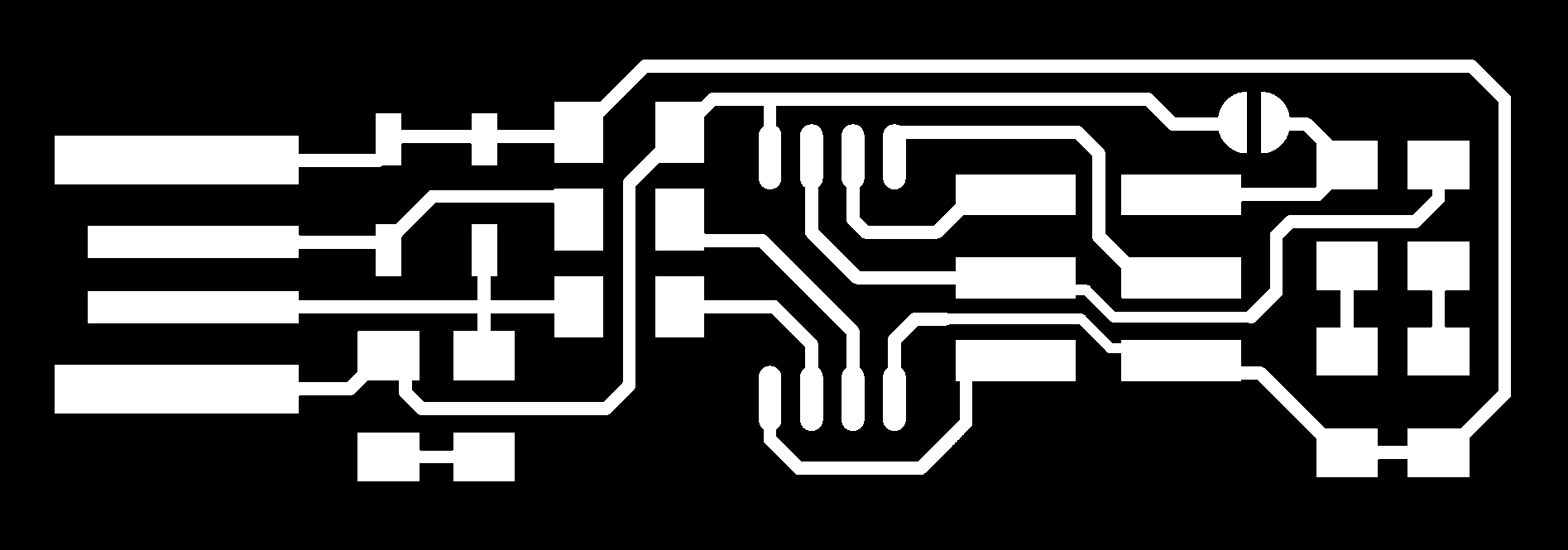
FabTinyStar Traces:
FabTinyStar Interior:

Finished Programmer: