Week 7 - Electronics Design - Part 2 - Time to do things Properly
Redraw the Echo hello-world Board
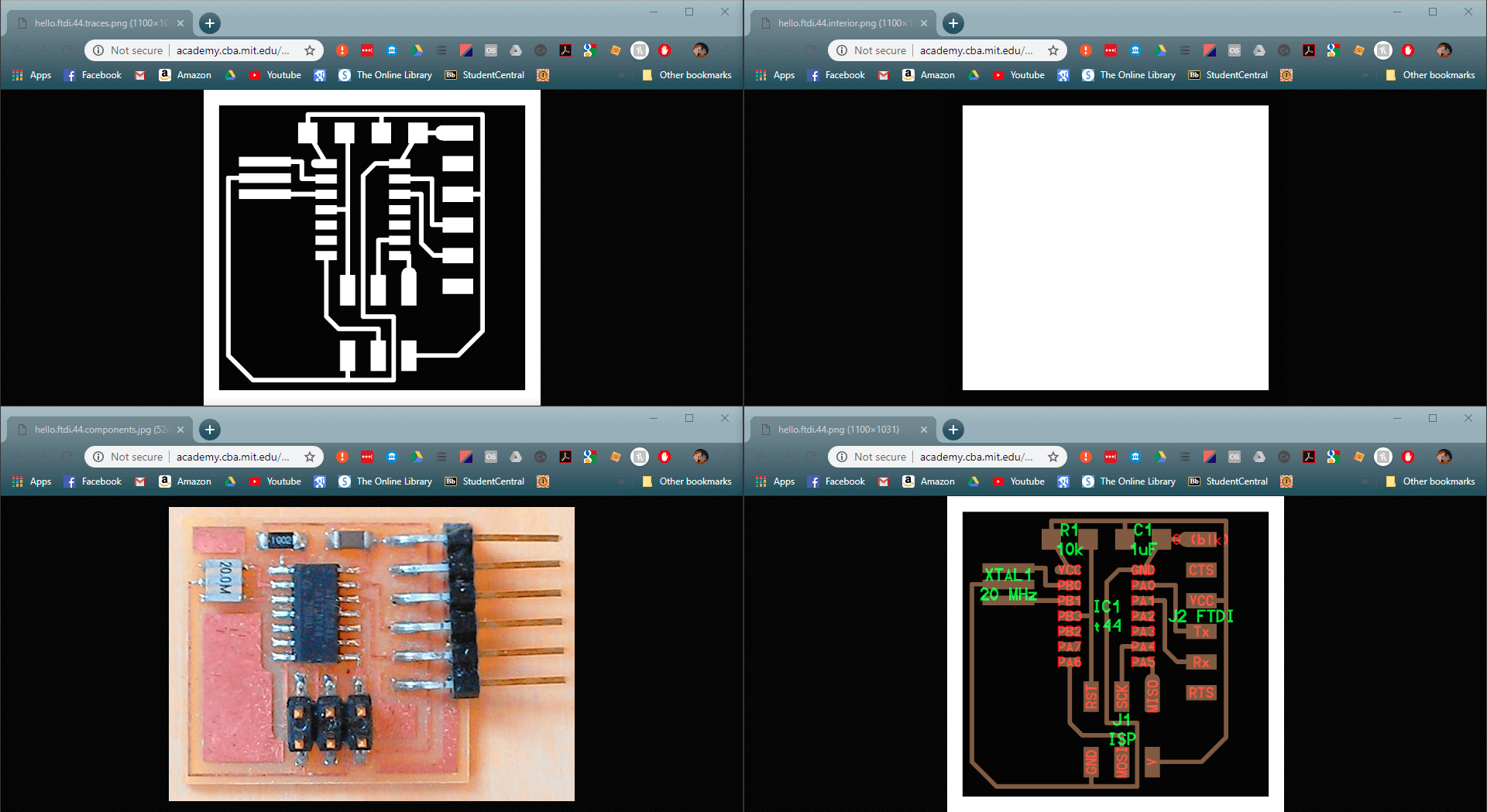
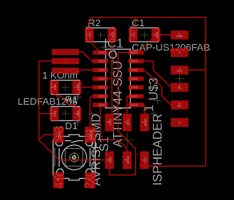
These are the example files for the board, it is required to add at least an LED and a button.
Andrew Sleigh at Fablab Brighton created this Eagle tutorial which is presented at exactly the pace required; with the answer to my next question right in the next section almost everytime.
The only addition I think would be about recreating the board frame if you accidently delete it because you didn't realise that's what that was.
After a google I think that the board outline is created by lines on layer 20, but it appears that they can be added later in Illustrator anyway so I don't think it matters too much.
As usual I started documenting through screenshots later than the begining, although the content of the images will be largely the same as in the link above.
From a previous foray into Eagle the Fab library was alread set up, but with my reading courtesy of Andrew I knew what I was going in to do.
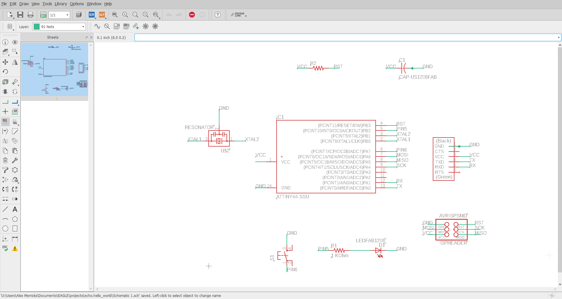
I started by adding all the parts that I collected together to do the drawing, the images in the tutorial might be slightly confusing with inconsistent numbers of resistors; but Consistent inconsistent aesthetic relativity.
I then followed through the tutorial to the conclusion that labelling all of the pins made the most sense rather than trying to link them all together with lines and junctions (that seemed a lot of things to keep track of)
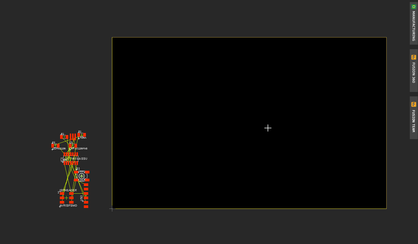
I then opened the board screen, which links the parts with airlines in preparation for routing.
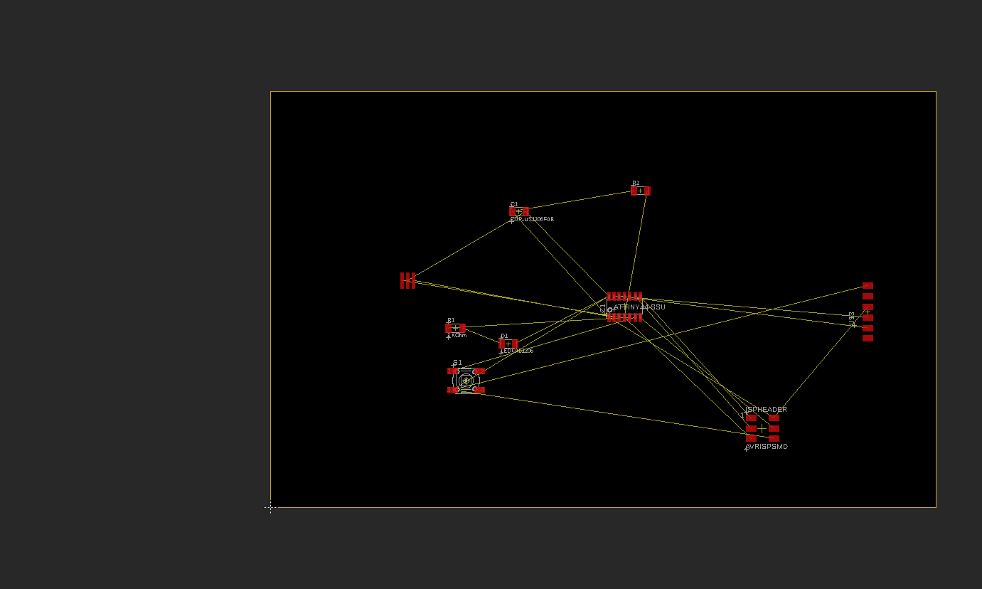
I then rearranged the parts to get a better idea of what was going on. Rotated them to the correct orientations and then joined the relevant pads together (the software really does most of it it would seem).
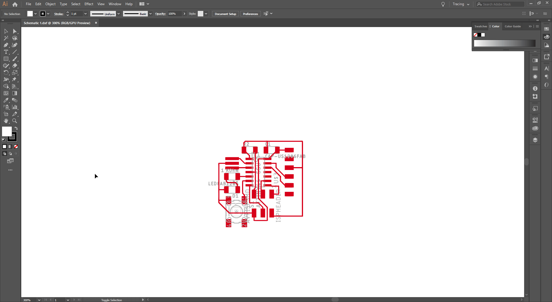
I then exported it as a DXF to import to Illustrator to create the png's required to create the machine code.
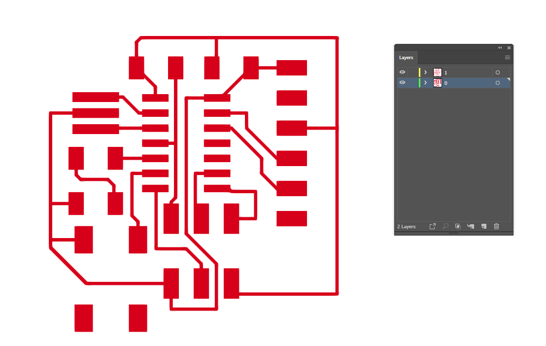
After importing, I cleaned out the unnecessary layers, and consolidated the pads and traces.
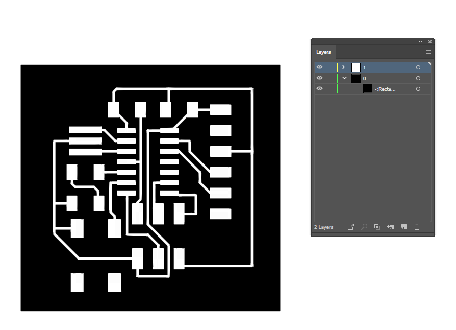
Preparing for exporting, I then add a greyscae backplate to see what was going on with the white colours.
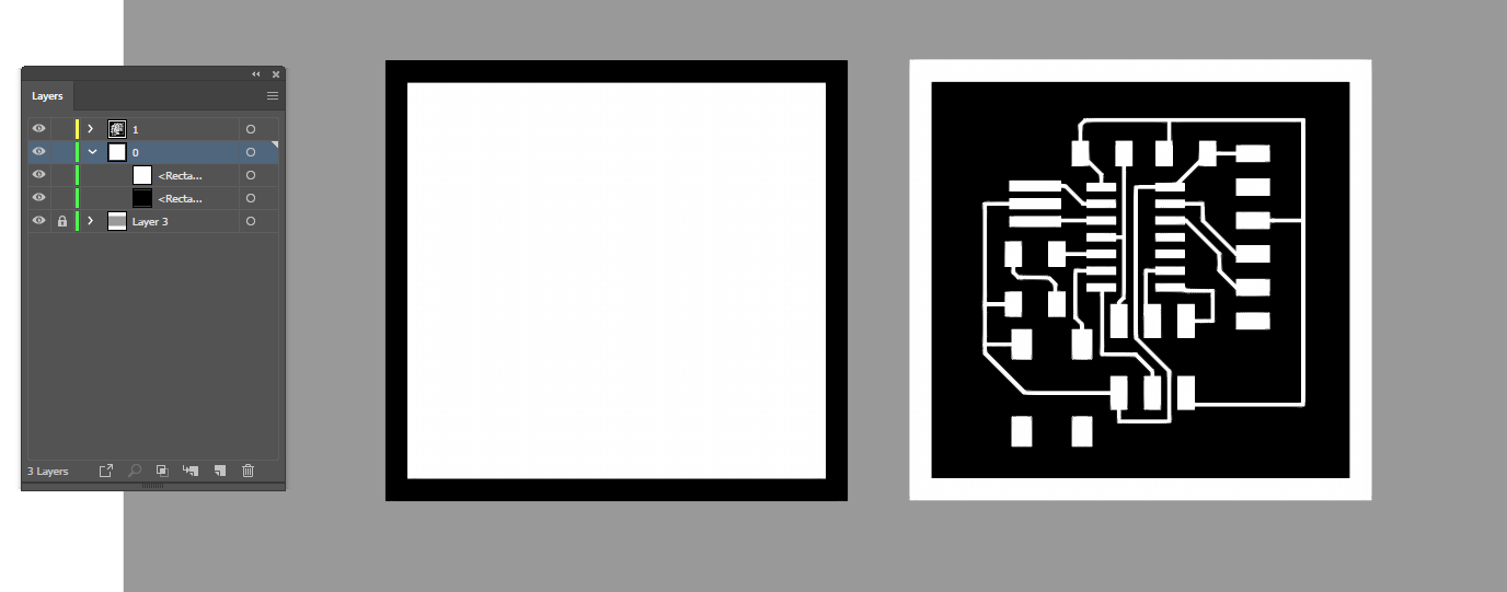
I copy moved the background part and inverted the colours to create the traces and outline backparts for cutting out the board.
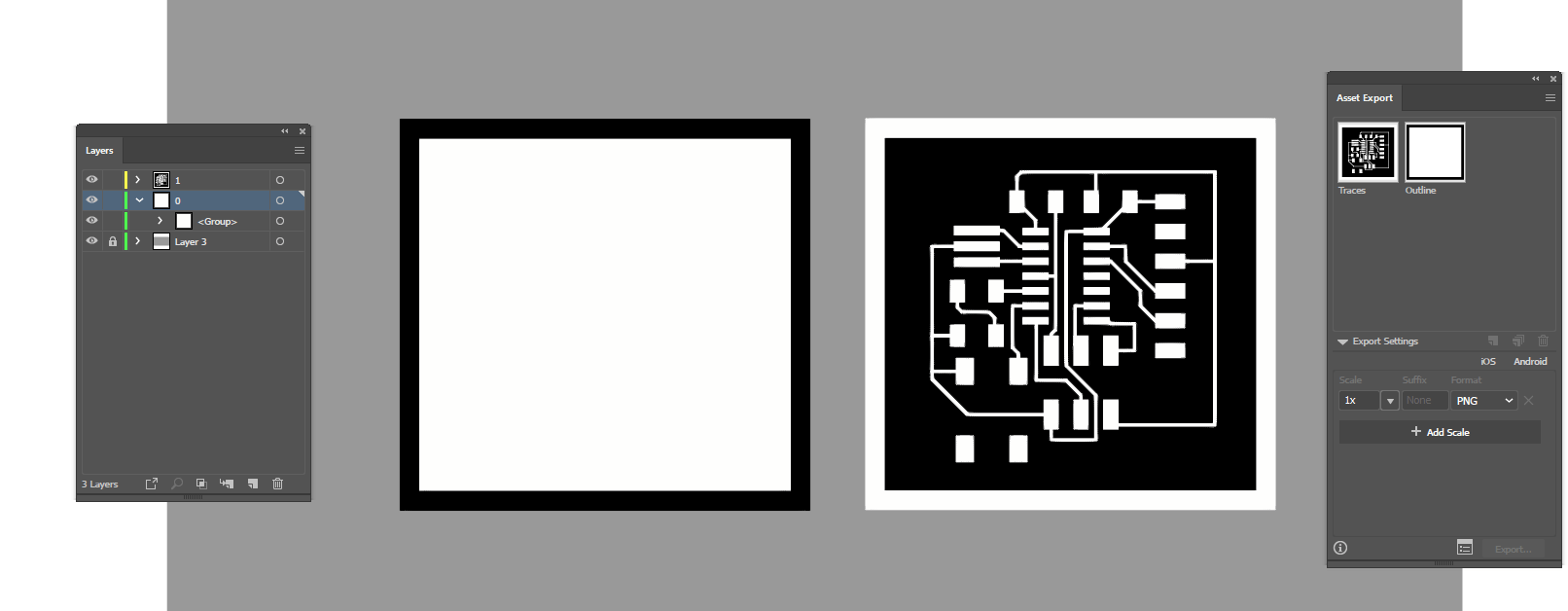
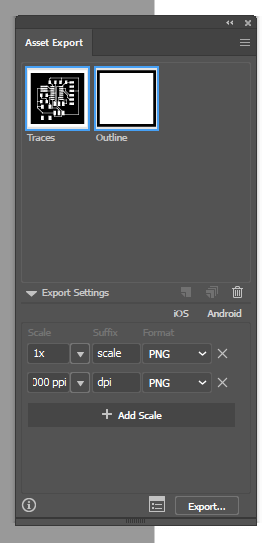
I had issues with exporting and resolution with my previous attempts at making the board, so I am exporting it with different 'methods' to see whether there is an issue there
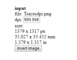
The 1000 dpi seems to be the correct size, and the quality of the preview image is as expected
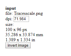
this is the one exported at scale - the quality of the preview image is very reduced, however the size is the same this time.
Piece size is a product of image dpi and dpi scaling option in fabmodules. (Note: the fabacademy appear to want to switch to mods over fabmodules - I just like how fabmodules is put together)
With the .rml files created all that is required is to head to the lab and get milling.