Week 7 - Electronics Design - Part 1 - hand made?
Redraw the Echo hello-world Board
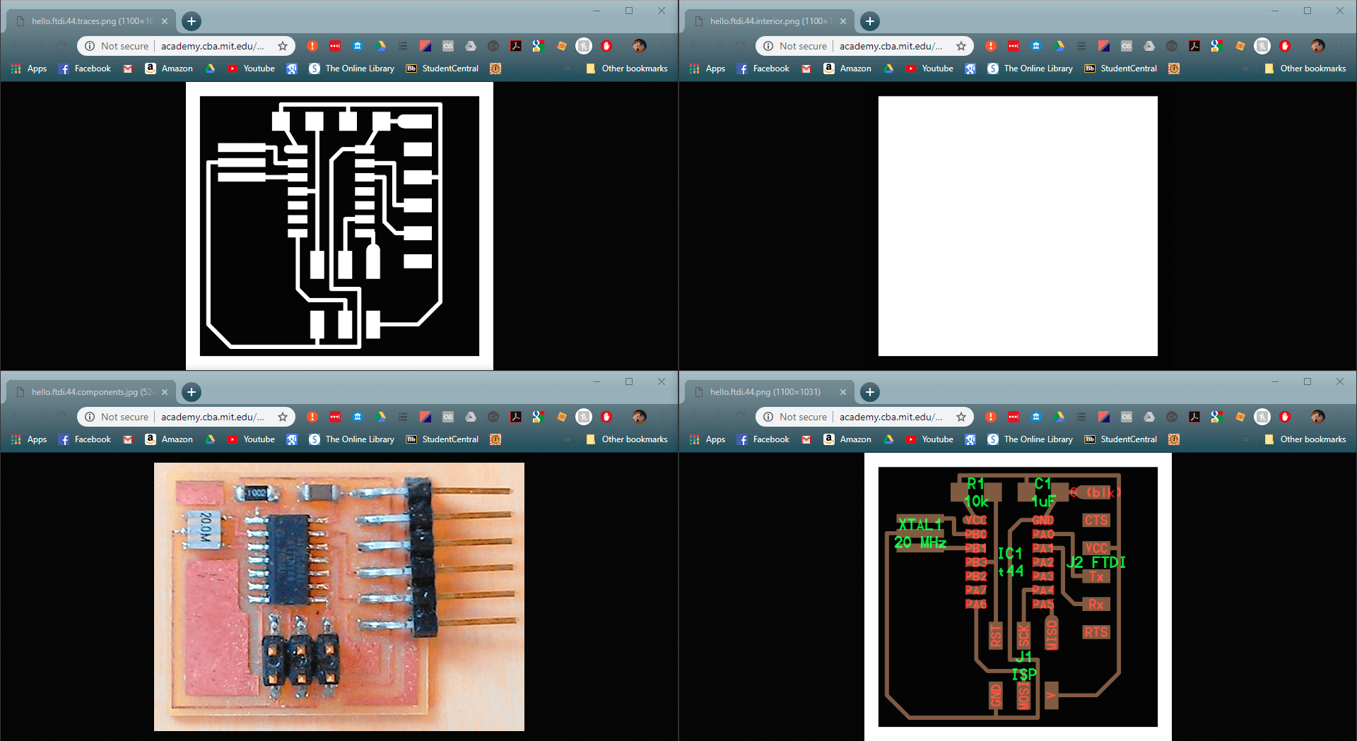
These are the example files for the board, it is required to add at least an LED and a button.
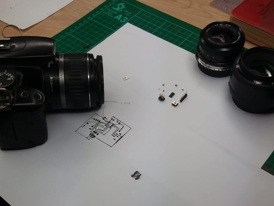
I used the physical parts as a guide to draw out the circuit
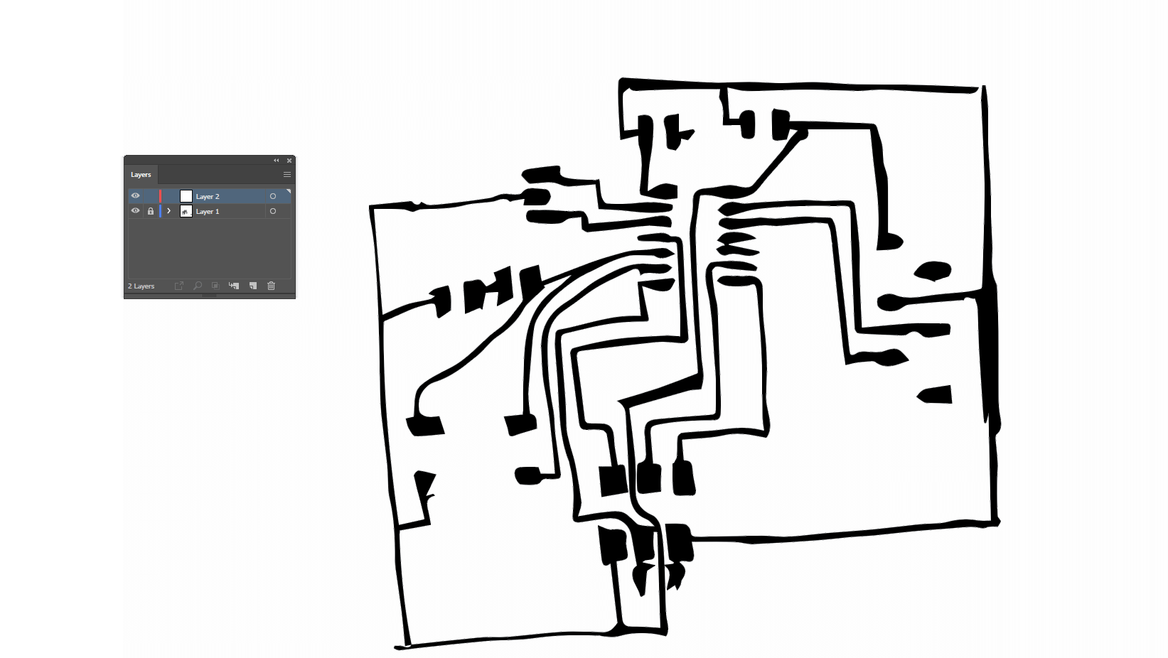
I then scanned the drawing for conversion using Illustrator into pngs for fabmodules
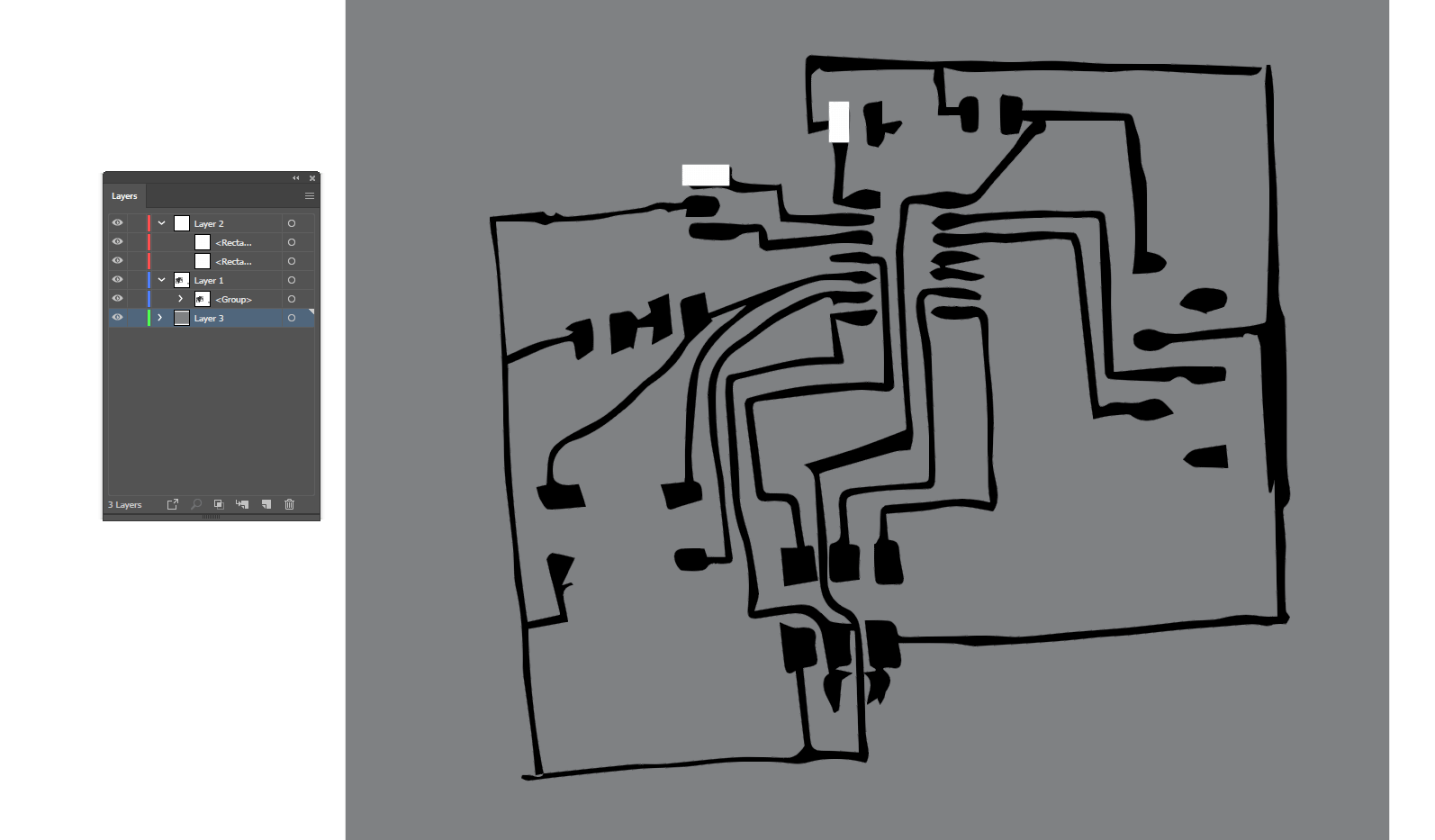
I started by adding specific sized rectangles to the places they were going to be needed (disregarding the fact that most pads are sized for the specific part)
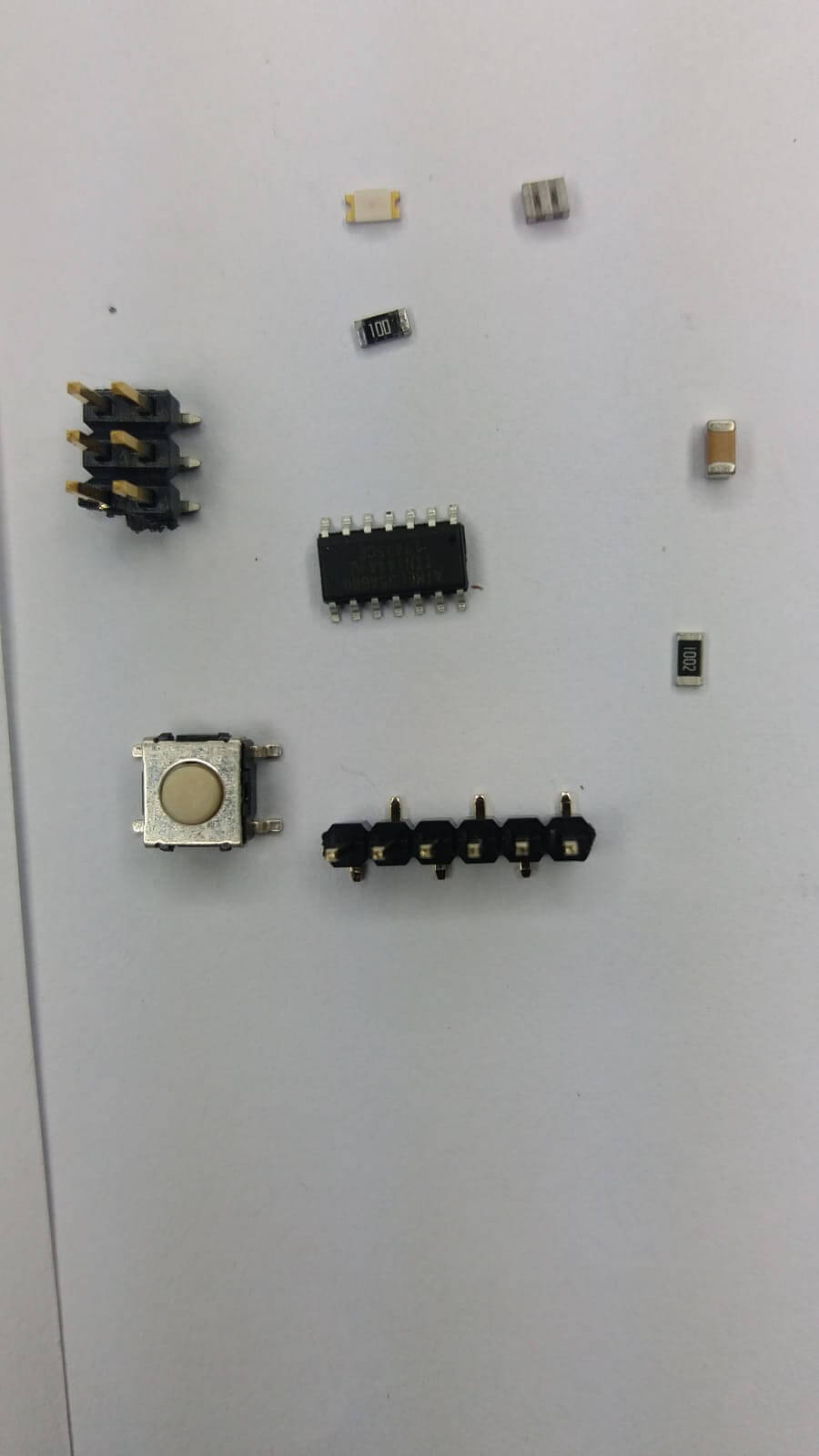
the parts in place
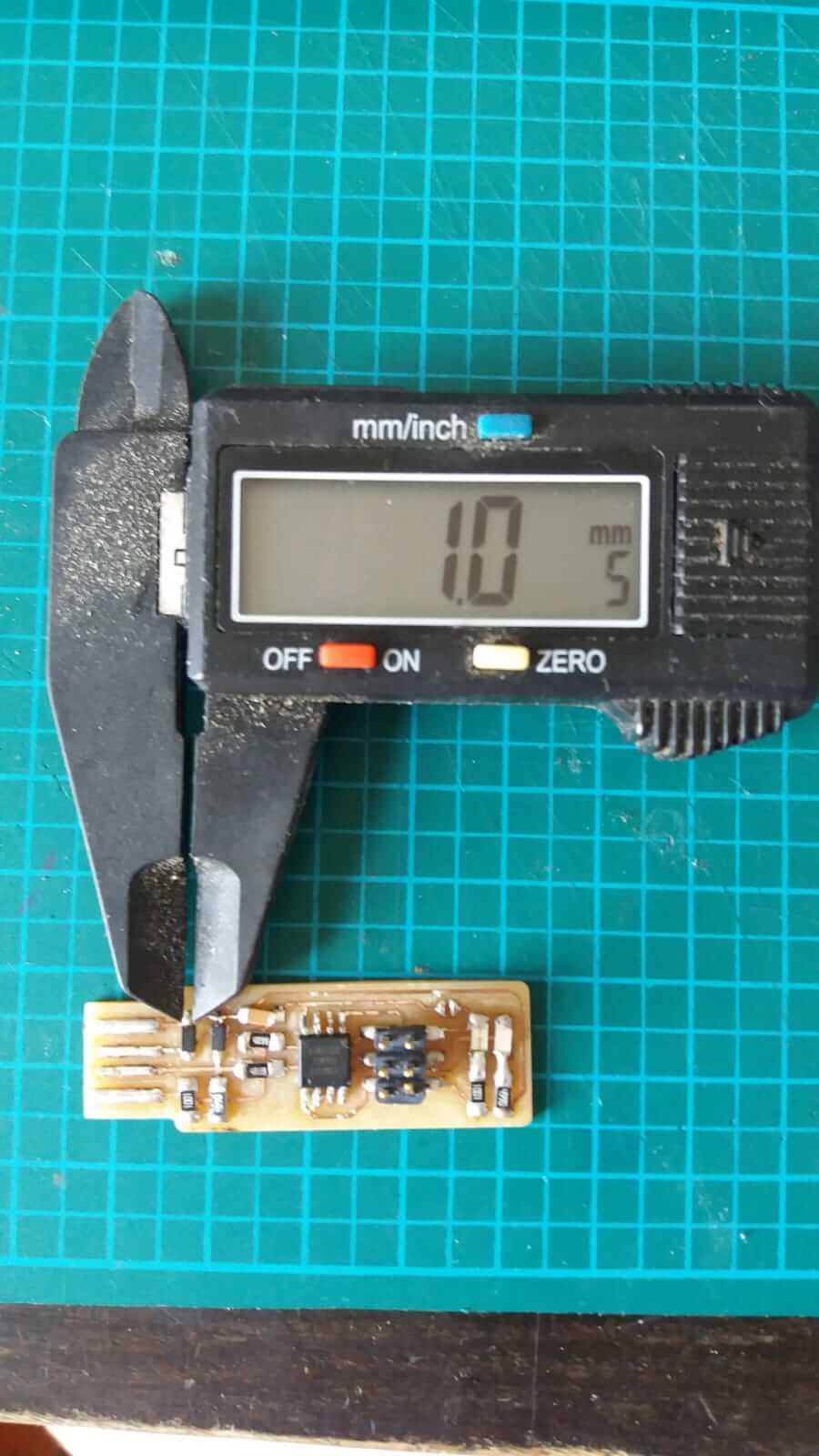
Measuring the pads
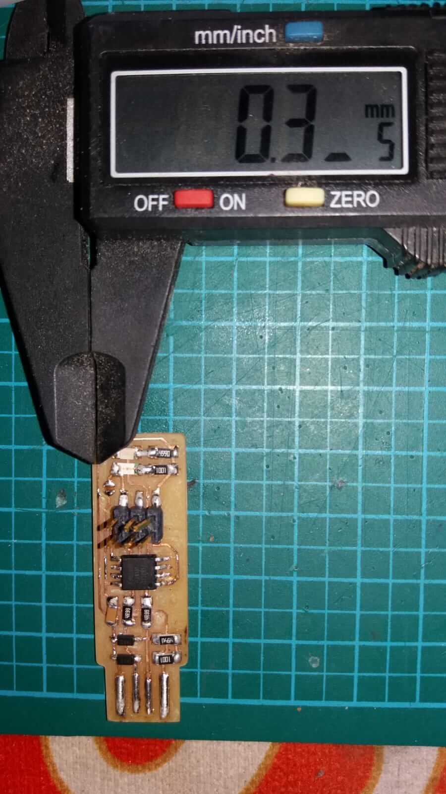
Measuring the traces
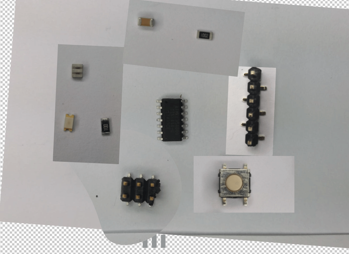
I created a top down collage of the parts to make drawing the circuit 'easier'
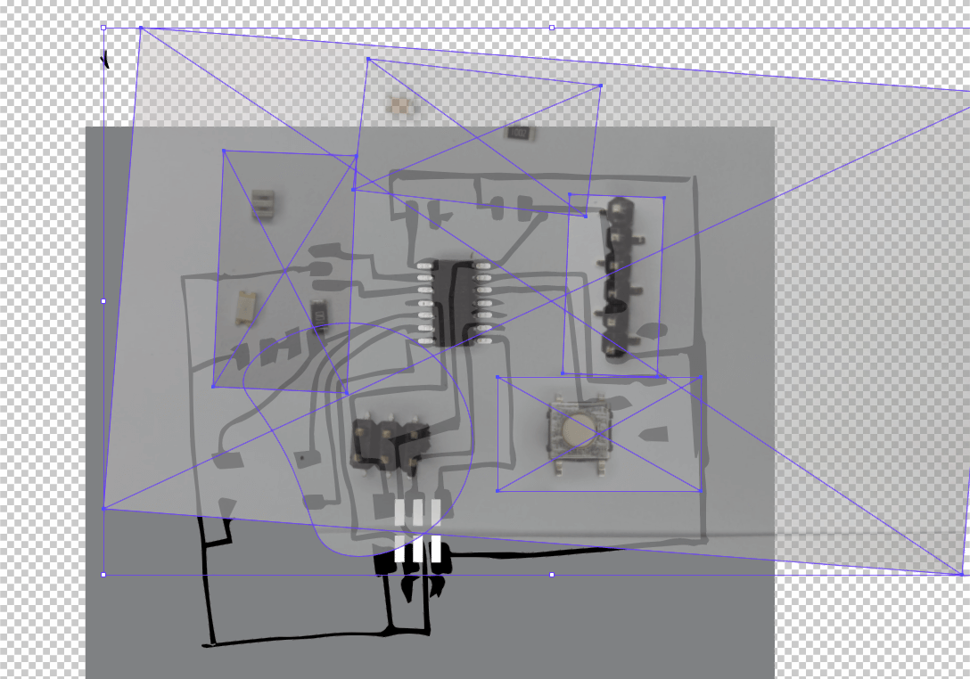
I tried overlaying what I had created thus far to not much avail
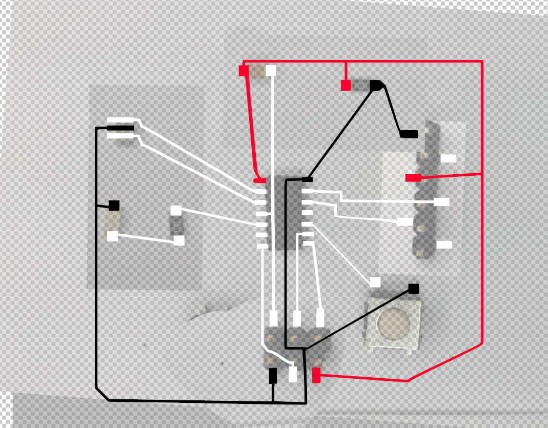
And I just continued down this broken route for far too long
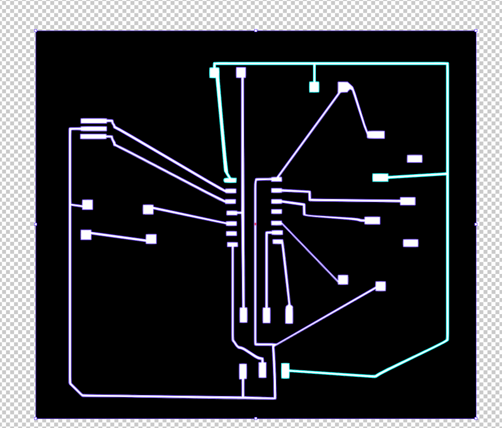
Like way too long
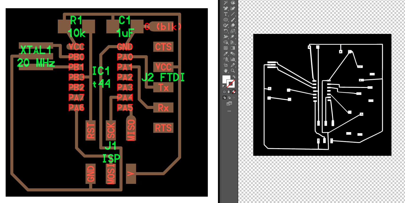
But I did end up with a png file I could try in fabmodules (which failed spectacularly because I hadn't considered anything about it really)
In conclusion - use the software people spent a very long time building, it's easier and less problem and disaster ridden. (This is although something I want to come back to for my final project I think)
I decided to abandon this 'version' of the board, as I was expecting to run into many milling errors or other related issues throught the manufacturing process.
I therefore decided to redraw the board in illustrator using the example board as a background to work on.
I also made a camera remote this week
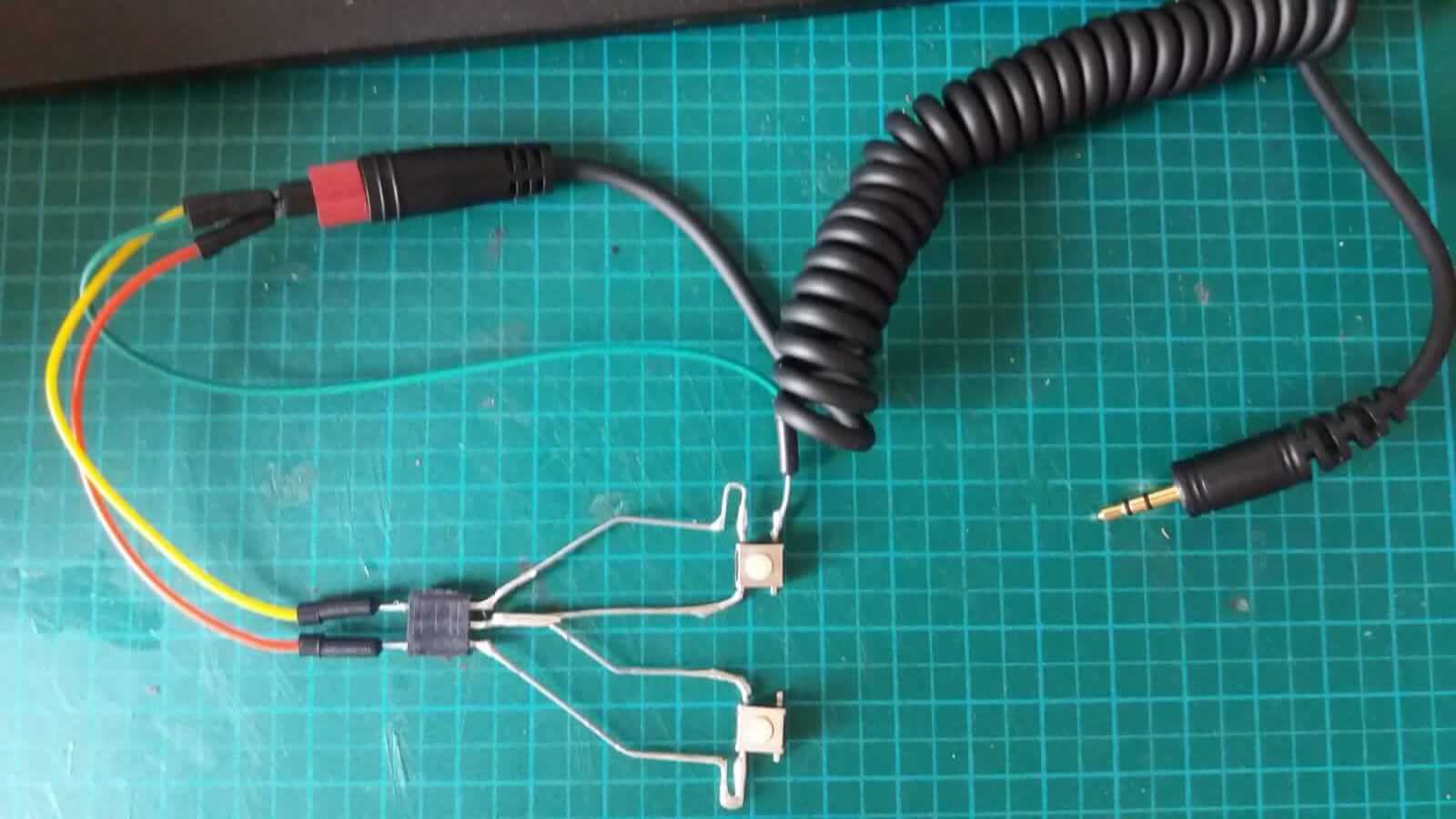
One of the buttons triggers the focus ring, the second butter in conjunction with the first button triggers the shutter.
This configuration of the button legs didn't fuction as required, I rearranged the legs and pins, such that there is now a focus button and a shutter release button, which are independent.
The first button shorts the focus line to ground, the shutter button shorts both the focus line and shutter line to ground.