18. Wildcard week
- This week objective was to Design and produce something with a digital fabrication process (incorporating computer-aided design and manufacturing) not covered in another assignment, documenting the requirements that your assignment meets, and including everything necessary to reproduce it. Possibilities include (but are not limited to) composites, textiles,biotechnology, robotics, and cooking.
- Out of the topic what Neil shared i wanted to try out Robotics
- I decided to build a line following robot
- For digital manufacturing process i decided to design few parts that would be used in my robot
Research and Useful links
As robotics was a completely new field for me, i spent some time understanding it first. Robotics field is vast and find its implementation in various fields space, medical, industry, agriculture.
Understanding Robotics
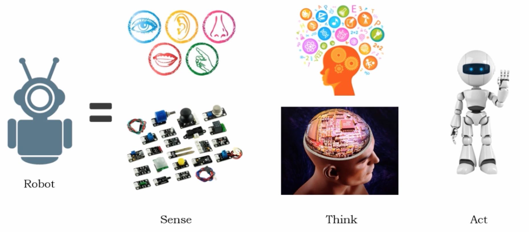
Below image explain so basically its a machine that sense its environment and then do some calculation and act.
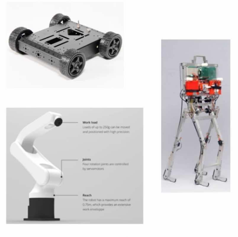
Key parts of Robot
Structure
- Chassis (mechanical structure)
- Locomotion (wheels)
Input
- Sensor systems
Brain
- Microcontroller systems e.g Arduino
- Programming
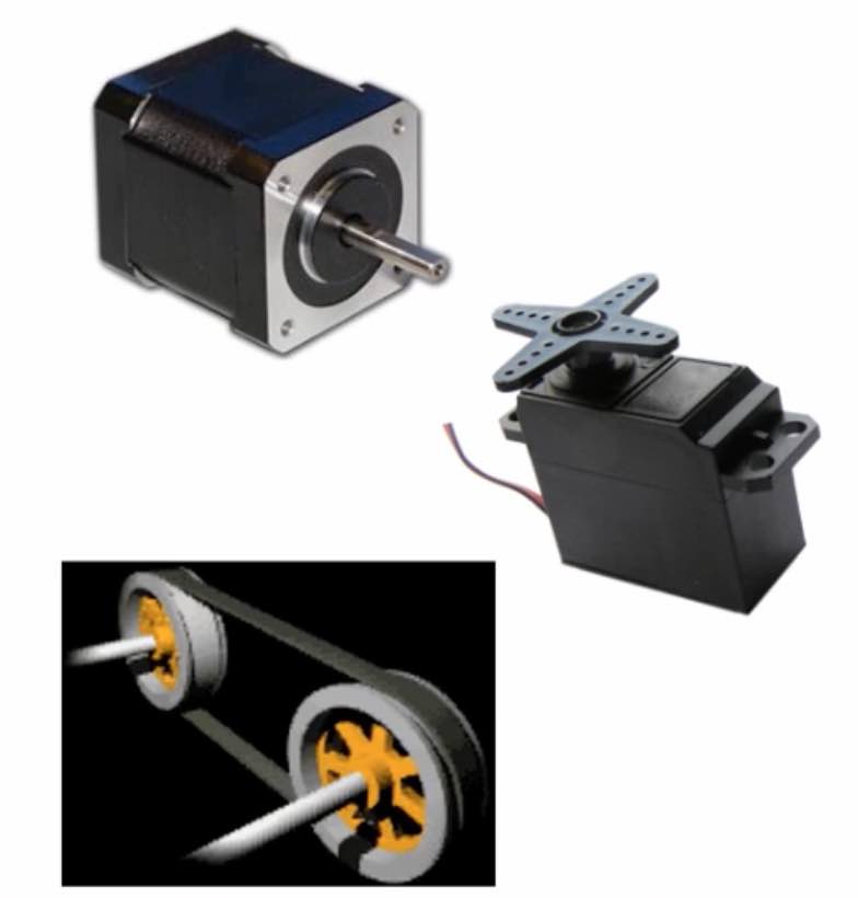
Output
- Motor/Actuators
- Driver Mechanism
Build a Line following robot
The robots in industries perform a lot of tasks, including the material handling. To automate the process of material handling, the robot has to be guided properly and using a dedicated vision system or coding the co-ordinates is not feasible. The simplest solution, paint colour strips on the floor for the robot to follow, this deals with the transportation of materials. The material slots can also be colour coded to allow the robot to distinguish. So i decided to build one in this week. As mentioned above we have key parts that are required for robot to function.
Structure
One of the mechanical aspect for Robot is the Chassis and locomotion.
Chassis
For chassis i simply used pieces of plywood and used screws to tie them together.
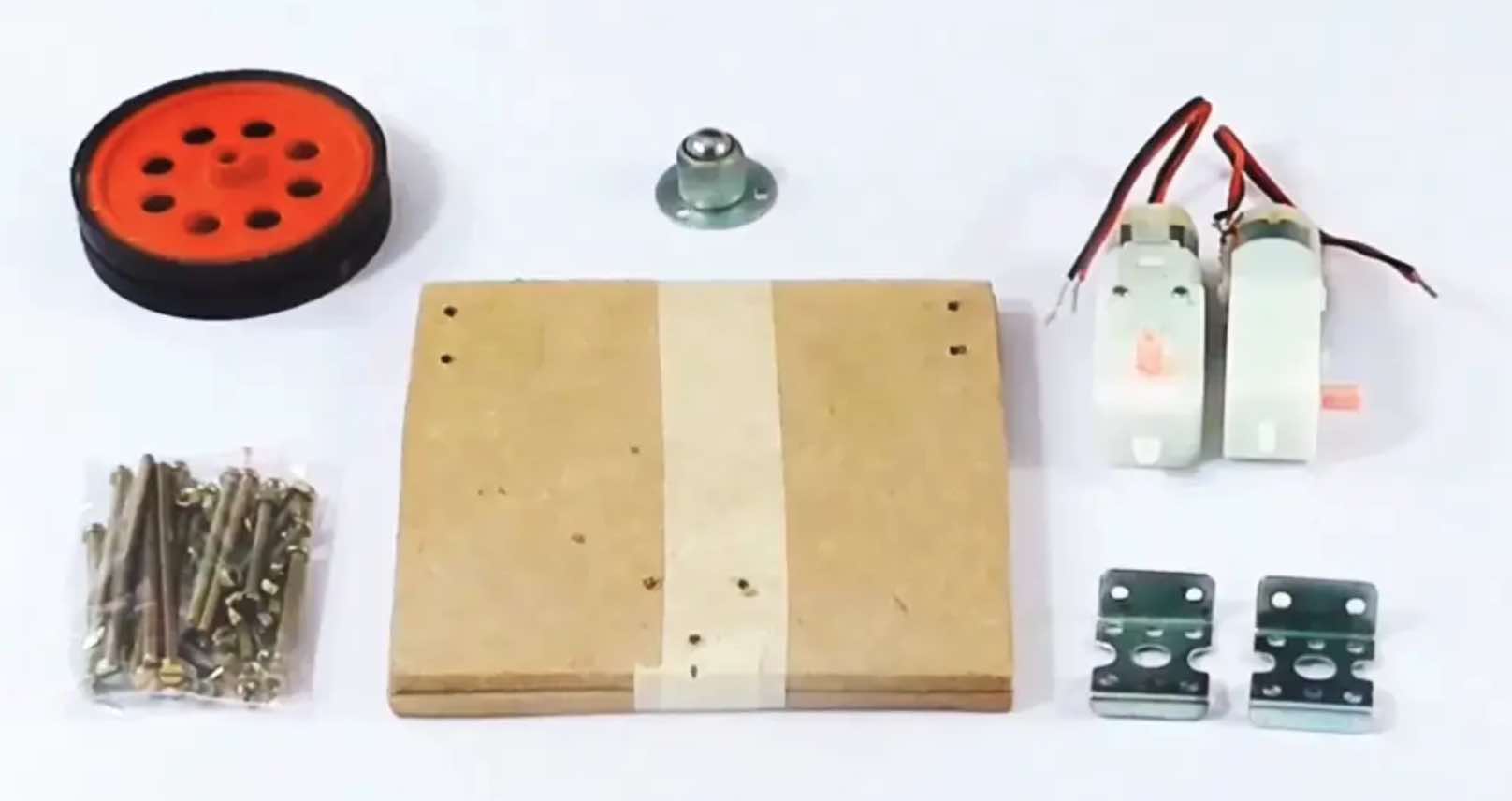
Locomotion
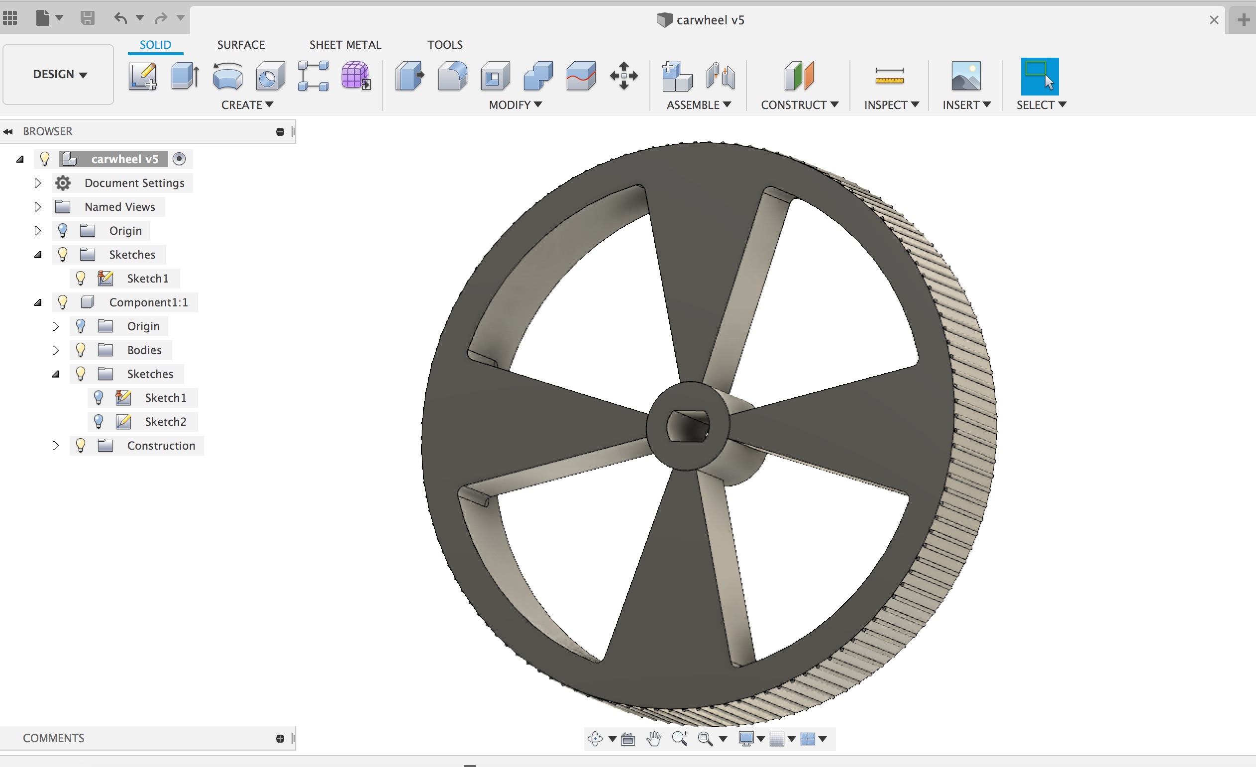
In 3d printing week i already designed the wheels.
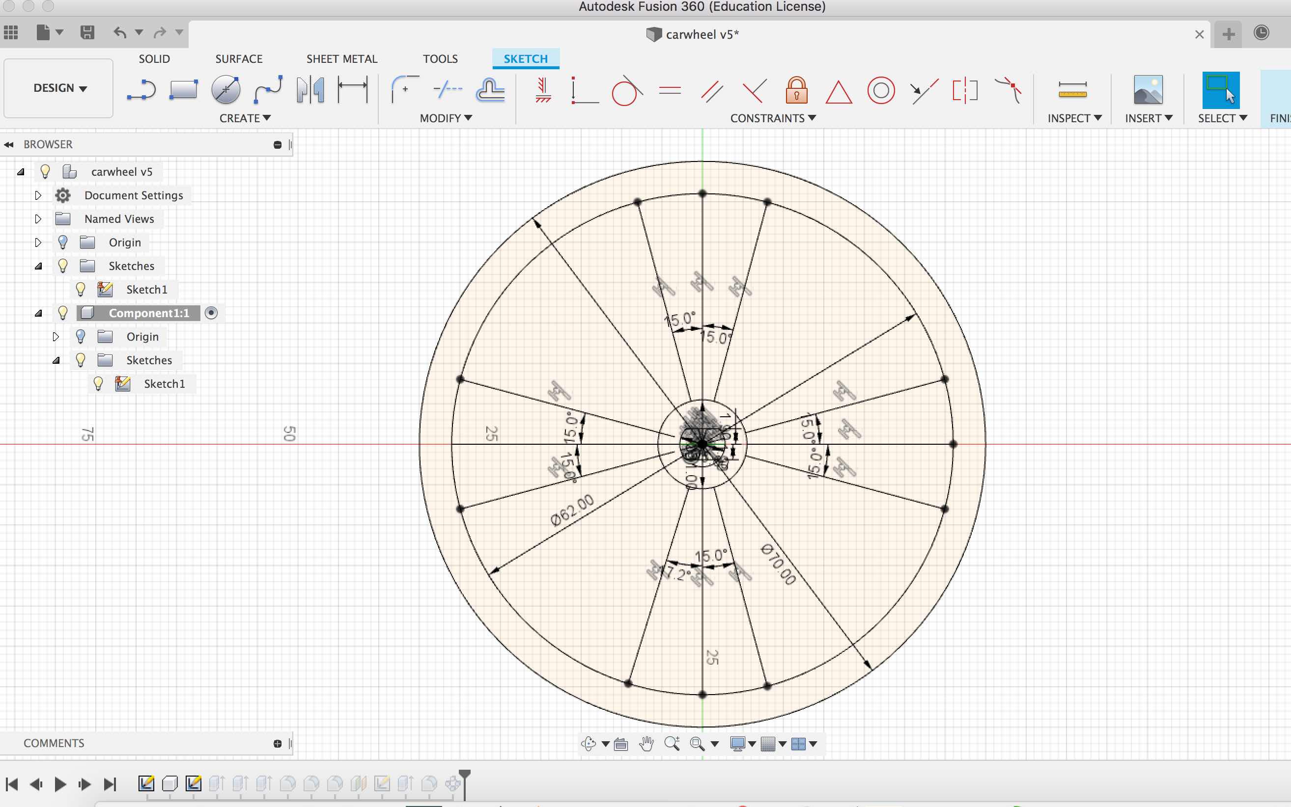
In Summary
- I started with 2d sketch to draw circle
- Used extrusion command to create wheel pattern
- For the tyre pattern on the wheel i first created an offset plane and then used the create circular pattern
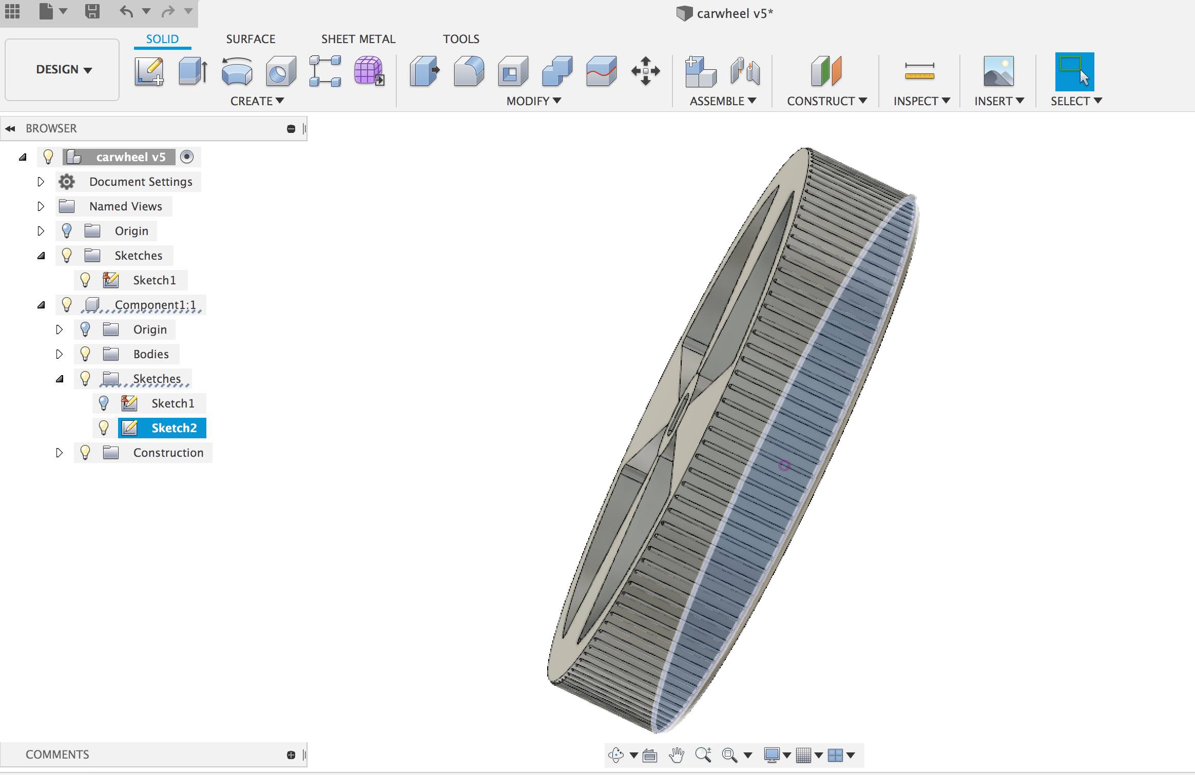
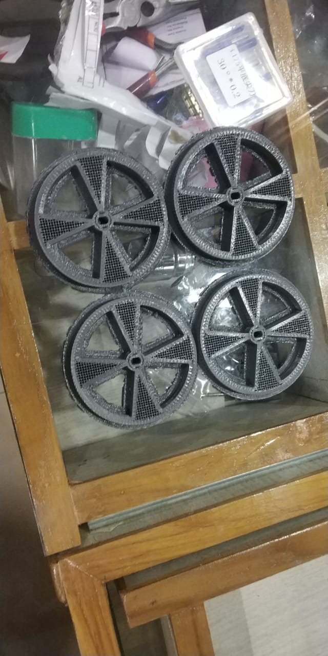
3d Print Wheel Final Outcome
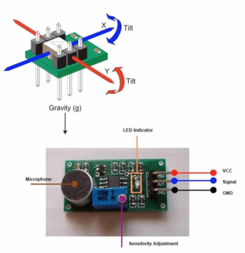
Input
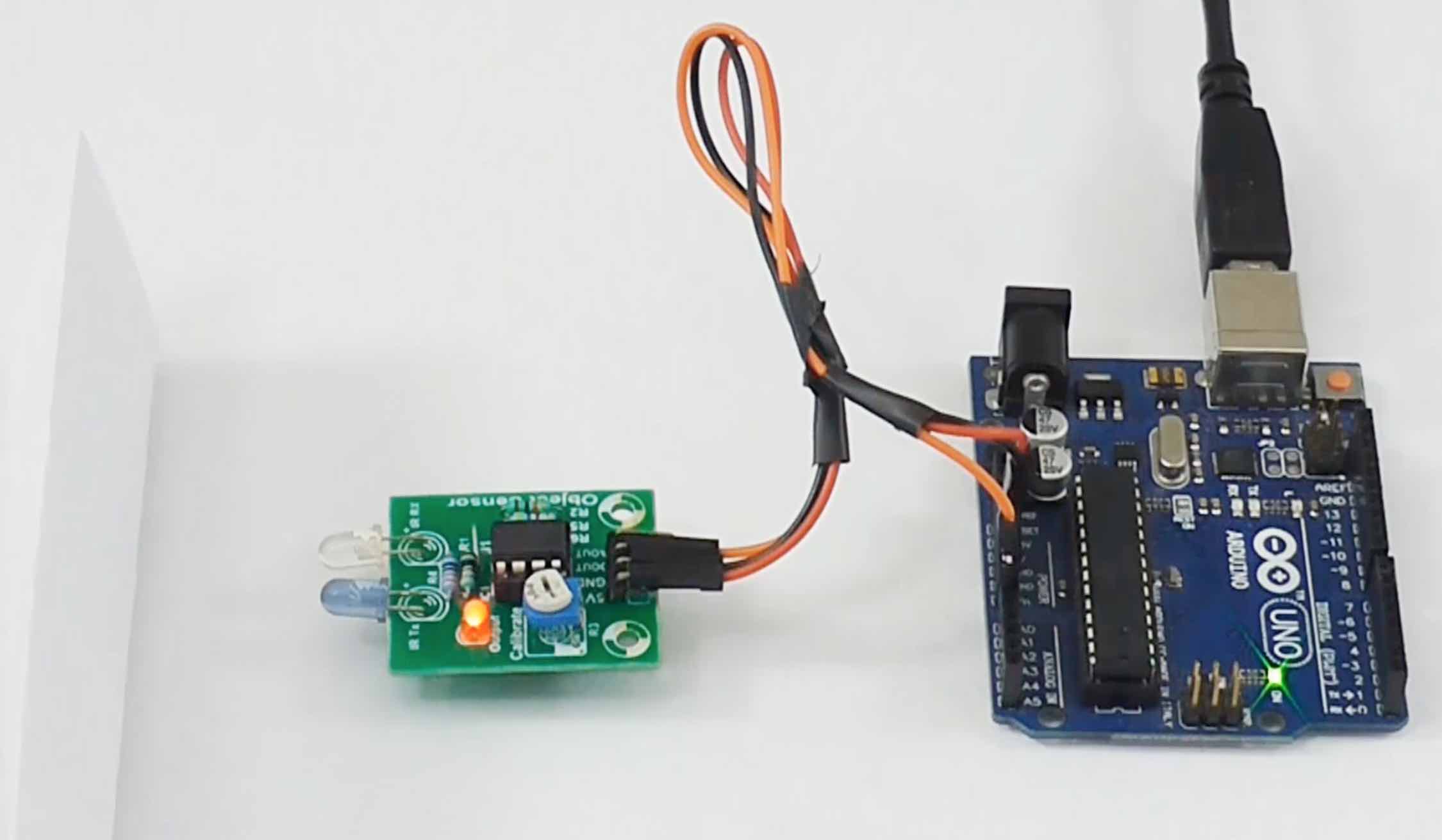
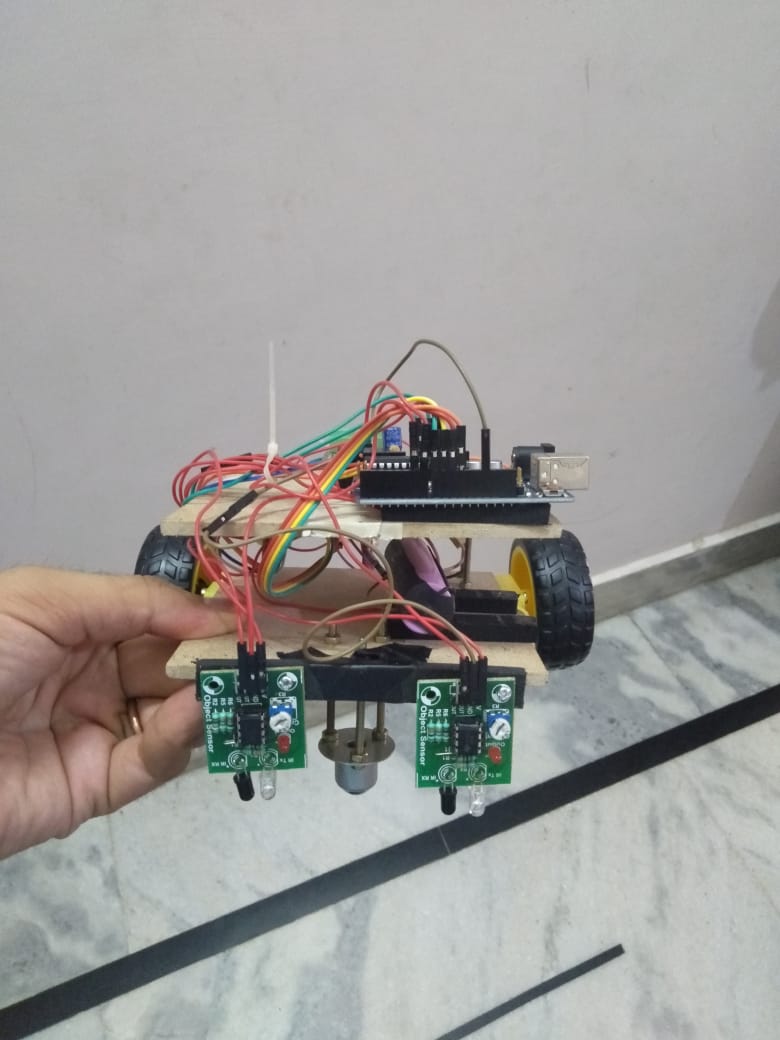
For line following Robot i decided to use Object detection sensor.
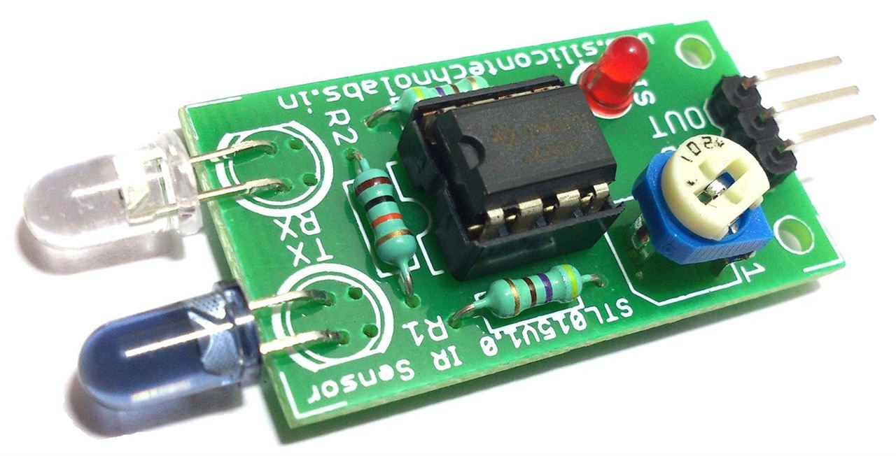
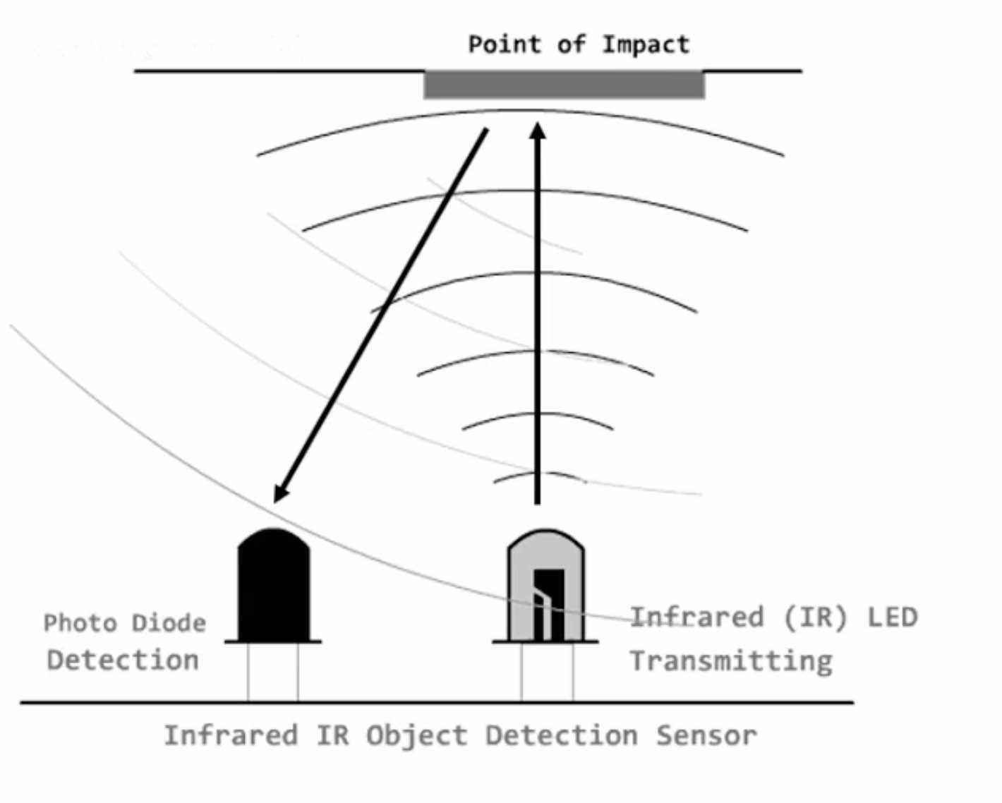
First i understood how this sensor work and how to interface it with Arduino. Basically it has an IR transmitting diode and photo detection diode. It has 4 pins
- VCC
- GND
- Digital Output (which can be interfaced with Arduino to read its value)
- Analog Output (which can be interfaced with Arduino to read its value)
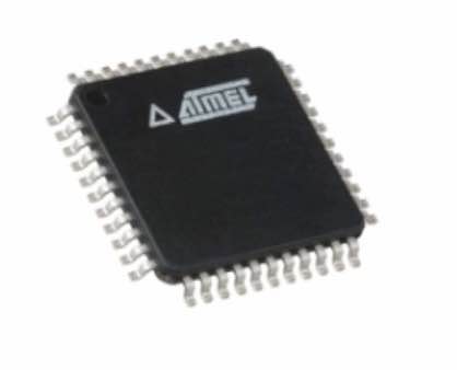
Brain
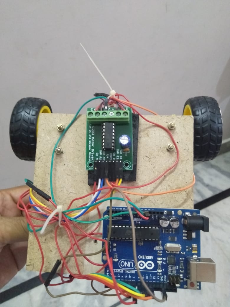
I decided to use Arduino UNO for this project. Because of the time constraints i decided to use prefabricated boards and motor driver. Later i can replace it with Satshakit and build my own drivers as the design would be compatible.
Output
-
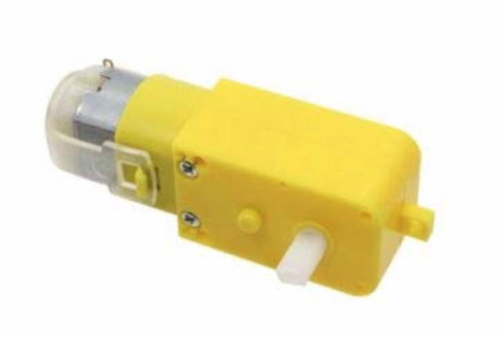
To drive my line follower robot i ordered DC gear Motor.
-
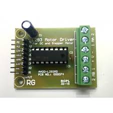
We also need motor driver L293 so i used that to drive the above DC motors
-
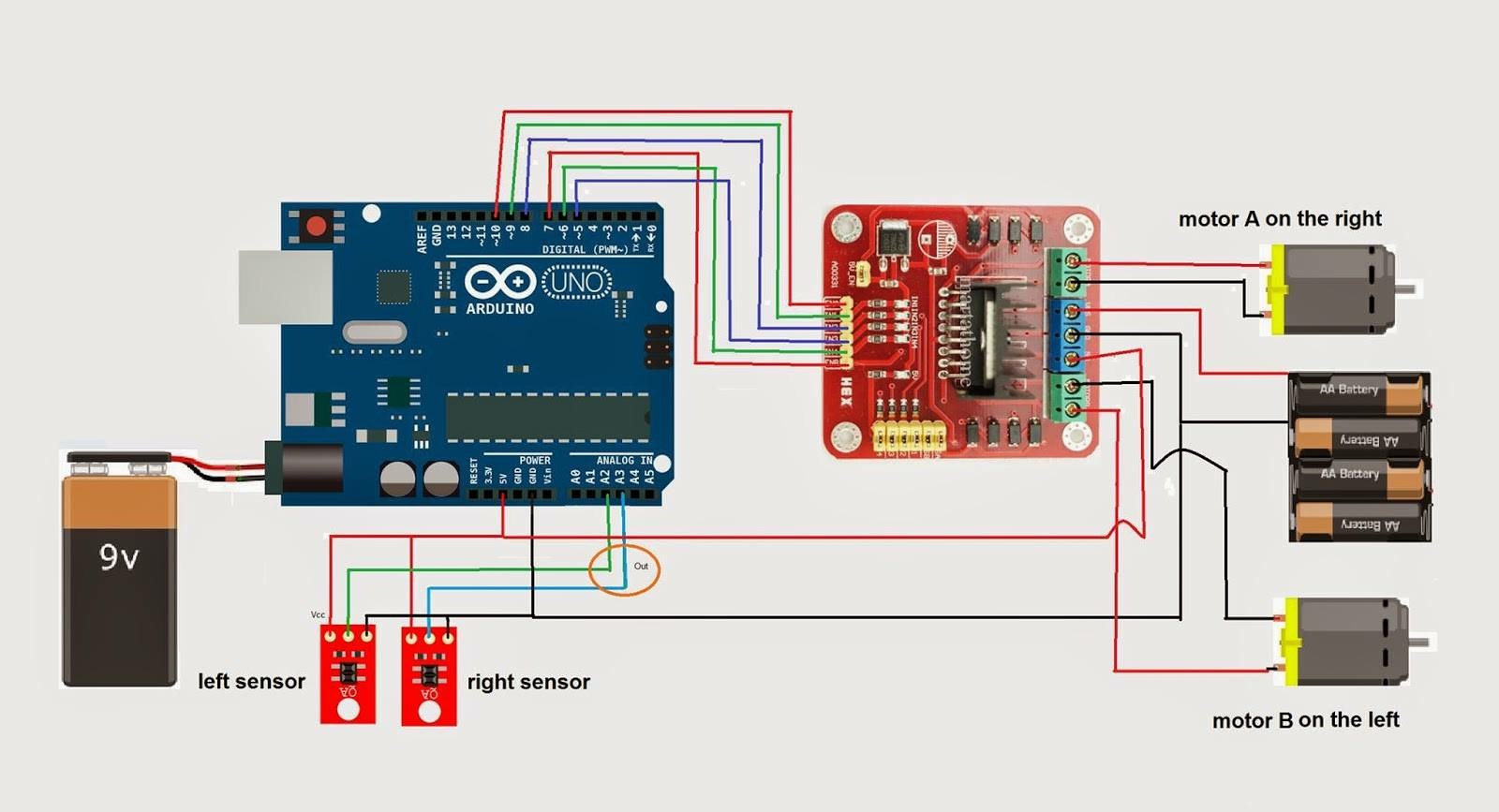
The below diagram shows how to connect motors, Driver and Arduino
Final Assembly
Code For Microcontroller For Line following Robot
- Sense the line
- Based on sensor input decide to rotate motors
/*------ Arduino Line Follower Code----- */

/*-------definning Inputs------*/
#define LS 6      // left sensor
#define RS 7      // right sensor

/*-------definning Outputs------*/
#define LM1 10       // left motor
#define LM2 11      // left motor
#define RM1 8       // right motor
#define RM2 9       // right motor

void setup()
{
  pinMode(LS, INPUT);
  pinMode(RS, INPUT);
  pinMode(LM1, OUTPUT);
  pinMode(LM2, OUTPUT);
  pinMode(RM1, OUTPUT);
  pinMode(RM2, OUTPUT);
}

void loop()
{
  if(digitalRead(LS) && digitalRead(RS))     // Move Forward
  {
    digitalWrite(LM1, HIGH);
    digitalWrite(LM2, LOW);
    digitalWrite(RM1, HIGH);
    digitalWrite(RM2, LOW);
  }

  if(!(digitalRead(LS)) && digitalRead(RS))     // Turn right
  {
    digitalWrite(LM1, LOW);
    digitalWrite(LM2, LOW);
    digitalWrite(RM1, HIGH);
    digitalWrite(RM2, LOW);
  }

  if(digitalRead(LS) && !(digitalRead(RS)))     // turn left
  {
    digitalWrite(LM1, HIGH);
    digitalWrite(LM2, LOW);
    digitalWrite(RM1, LOW);
    digitalWrite(RM2, LOW);
  }

  if(!(digitalRead(LS)) && !(digitalRead(RS)))     // stop
  {
    digitalWrite(LM1, LOW);
    digitalWrite(LM2, LOW);
    digitalWrite(RM1, LOW);
    digitalWrite(RM2, LOW);
  }
}
Demo Line Follower Robot
-
Caliberating the sensor to detect the black line
-
Test Run
Learnings and issues
- I was actually not very much clear on this week objectives so i raised an issue on gitlab and got following comment fron Neil
The goal of wildcard week is to explore digital fabrication processes that we haven’t previously covered. So, making a robot is great for a final project, but for wildcard week that wouldn’t count because what you describe is an application of previous processes. The intention for including robotics in wildcard week is to use robots (either one you make or a commercial one) to do a fabrication processes. There are many options for those – assembly, extrusion, deposition, multi-axis machining, … .
- So it means i have to start again for the week, but i learnt a great deal about robotics and was able to build one. This also could have been a final week project for me to build with sensors prepared in input week, mechanical design to build chassis , 3d printed wheels and a bluetooth interface to drive my car.Though at one point i felt like below but Neil was pretty clear on objectives of this week. So its time that i get started again.

-
This part of week does not qualify for the weekly assignment but at least for my kids they got a cool toy to play around so i am pleased with the outcome
-
Another thing i wanted to try was a Robotic Arm, but as the constraints was to do a fabrication process using Robotics. As i am planning to graduate so i decided not to go that wild in this week. So because of time constraints i picked up composites to cover this week assignment.
Composites
Introduction to Composites (from Wikipedia)
-
A composite material (also called a composition material or shortened to composite, which is the common name) is a material made from two or more constituent materials with significantly different physical or chemical properties that, when combined, produce a material with characteristics different from the individual components. The individual components remain separate and distinct within the finished structure, differentiating composites from mixtures and solid solutions.
-
Composites are made up of individual materials referred to as constituent materials. There are two main categories of constituent materials: matrix (binder) and reinforcement. At least one portion of each type is required. The matrix material surrounds and supports the reinforcement materials by maintaining their relative positions. The reinforcements impart their special mechanical and physical properties to enhance the matrix properties. A synergism produces material properties unavailable from the individual constituent materials, while the wide variety of matrix and strengthening materials allows the designer of the product or structure to choose an optimum combination.
-
Engineered composite materials must be formed to shape. The matrix material can be introduced to the reinforcement before or after the reinforcement material is placed into the mould cavity or onto the mould surface. The matrix material experiences a melding event, after which the part shape is essentially set. Depending upon the nature of the matrix material, this melding event can occur in various ways such as chemical polymerization for a thermoset polymer matrix, or solidification from the melted state for a thermoplastic polymer matrix composite.
When Should you use Composites ?
As with all engineering materials, composites have particular strengths and weaknesses, which should be considered at the specifying stage. Composites are by no means the right material for every job. However, a major driving force behind the development of composites has been that the combination of the reinforcement and the matrix can be changed to meet the required final properties of a component. For example, if the final component needs to be fire-resistant, a fire-retardant matrix can be used in the development stage so that it has this property.
Weight reduction
- The primary reason composites are chosen is improved specific strength / stiffness (strength / stiffness specific per unit weight).
- This helps to reduce fuel use, or increase acceleration or range in transport.
- It allows for easier, faster installation or faster movement of robot arms and reduces supporting structures or foundations.
- It improves topside stability in vessels and offshore structures and buoyancy for deep sea applications. Durability and maintenance
- Composites don’t rust, which is crucial, especially in marine and chemical environments. The need for maintenance and painting is reduced or eliminated.
- Composite bearings for marine engines and bridges need no lubrication and don’t corrode.
- Combine the excellent fatigue resistance, and composites can increase product lifespan by several times in many applications.
Added functionality
- Composites are thermal insulators which is good for fire and blast protection or cryogenic applications.
- Electrical insulation is useful for railway lineside structures and radar transparency. A conductive mesh or coating can be integrated if needed, e.g. to reflect radar or divert lightning.
- Sensors, electronics and cabling can be embedded.
Design freedom
- Composites design allows for freedom of architectural form.
- Many parts can be consolidated into one, and stiffeners, inserts, etc. can be integrated in-mould.
- Composites can be tailored to suit the application by choosing the constituent materials and embedding extra functionality.
Let’s do some CAD
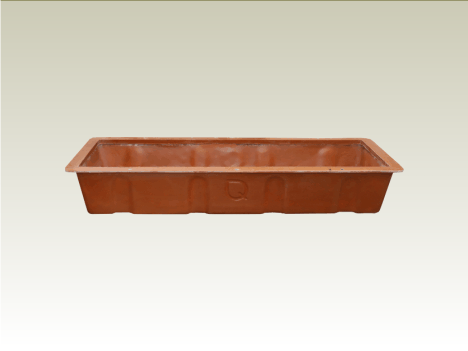
One of the thing for my project i was looking into was the GrowBed for hydroponics. So i decided to buid s simple growbed tray to try out composites.
Making Design in Fusion
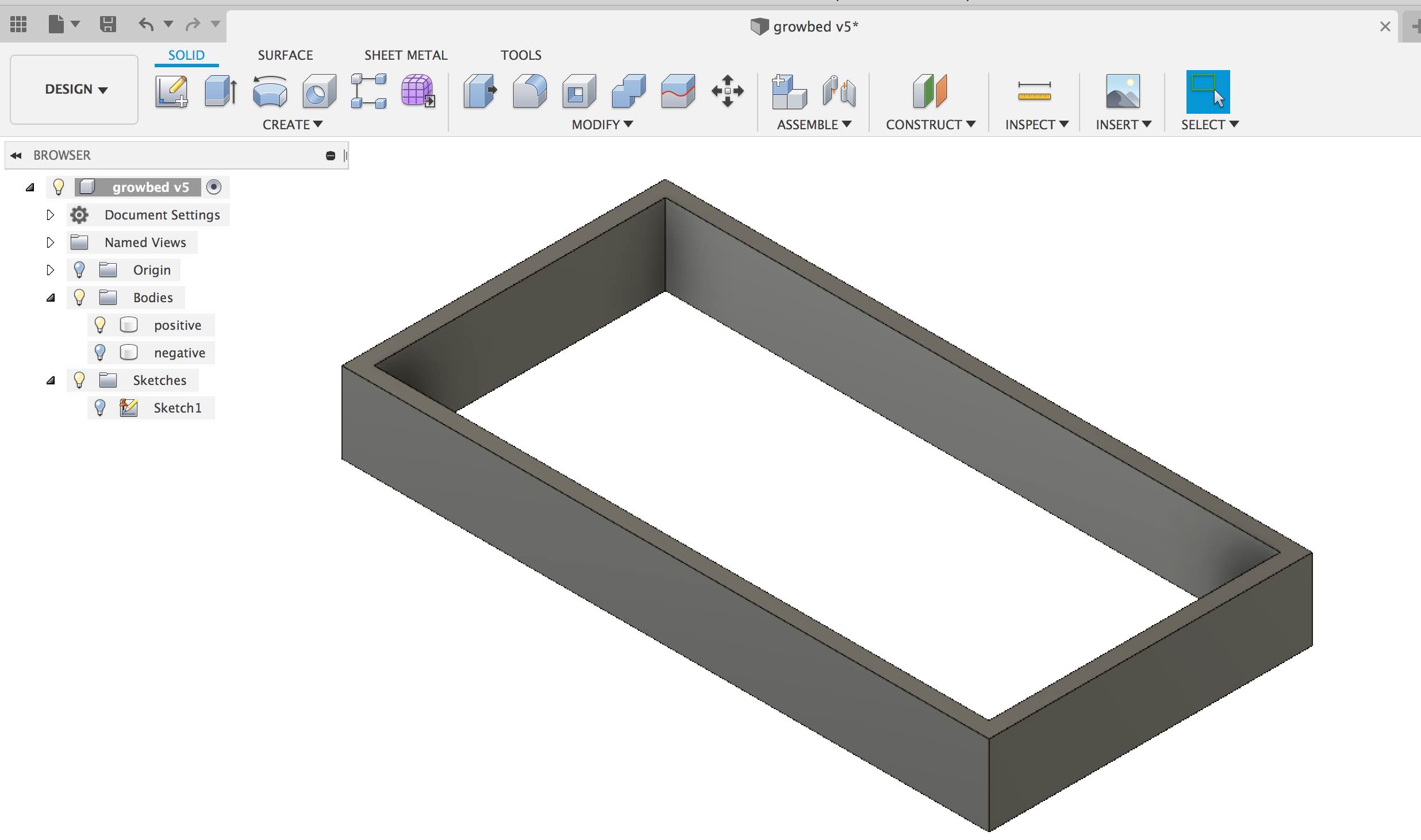
I used fusion to design both positive and negative as i wanted to use the same approach that we used in Molding and Casting week
Steps i followed
- Create a sketch with a two point rectangle with 100 mm * 200 mm width and length (reason is my food computer dimension are 250 mm * 250 mm)
- Create another rectangle which is inside earlier rectangle but apart 5 mm (this is the thickness of my grow bed)
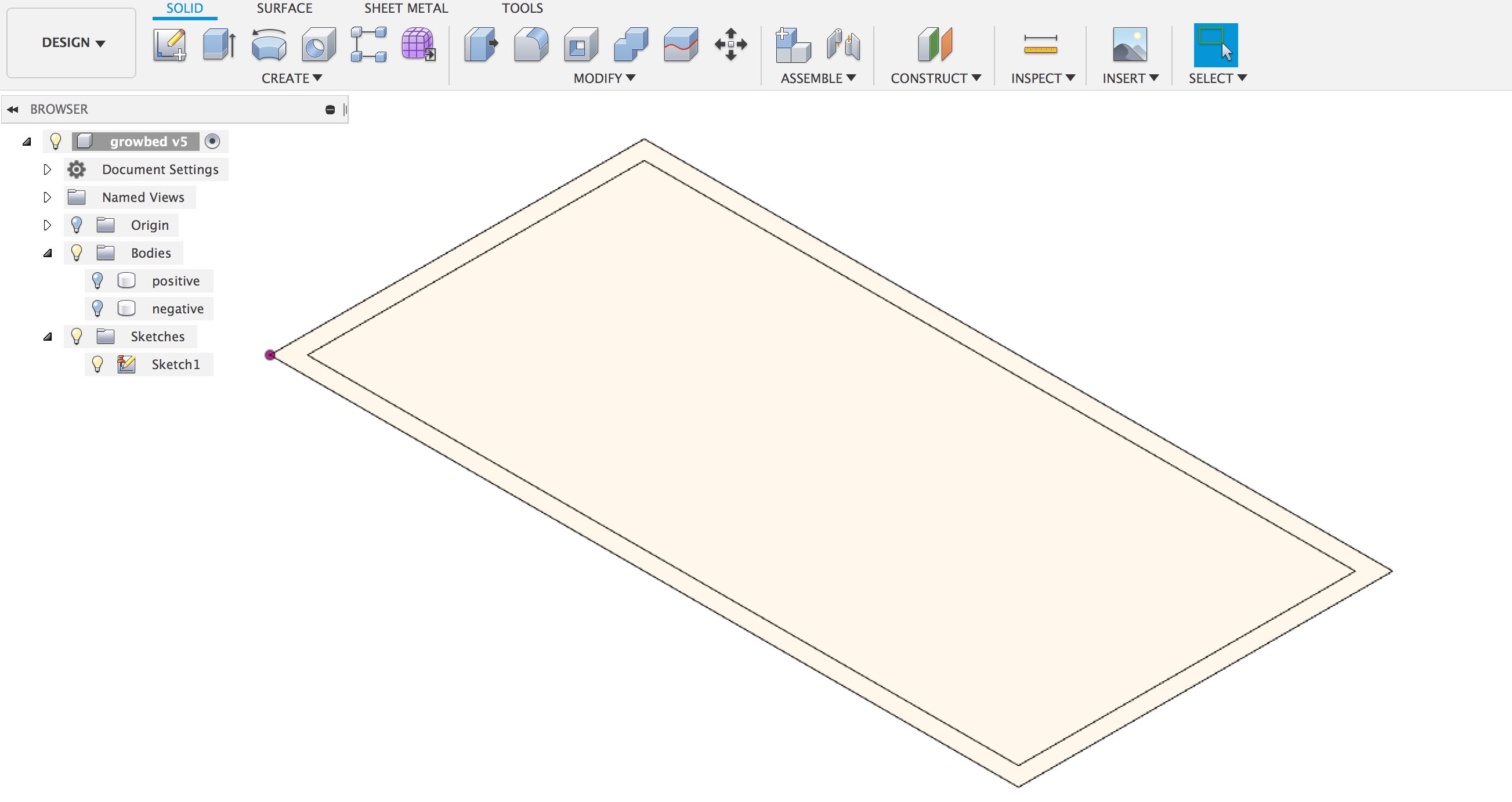
- Extrude the outer rectangle as 25 mm (as material i have was 30 mm thick i want a 5mm thick growbed)
- Save the STL file this is positive of my design
- Follow similar step using extrude to inner redtangle this time 20 mm and then external rectangle as 10 mm (counting as 30 mm of my material thickness)
- Save as STL this is negative of my mold design
- Add fillets 5 mm thick
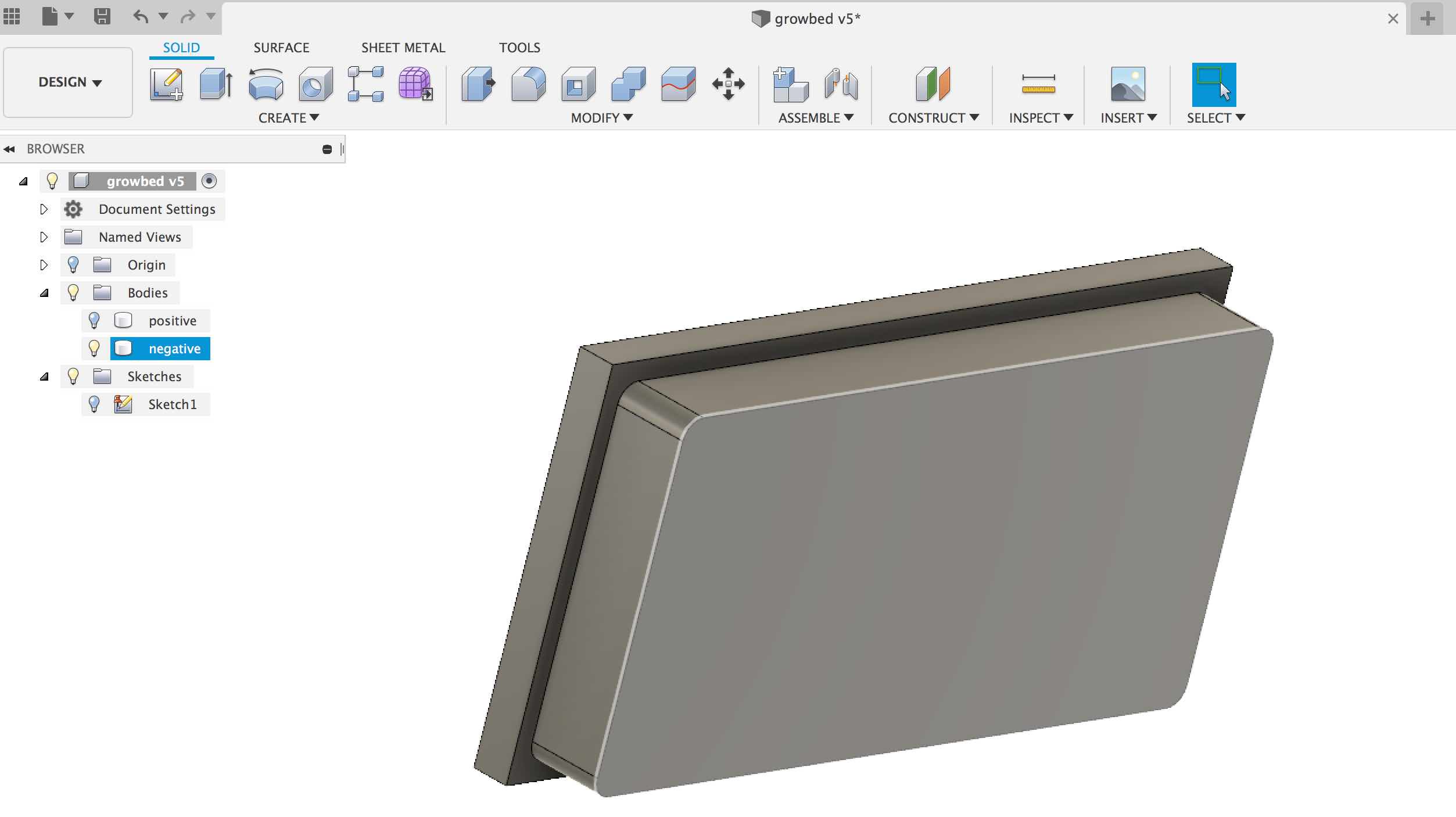
- If you are unclear on steps follow fusion design timelines. But this is what i am trying to get.
Download Files
Toolpath and CNC Milling
Next i created the toolpath using Aspire software. You can learn more on CNC in following week. So i won’t go into details on software in this week but couple of things i tried differently was the Pocket toolpath that helped me create the positive for the mold by using a 6mm end mill.
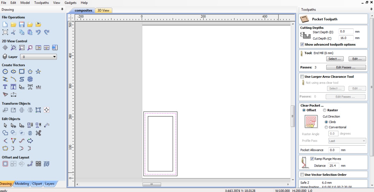
Here is the snapshot after creating a pocket toolpath. It basically replaces all the material.
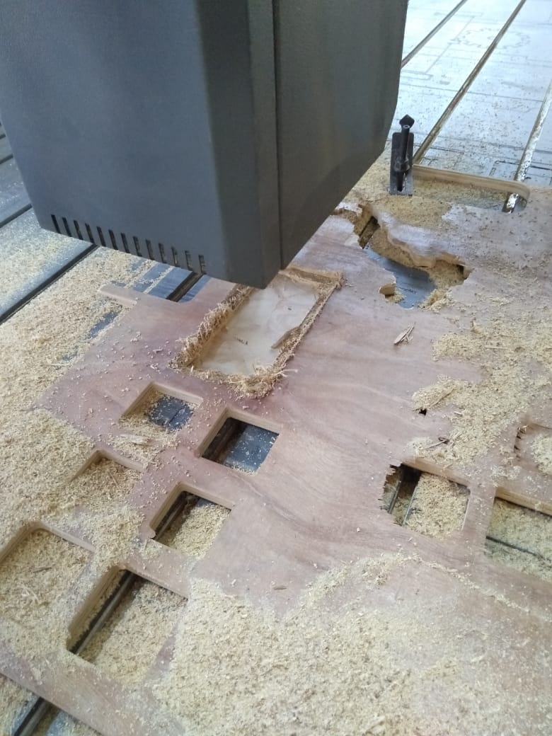
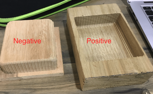
Here are both my parts after doing milling on CNC
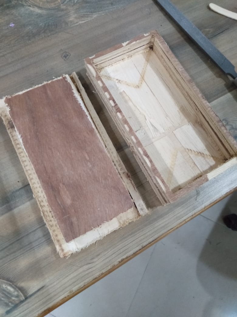
Composites
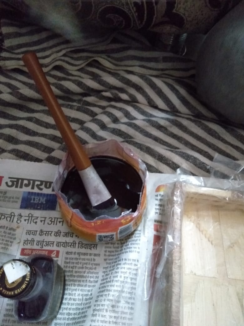
Next was to create the composite.I used the same chemicals, which Narendra from our Lab bought for his assignment use. All resins whether for casting or laminating, require the addition of catalyst (hardener) and accelerator if the resin is not pre-accelerated, to initiate the curing process
These were the list of material
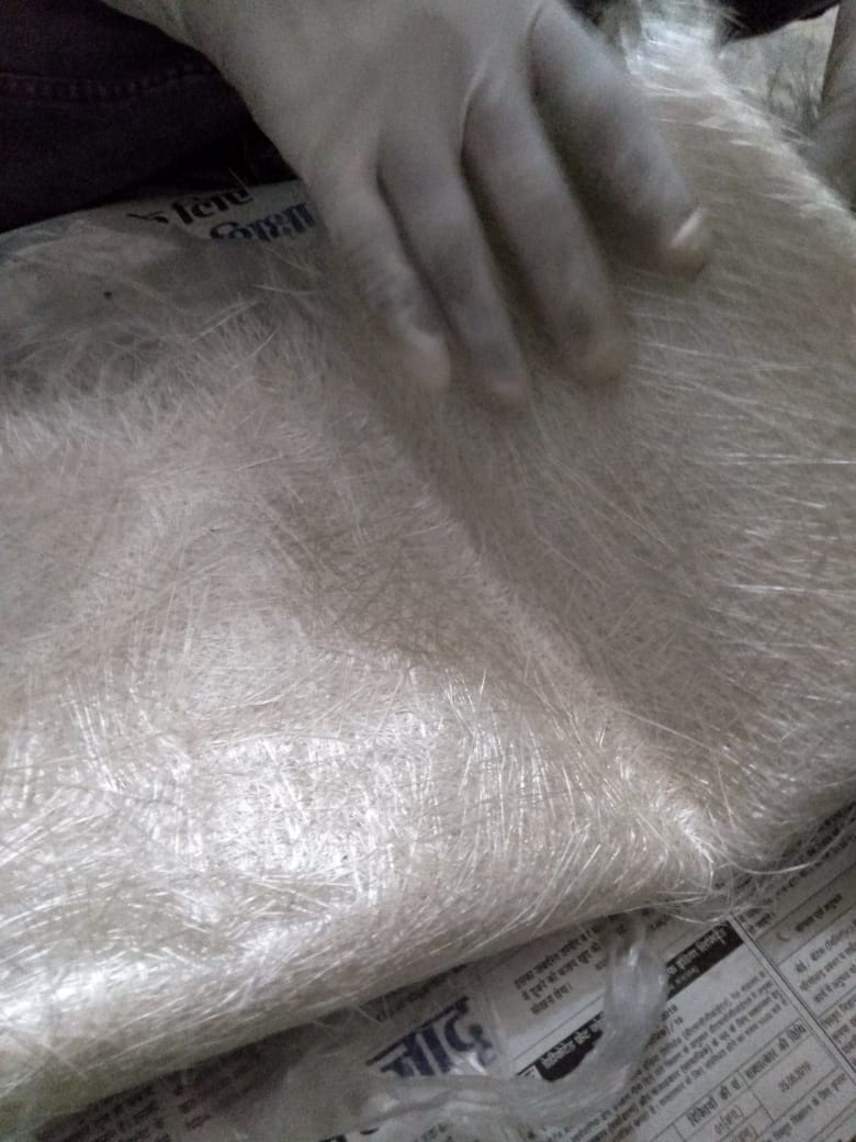
- Glass fibers
- Polyester resin
- Accelerator (Cobalt Naphthenate)
- Hardener(MethylEthyl ketone benzoyl peroxide)

Also i really liked his idea to create a composite by just using positive mold. Though at one point i felt like below and asked myself why i spent so much time creating a positive and negative molds which could have been just simple Pocket toolpath on CNC machine, the week could have been a quick win and i spent almost two weeks getting it done. Anyways but i learnt from these mistakes.

Steps i performed to get the composites done.
-
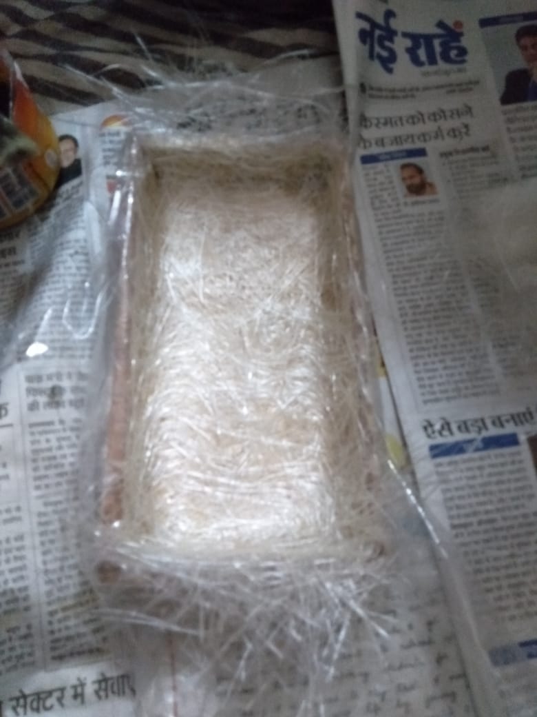
First i wrapped the plastic sheet on my positive mold
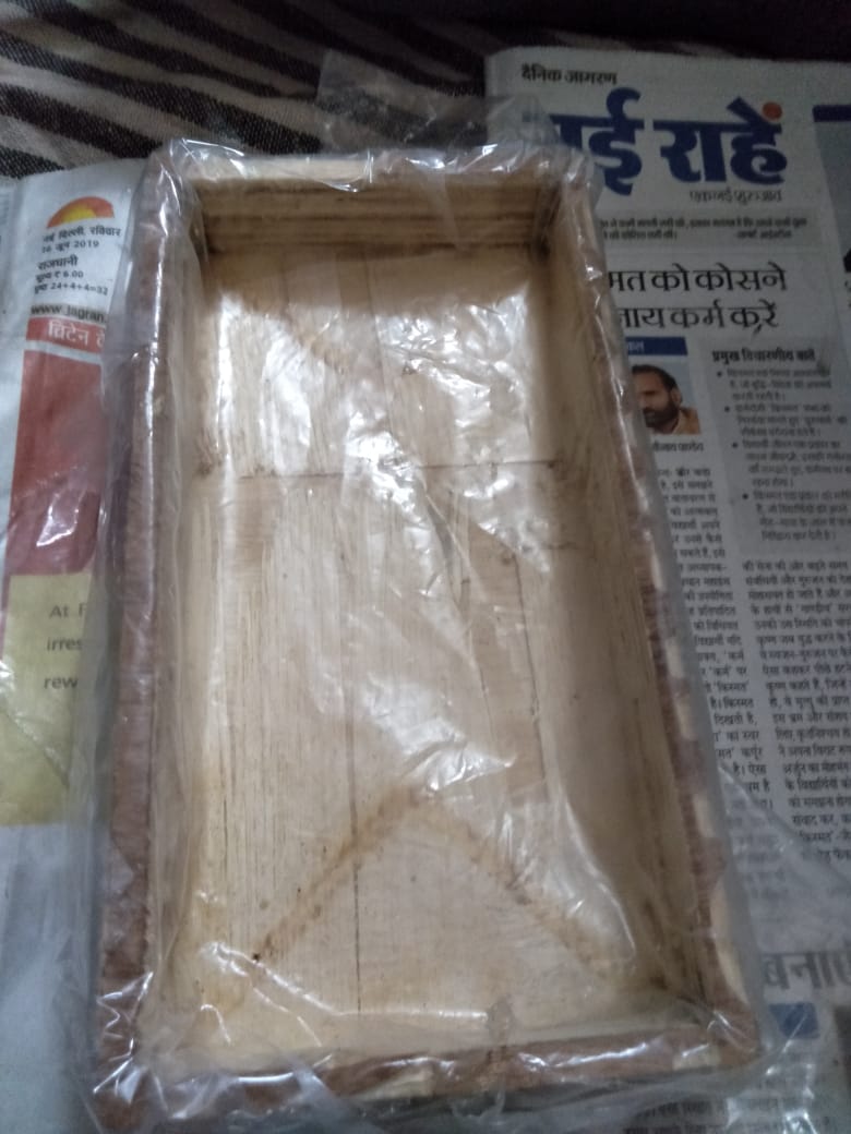
-
Then i prepared the Resin. I took 200gms of the polyester resin and added 2ml of the accelerator to it as the mixing ratio was 100:1
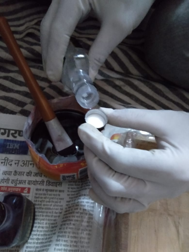
-
Next step was to coat it on inside of plastic sheet and then put fibreglass and repeat the process.Super easy.
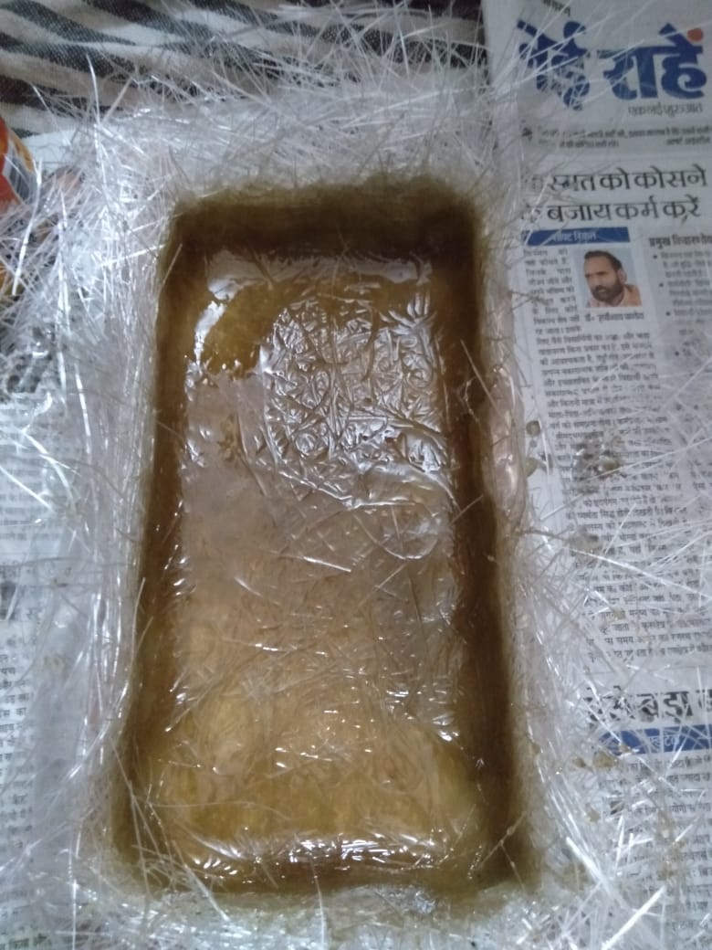
-
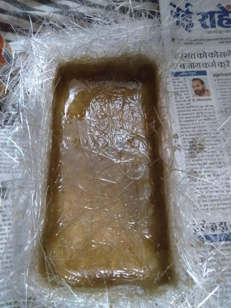
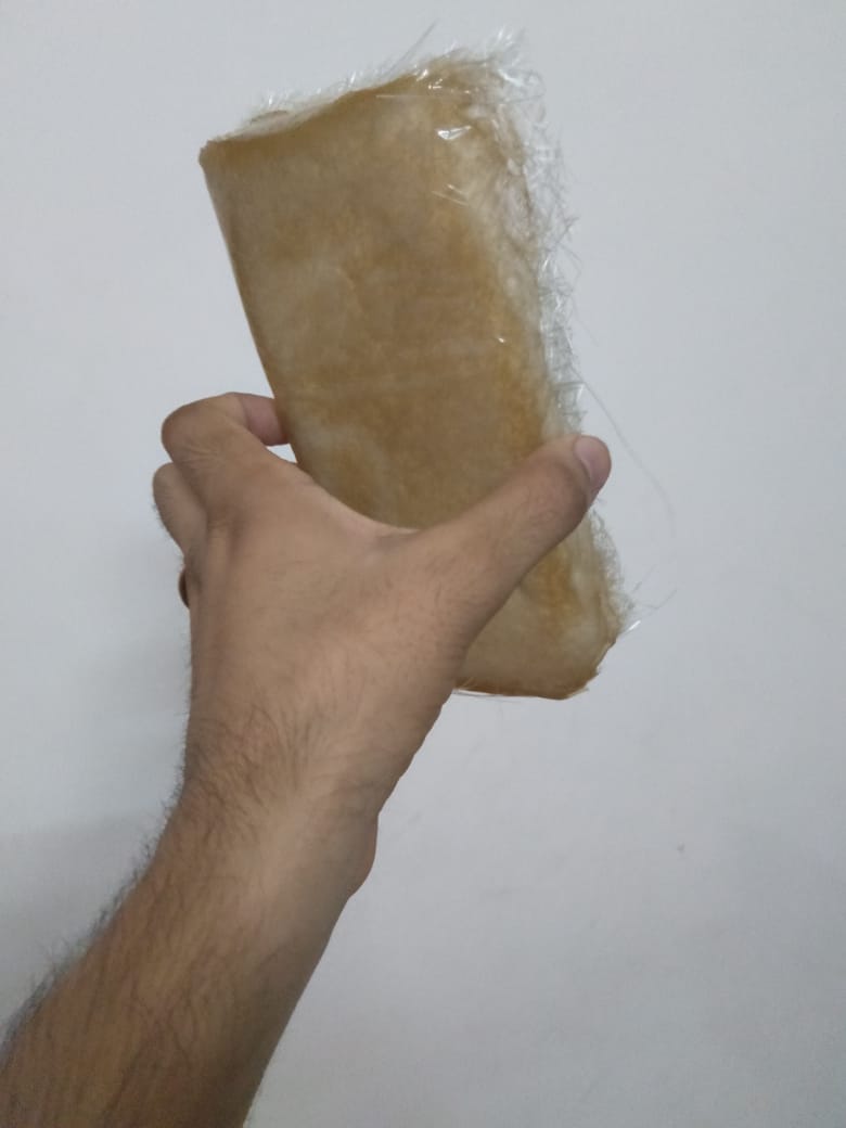
Left the box for 24 hours and then i took out the mold. Here are some snapshots
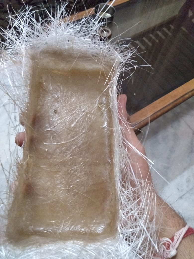
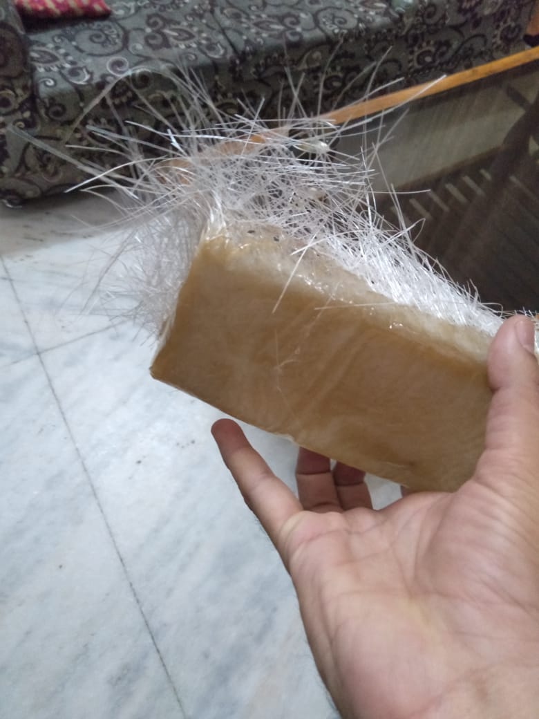
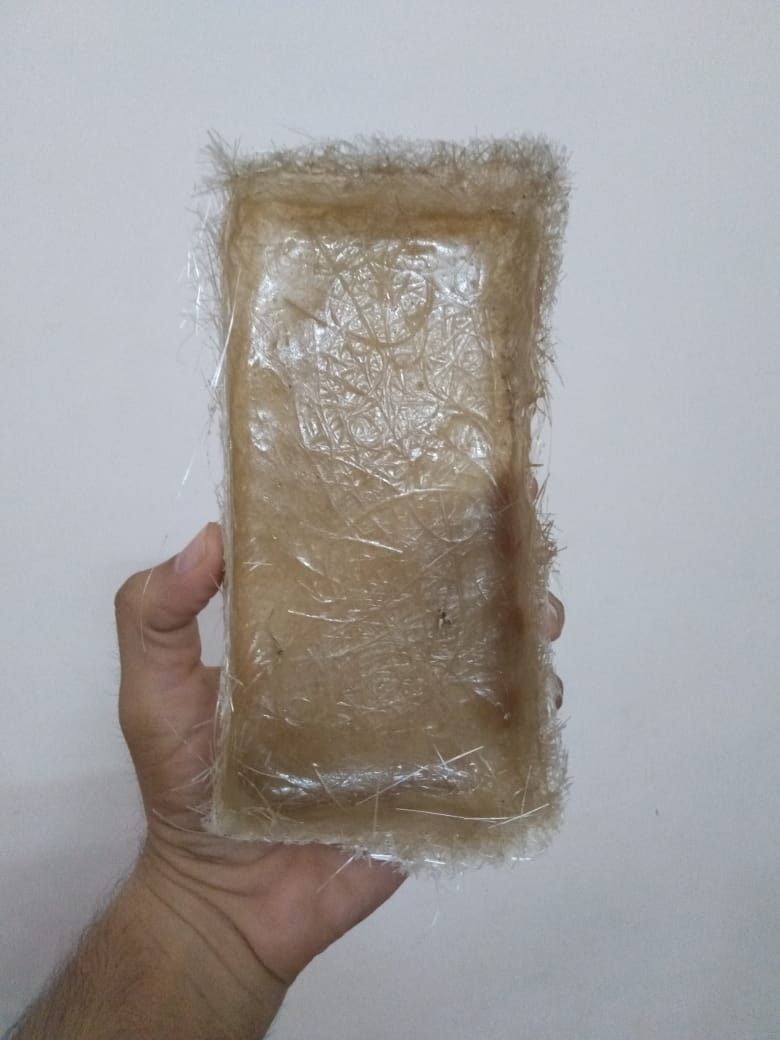
-
Then i cut extra fibre with a scissor and below are some hero snapshot
Overall Learning
- A bit of hectic week as i was not clear on objective
- I have done lot of rework this week, which could have been a simple and easy week turned out to be longest for me
- I learnt about robotics this week and also composites