8. Computer controlled machining
-
The task for this week was to make something big using the computer controlled machining process with the help of wood as the material. Our group assignment was to test runout, alignment, speeds, feeds, and toolpaths for the machine.
-
My goal was to get the parametric modeling right so as to test an cut the same parametric model using laser cut first and then moving on to the shopbot machine to make something big out of it.
-
The group assignment was to test runout, Alignment, Speeds, Feeds and tool paths for our machine.
Group Assignment
We started with group assignment and as discussed with our instructor we performed runout, Alignment, Speeds, Feeds and tool paths for our machine. You can find more details on our Lab Group page. Some of the learnings i had within this group week.
Spindle and feed speed
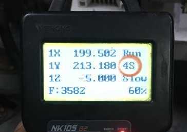
Feed speed is the rate at which the workpiece moves into the cutter. It is always determined in relation to the spindle speed. Using the wrong feed speed can produce too much dust or burn the workpiece. To determine the optimum feed speed you can use a feed speed table or calculate it mathematically.The CNC we had at our facility was an assembled one, Most of it is imported from china, the bed size is about 8X4 Feet. The feed rate and the spindle speed is controlled by Teach pendant in this machine unlike other ones, in which the feed and spindle speed is given in CAM Software.
The spindle speeds in the machine is denoted by a number followed by S. They are 4S, 5S, 6S, 7S. 4S being the slowest and 7S the fastest.Tha maximum spindled speed at 100% is 3200RPM.
Cutting speed
Cutting speed is defined as the speed (usually in feet per minute) of a tool when it is cutting the work. The cutting speed in this machine is mentioned in percentage 10% to 100%, My instructor has asked me not to go beyond 70% due to safety reasons.

Process Involved
The process involves creating a CAD(Computer Aided Design) file of the desired object. Then a specialized CAM (computer-aided Manufacturing) software is required to convert the 3D CAD file into a set of codes which the machines can understand. CNC machining language, called G-code essentially controls all features like feed rate, coordination, location, and speeds. With CNC machining, the computer can control exact positioning and velocity.
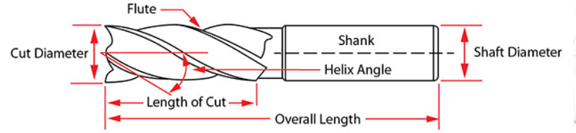
Understanding Bits
CNC routers need bits. They determine the kind of carving you can do, the resolution of your finished designs, and how fast you can move through the material. They come with cutting edges that pull up or push down (sometimes both), they have square or shaped ends, they are made for speed or accuracy, and they come in diameters from a pinpoint to over two inches for standard CNC routing. Milling is done using a cylindrical milling tool mounted in a milling tool holder that is then mounted in the tool spindle on the machine. Mostly the drill bits are made of Carbide Steel or HSS(High Speed Steel).
Procedure to Follow for milling
1) Make a 2d Drawing of the design
- Consider tolerance
- Put the drawing in layers as per the cutting scheme
- Arrange pieces to minimize material wastage
- Leave ample distance between pieces to avoid overlap
2) Export it in .dxf format
Import it into Aspire software to creates tool path - Choose the type of output(cutting, pocketing etc)
- Choose the orientation of the bit
- Check all parameter
- See the preview in 3D
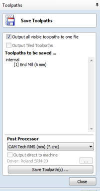
3) Export it as .GCODE
4) Milling machine -Mount the correct drill bit
- Turn on the machine
- Turn on the exhaust
- Rotate spindle if not used for more than 12hrs to ensure flow
5) Plug In the USB Flash Drive
In my case for SIL Router else in Shop Bit U need to import G-Codes
6) Set x,y,z zero(Origin)
- Do Homing
- Start Milling
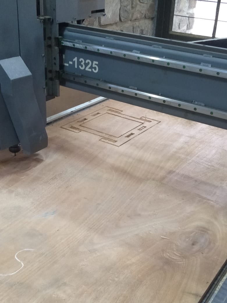
Understanding CNC Machine
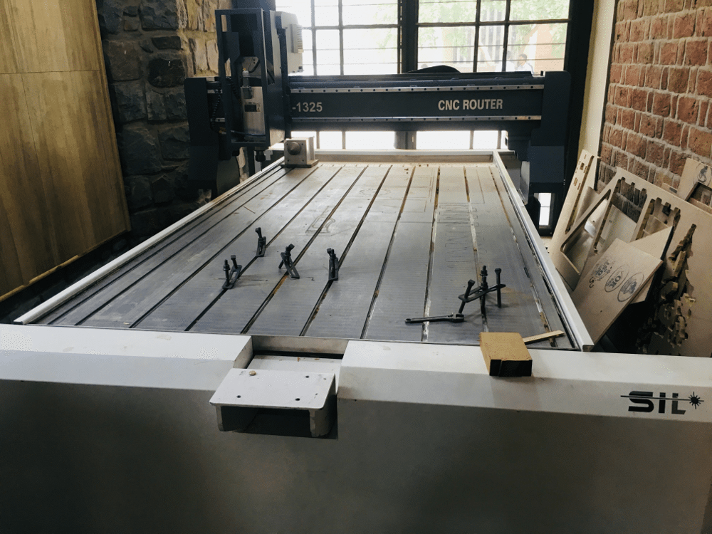
The CNC we had at our facility was an assembled one, Most of it is imported from china. The bed size is about 8X4 Feet. The feed rate and the spindle speed is controlled by Teach pendant in this machine unlike other ones, in which the feed and spindle speed is given in CAM Software.
Machine Bed
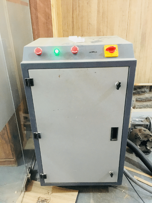
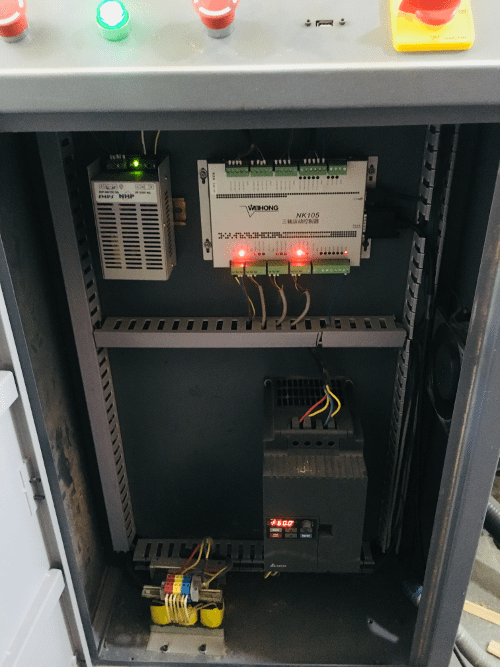
Machine Controller Box
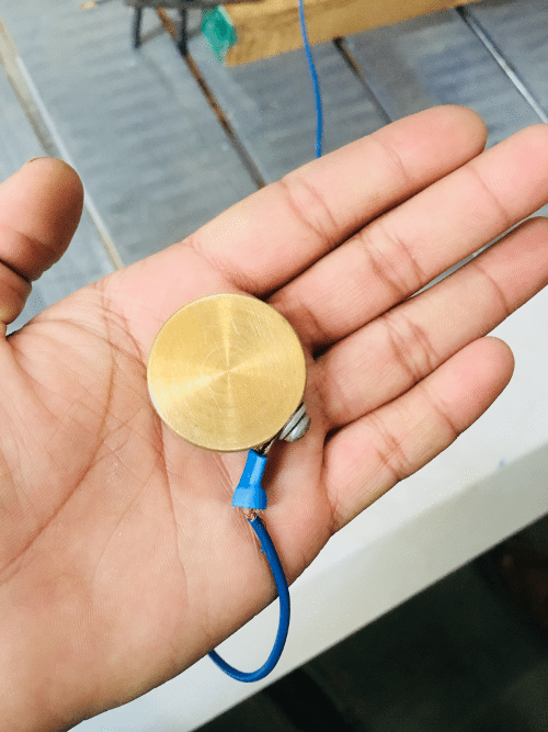
Initialization Tool
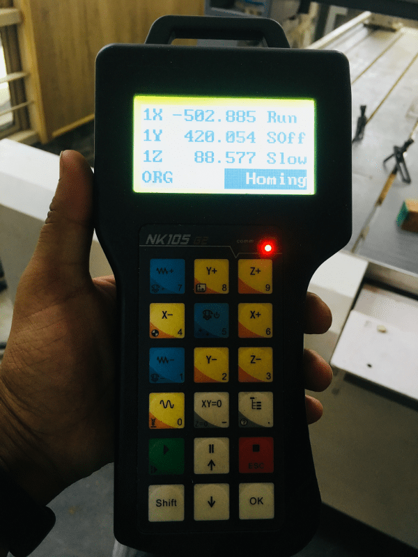
Teach Pendant
CNC Operation
Homing Position
Set X&Y Axis
Set Z axis
Cut Operation
Personal Assignment Design Autodesk Fusion
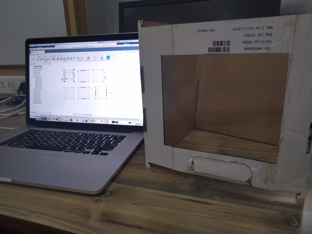
The first objective was to design something on CAD software which i learnt in Week 4. I used autodesk fusion for the design.
Idea
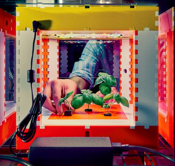
This week i also started looking on building something for my project.
As my project i am working on designing a food computer i wanted to make a big box. I also wanted to test it out on laser cutter before trying the actual design on CNC machine.
Overall objective of design was that it was suppose to be parametric.
Design
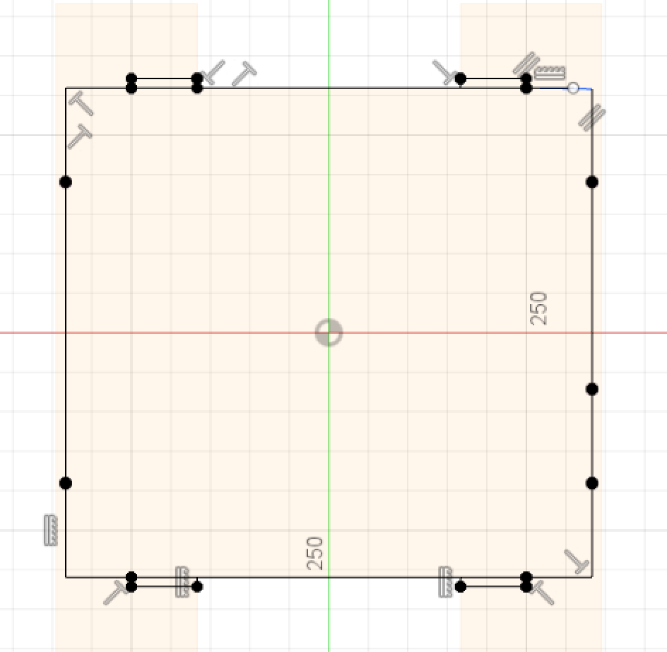
I started with creating different sketches for Front, Back, Left, Right , Top and Bottom for my box. I wanted to make it press fit also.
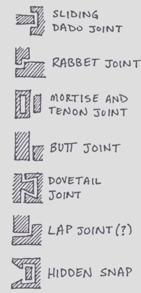
My instructor Rahul shared thar i cannot simply use design files already available in MIT open agriculture github repo but i need to showcase that i can design in CAD software. So instead of using the design from MIT i created a new parametric one. I used mortise tenon and sliding dado joint to build this.
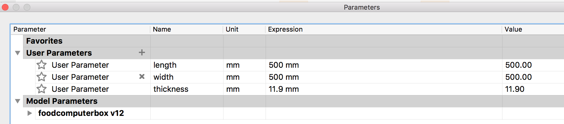
Parameters For Parametric Design
Front and Back Design (Mortise Tenon Join)
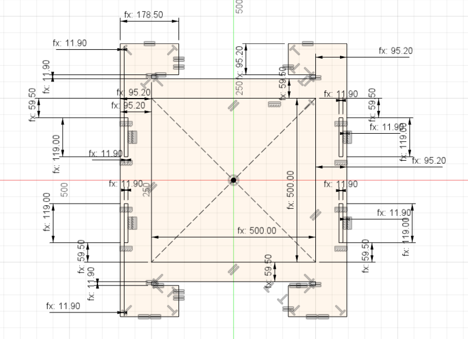
Left and Right Design (Mortise Tenon Join)
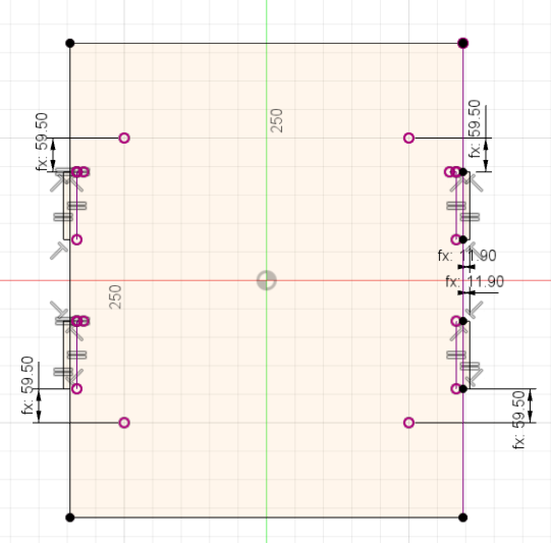
Top and Bottom Design (Sliding Dado Join)
Saving DXF File
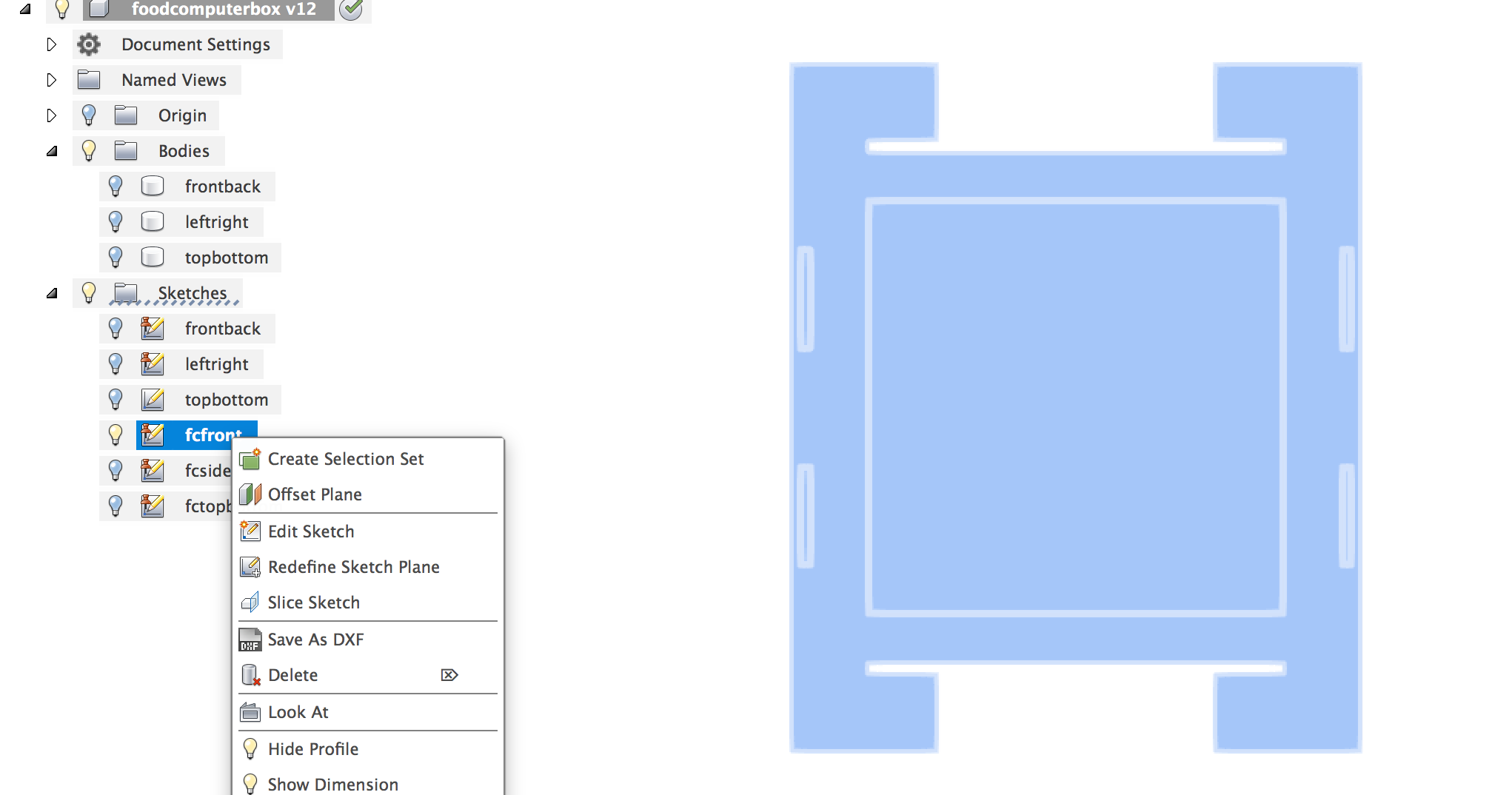
Download all files
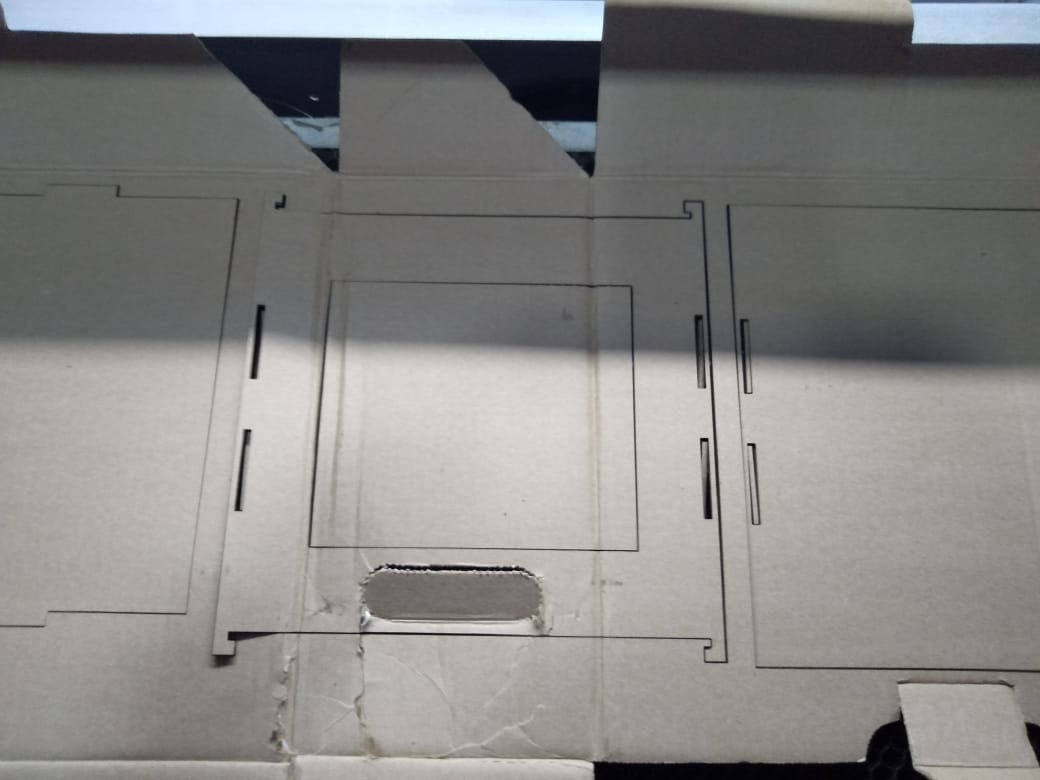
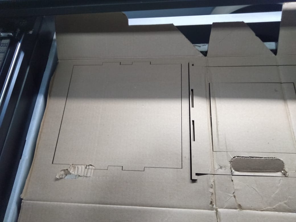
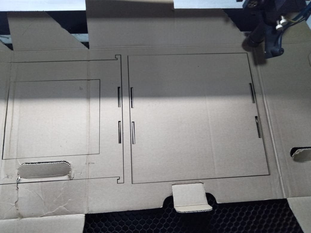
Testing Design on Laser Cutter
Preparing Design File for CNC Machine
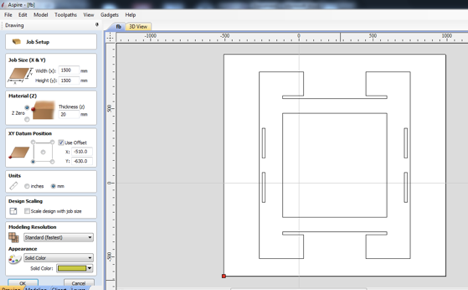
I used Aspire software to create CNC toolpath.
Importing the DXF file and selecting the material thickness
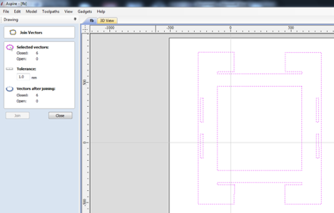
Checking Closed Vectors
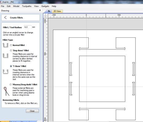
Create Fillets
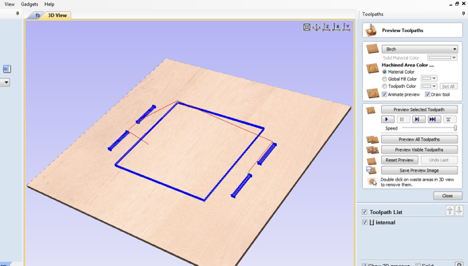
Creating Toolpath

Cutting Operation
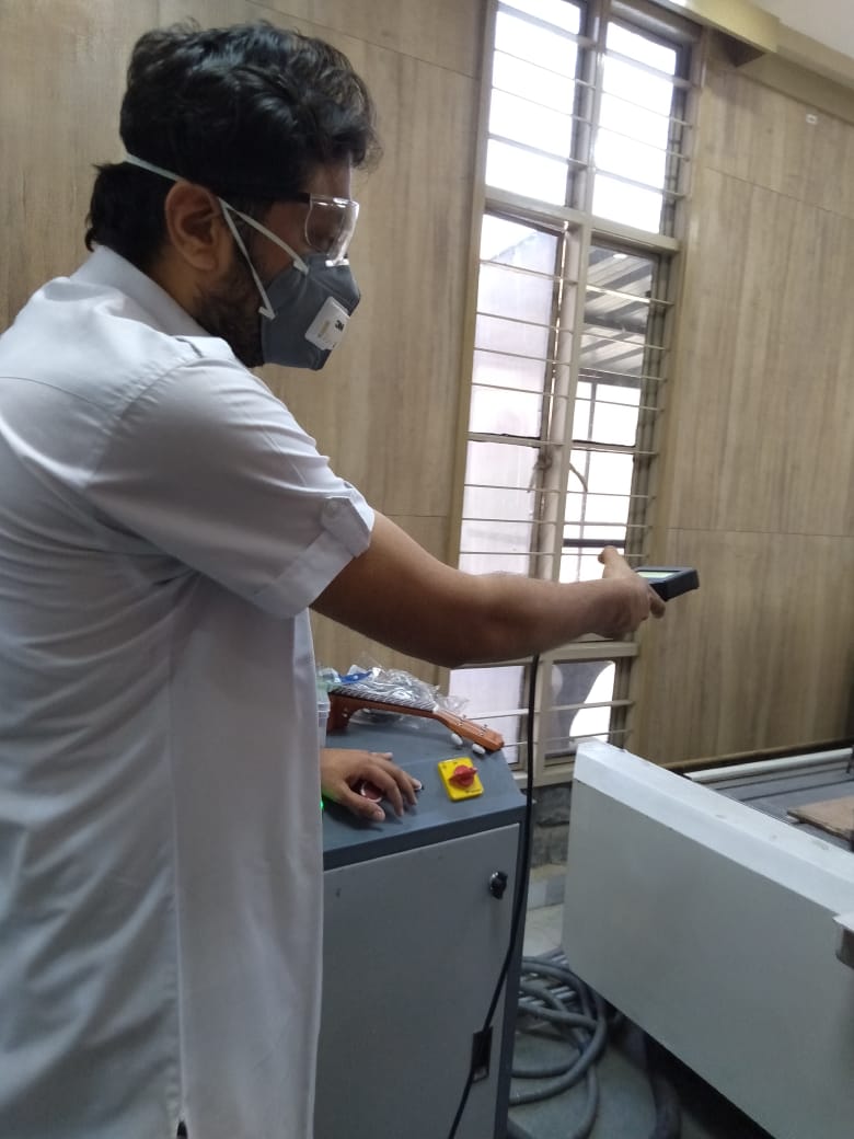
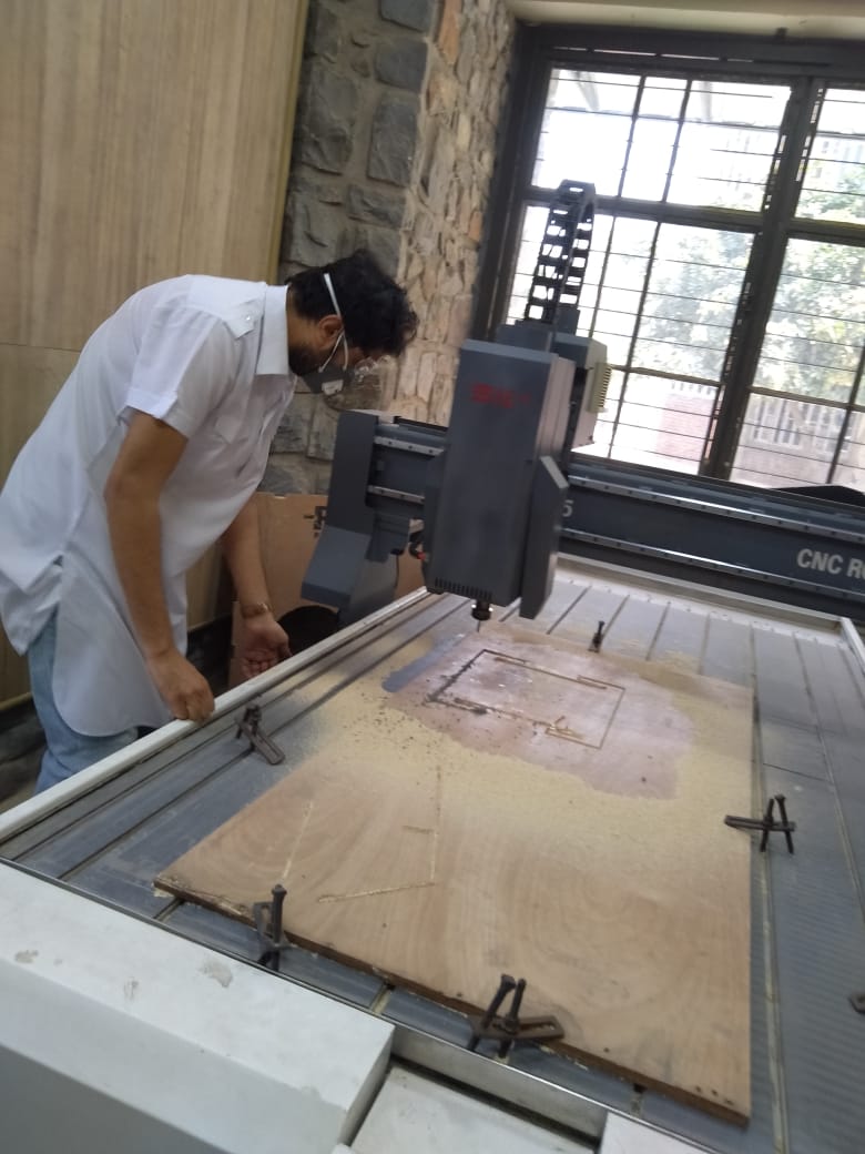
Now there is something we need to keep in mind. Safety is paramount in operating CNC machine. So i dressed up with cool glasses and Mask.

Using teach Pandent to operate the machine
Cutting the front panel for food computer
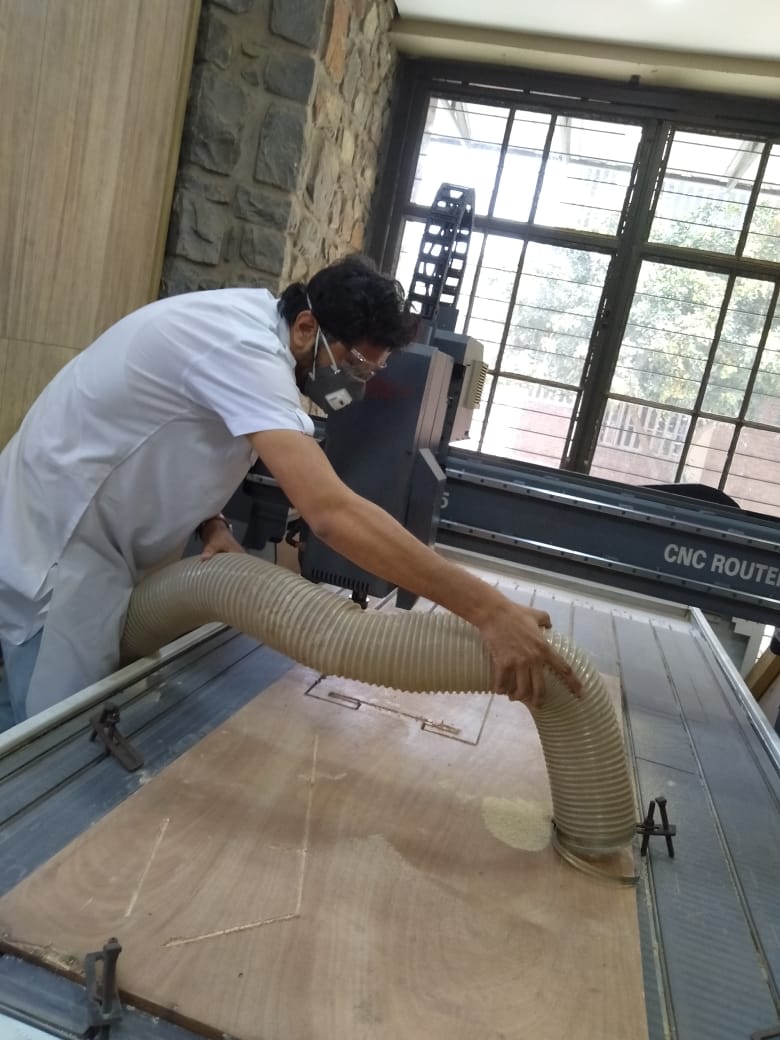
Cleaning using vaccum pump and dust collector system
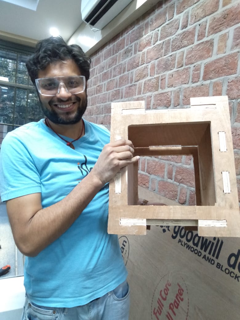
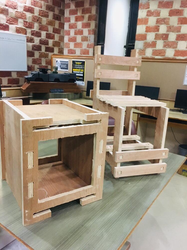
Final Product
It does look cool and came out nice. What was interesting is how the pieces fitted together perfectly.
Some more fun in background
Well it took couple of weeks getting CNC machine fixed at AKGEC. But finally we can sing or “How to Play Almost Nothing”. Rahul our instructor is also quite good in playing various instruments and was generous enough to teach me some basics. Other than learing CNC this week i also had first sesion on playing ukulele instrument.
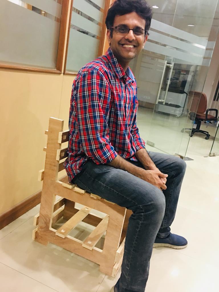
Jai sir with his chair
Key issues i faced and how i resolved it
- The only challenge i faced was unavailability of right size of material in lab. Once i was done with design, was happy with toolpath when i started cutting it on CNC i realised that i don’t had the same length material available. As my design was parametric i was able to scale it down, but before you start cutting on CNC make sure you have right material available in lab.
Overall Learning Outcome
- Its amazing what we can build on CNC machine
- Safety is very important to operate the machine
- You can even learn by sound of machine whether its working fine like Spindle speed you can just see if its cutting properly or machine is taking a load
- It will definetly help me after fab lab as the scale i wanted to achieve for food computer i need to build it to a shipping container level. But for now a Proof of concept parametric design is ready so i will be using it to build much bigger items in future