14. Networking and communications
- The goal for this week’s individual assignment was: design and build a wired &/or wireless network connecting at least two processors
-
group assignment: send a message between two projects
-
I am also planning to connect at least two of the boards with micro controllers on board with the help of I2C Protocol by following the steps provided by Neil.
-
I would also like to try the wireless communication using ESP8266 for my final project
Research
In week9 i already started looking into what i need for final project and you can find out more details on checking out these pages.
In Input Week and Output Week i already tested out sensors for my final project.
Next question i had was that i wanted to control various LED lights, water pump with Alexa and my final board.

So i discussed with my instructor Rahul and asked what should i target in networking week for this. He mentioned that to control these devices by the board i need to use Node MCU ESP8266 chip and also Relays to control the AC/DC devices.
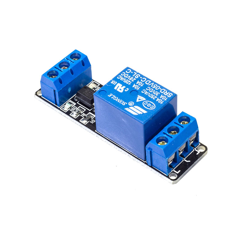

For that i started looking into various tutorial for ESP8266, Relays and alexa and i found following video tutorial quite useful. As i am planning to use satsha kit based board which is compatible with Arduino its easier for me to quickly test out this using breadboard and Arduino.
Relay Tutorial
NodeMCU ESP8266 Tutorial
Alexa and Relay Tutorial
I2C Protocol
For this week i wanted to test out the I2C protocol as in food computer brain raspberry PI and Arduino uses I2C protocol. I actually tested this out in Input Week. Its a very common protocol that is used to communicate across the boards.
So i followed the below tutorial to understand how I2C works
Key Things to note Down
-
The I2C communication bus is very popular and broadly used by many electronic devices because it can be easily implemented in many electronic designs which require communication between a master and multiple slave devices or even multiple master devices. The easy implementations comes with the fact that only two wires are required for communication between up to almost 128 (112) devices when using 7 bits addressing and up to almost 1024 (1008) devices when using 10 bits addressing.
-
How is it possible, a communication between so many devices with just two wires? Well each device has a preset ID or a unique device address so the master can choose with which devices will be communicating.The two wires, or lines are called Serial Clock (or SCL) and Serial Data (or SDA). The SCL line is the clock signal which synchronize the data transfer between the devices on the I2C bus and it’s generated by the master device. The other line is the SDA line which carries the data.The two lines are “open-drain” which means that pull up resistors needs to be attached to them so that the lines are high because the devices on the I2C bus are active low. Commonly used values for the resistors are from 2K for higher speeds at about 400 kbps, to 10K for lower speed at about 100 kbps.
-
Now that the I was able to understand I2C protocol and confident to code the controllers. I started with making the board files for the master and slave . I went through Labs inventory first to check the availability of the components and then moved furthur to make PCB design
Demo I tried using Arduino and NodeMCU
In Embedded programming week9 i already tested out Arduino IDE so i used the same IDE to program my NodeMCU and Arduino board.
First i Programmed the Arduino for I2C using Wire library
#include <Wire.h>
#include <ArduinoJson.h>

void setup() {
 Wire.begin(8);                /* join i2c bus with address 8 */
 Wire.onReceive(receiveEvent); /* register receive event */
 Serial.begin(115200);           /* start serial for debug */
 pinMode(6, OUTPUT); //Attached relay 1 to Pin 6
 pinMode(7, OUTPUT); //Attached relay 2 to Pin 7
}

void loop() {
 delay(100);
}

void processCall(String command){
      DynamicJsonBuffer jsonBuffer;
      JsonObject& root= jsonBuffer.parseObject(command); // NodeMCU send this in JSON format over I2C

       if (root.success()) {
          int gpio = atoi(root["gpio"]);
          Serial.println(gpio);
          int state = atoi(root["state"]);
          Serial.println(state);

          //set GPIO state
          digitalWrite(gpio, state); // This code line setup the pin high and low
       }
}


// function that executes when data is received from master
void receiveEvent(int howMany) {
  String data="";
 while (0 <Wire.available()) {
    char c = Wire.read();      /* receive byte as a character */
    data += c;

  }
    Serial.println(data);           /* print the request data */
    processCall(data);         /* to newline */
}
Next i Programmed the NodeMCU Chip to Have web server running and send Data on I2C to Arduino
// Load Wi-Fi library
#include <ESP8266WiFi.h>
#include <Wire.h>


// Replace with your network credentials
const char* ssid = "Airtel*****"; // Input your wifi network name
const char* password = "*********"; // Input your wifi password

// Set web server port number to 80
WiFiServer server(80);

// Variable to store the HTTP request
String header;

// Auxiliar variables to store the current output state
String relay1State = "off";
String relay2State = "off";
//String relay3State = "off";
//String relay4State = "off";

// Assign output variables to GPIO pins
//const int relay1 = 5; // GPIO5 D1
//const int relay2 = 4; // GPIO4 D2
//const int relay3 = 0; // GPIO0 D3
//const int relay4 = 2; // GPIO2 D4

void setup() {
  Serial.begin(115200);
  // Initialize the output variables as outputs
  //pinMode(relay1, OUTPUT);
  //pinMode(relay2, OUTPUT);
  //pinMode(relay3, OUTPUT);
  //pinMode(relay4, OUTPUT);
  // Set outputs to HIGH. relay active LOW
  //digitalWrite(relay1, HIGH);
  //digitalWrite(relay2, HIGH);
  //digitalWrite(relay3, HIGH);
  //digitalWrite(relay4, HIGH);

  // Connect to Wi-Fi network with SSID and password
  Serial.print("Connecting to ");
  Serial.println(ssid);
  WiFi.begin(ssid, password);
  while (WiFi.status() != WL_CONNECTED) {
    delay(500);
    Serial.print(".");
  }
  // Print local IP address and start web server
  Serial.println("");
  Serial.println("WiFi connected.");
  Serial.println("IP address: ");
  Serial.println(WiFi.localIP());
  server.begin();
  Wire.begin(D1, D2); /* join i2c bus with SDA=D1 and SCL=D2 of NodeMCU */
}

void loop() {
  WiFiClient client = server.available();   // Listen for incoming clients

  if (client) {                             // If a new client connects,
    Serial.println("New Client.");          // print a message out in the serial port
    String currentLine = "";                // make a String to hold incoming data from the client
    while (client.connected()) {            // loop while the client's connected
      if (client.available()) {             // if there's bytes to read from the client,
        char c = client.read();             // read a byte, then
        Serial.write(c);                    // print it out the serial monitor
        header += c;
        if (c == '\n') {                    // if the byte is a newline character
          // if the current line is blank, you got two newline characters in a row.
          // that's the end of the client HTTP request, so send a response:
          if (currentLine.length() == 0) {
            // HTTP headers always start with a response code (e.g. HTTP/1.1 200 OK)
            // and a content-type so the client knows what's coming, then a blank line:
            client.println("HTTP/1.1 200 OK");
            client.println("Content-type:text/html");
            client.println("Connection: close");
            client.println();

            // turns the GPIOs on and off
            if (header.indexOf("GET /6/on") >= 0)
            {
              Serial.println("GPIO 6 on");
              relay1State = "on";
              //digitalWrite(relay1, LOW);
              Serial.print("Switch 1 turn off ...");
              Wire.beginTransmission(8); /* begin with device address 8 */
              Wire.write("{\"gpio\":6,\"state\":0}");  /* sends hello string */
              Wire.endTransmission();    /* stop transmitting */
            }
            else if (header.indexOf("GET /6/off") >= 0)
            {
              Serial.println("GPIO 6 off");
              relay1State = "off";
              //digitalWrite(relay1, HIGH);
              Serial.print("Switch 1 turn on ...");
              Wire.beginTransmission(8); /* begin with device address 8 */
              Wire.write("{\"gpio\":6,\"state\":1}");  /* sends hello string */
              Wire.endTransmission();    /* stop transmitting */
            }
            else if (header.indexOf("GET /7/on") >= 0) {
              Serial.println("GPIO 7 on");
               relay2State = "on";
                Serial.print("Switch 2 turn off ...");
                Wire.beginTransmission(8); /* begin with device address 8 */
                Wire.write("{\"gpio\":7,\"state\":0}");  /* sends hello string */
                Wire.endTransmission();    /* stop transmitting */
                //digitalWrite(relay2, LOW);
            }
            else if (header.indexOf("GET /7/off") >= 0) {
              Serial.println("GPIO 7 off");
              relay2State = "off";
               Serial.print("Switch 2 turn on ...");
                Wire.beginTransmission(8); /* begin with device address 8 */
                Wire.write("{\"gpio\":7,\"state\":1}");  /* sends hello string */
                Wire.endTransmission();    /* stop transmitting */
              //digitalWrite(relay2, HIGH);
            }
            /*else if (header.indexOf("GET /0/on") >= 0)
            {
              Serial.println("GPIO 0 on");
              relay3State = "on";
              digitalWrite(relay3, LOW);
            }
            else if (header.indexOf("GET /0/off") >= 0)
            {
              Serial.println("GPIO 0 off");
              relay3State = "off";
              digitalWrite(relay3, HIGH);
            }
            else if (header.indexOf("GET /2/on") >= 0) {
              Serial.println("GPIO 2 on");
              relay4State = "on";
              digitalWrite(relay4, LOW);
            }
            else if (header.indexOf("GET /2/off") >= 0) {
              Serial.println("GPIO 2 off");
              relay4State = "off";
              digitalWrite(relay4, HIGH);
            }*/

            // Display the HTML web page
            client.println("<!DOCTYPE html><html>");
            client.println("<head><meta name=\"viewport\" content=\"width=device-width, initial-scale=1\">");
            client.println("<link rel=\"icon\" href=\"data:,\">");
            // CSS to style the on/off buttons
            // Feel free to change the background-color and font-size attributes to fit your preferences
            client.println("<style>html { font-family: Helvetica; display: inline-block; margin: 0px auto; text-align: center;}");
            client.println(".button { background-color: #195B6A; border: none; color: white; padding: 12px 24px;");
            client.println("text-decoration: none; font-size: 20px; margin: 2px; cursor: pointer;}");
            client.println(".button2 {background-color: #77878A;}</style></head>");

            // Web Page Heading
            client.println("<body><h1>NodeMCU Web Server</h1>");

            // Display current state, and ON/OFF buttons for GPIO 6
            client.println("<p>Relay 1 - State " + relay1State + "</p>");
            // If the relay1State is off, it displays the ON button
            if (relay1State == "off") {
              client.println("<p><a href=\"/6/on\"><button class=\"button\">ON</button></a></p>");
            } else {
              client.println("<p><a href=\"/6/off\"><button class=\"button button2\">OFF</button></a></p>");
            }


            // Display current state, and ON/OFF buttons for GPIO 7
            client.println("<p>Relay 2 - State " + relay2State + "</p>");
            // If the relay2State is off, it displays the ON button
            if (relay2State == "off") {
              client.println("<p><a href=\"/7/on\"><button class=\"button\">ON</button></a></p>");
            } else {
              client.println("<p><a href=\"/7/off\"><button class=\"button button2\">OFF</button></a></p>");
            }

            client.println("</body></html>");

            // The HTTP response ends with another blank line
            client.println();
            // Break out of the while loop
            break;
          } else { // if you got a newline, then clear currentLine
            currentLine = "";
          }
        } else if (c != '\r') {  // if you got anything else but a carriage return character,
          currentLine += c;      // add it to the end of the currentLine
        }
      }
    }
    // Clear the header variable
    header = "";
    // Close the connection
    client.stop();
    Serial.println("Client disconnected.");
    Serial.println("");
  }
}
Below is the final demo of how i am able to integrate NodeMCU and Arduino over I2C
Final Project Board Networking Integration
Once comfortable with the I2C and how to control relays i tried same code on my final project board and was able to turn on and off the relays. Please find the video for the same. I already milled the board in Week 11 Input Devices and you can refer that week to get more details on the project board.
Designing the PCB for Personal Assignment
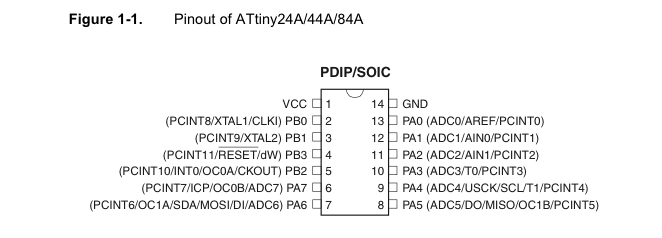
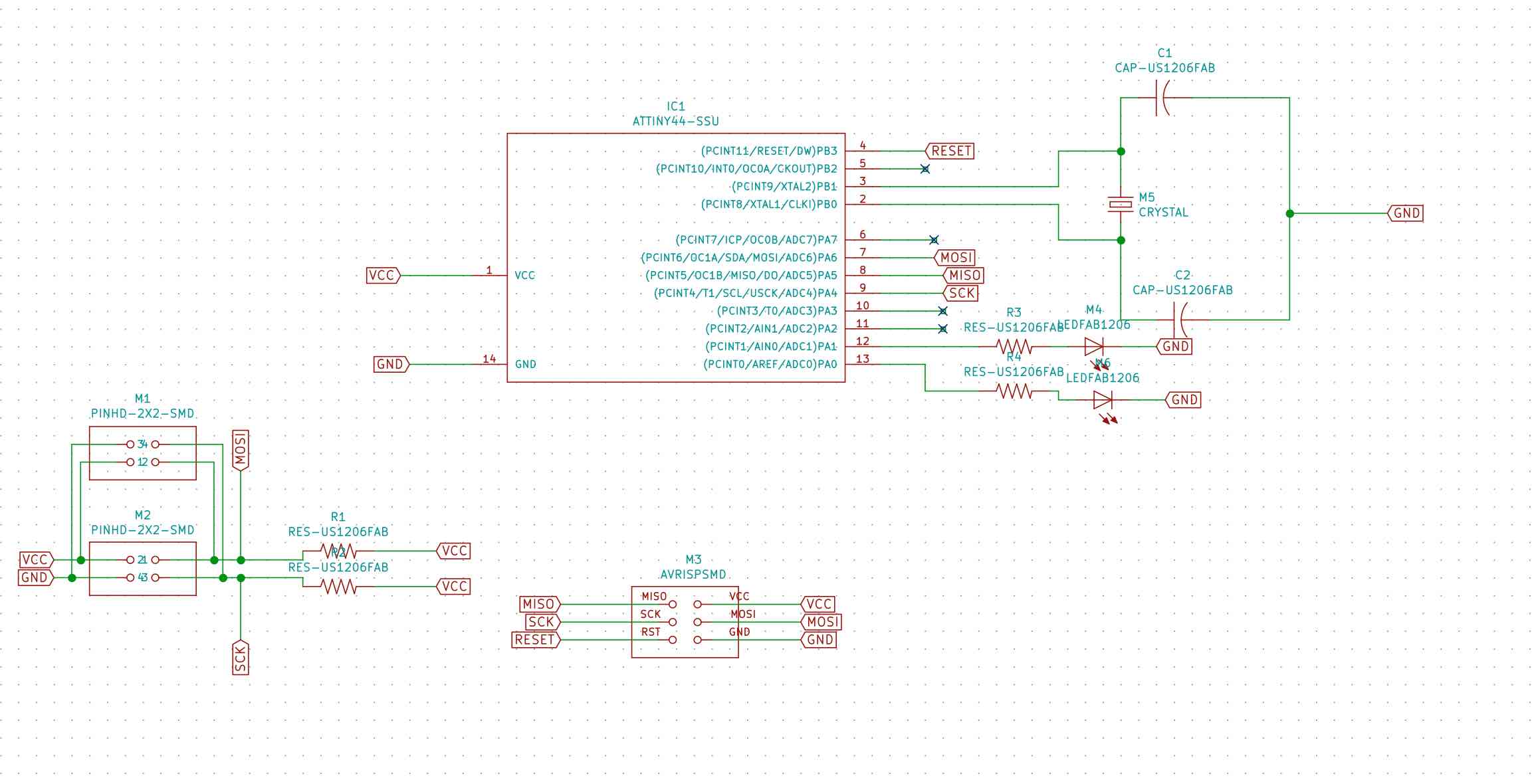
As part of this week we needed to design master and slave board so i decided to use Atttiny 44. From the below diagram it may be noticed that PA6 and PA4 are the SDA (Serial Data) and SCL (Serial Clock), these pins would be furthur considered while designing the PCB.
Now that the I was able to understand I2C protocol and confident to code the controllers I started with making the board files for the master and slave. I went through Labs inventory first to check the availability of the components and then moved furthur to design the PCB.
Designing the master board
I used Kicad as my designing software. The modular approach of the software allows me to give more preference over Eagle.
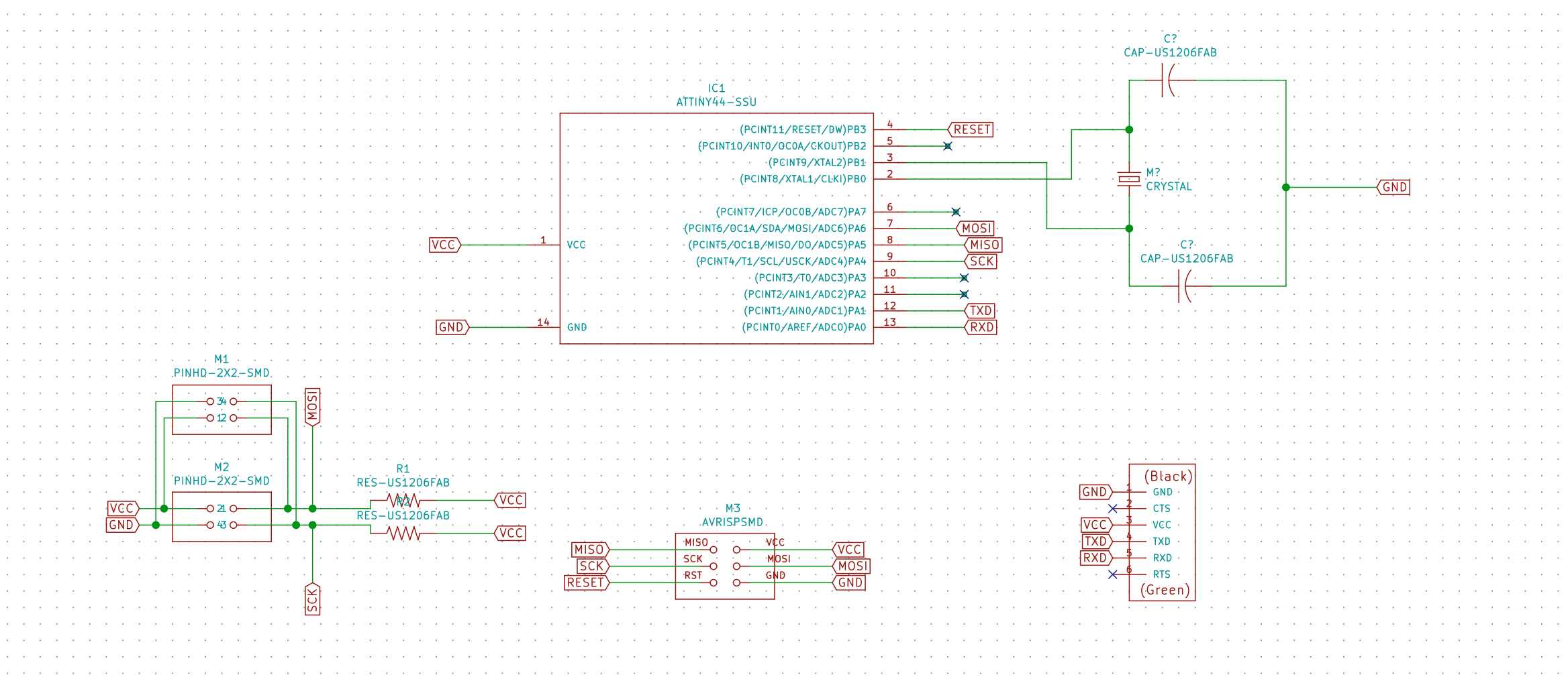
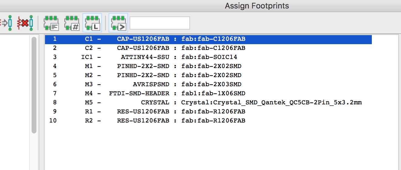
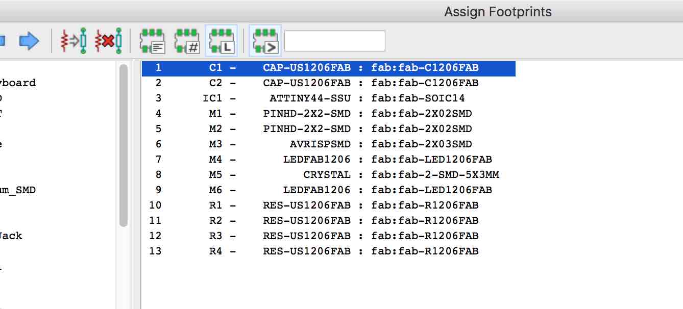
Next i assigned the footprint and generated a netlist for SMD footprint library from Fab modules.
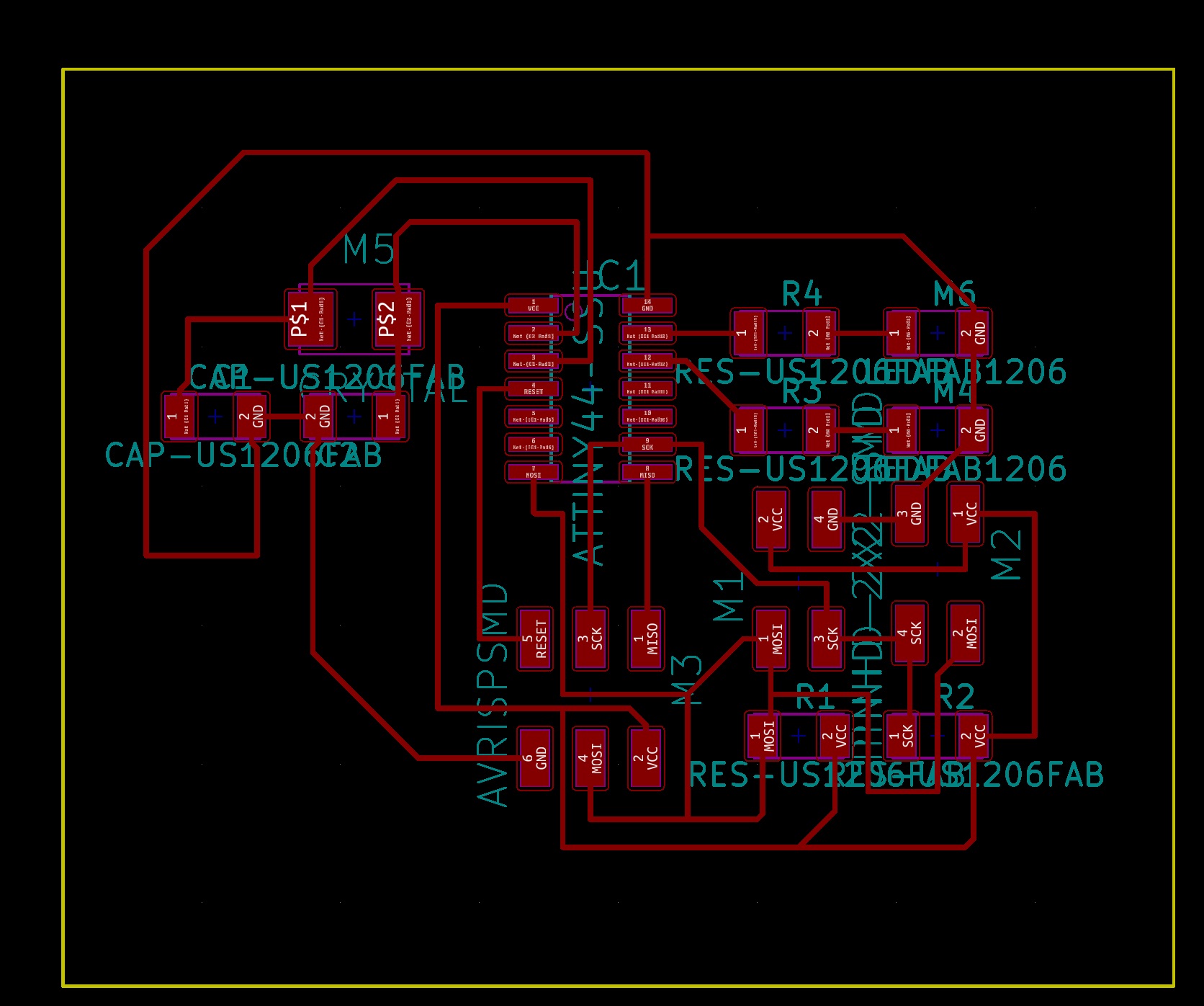
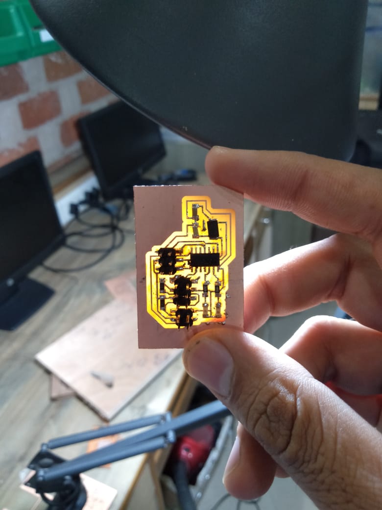
Next step was routing the board
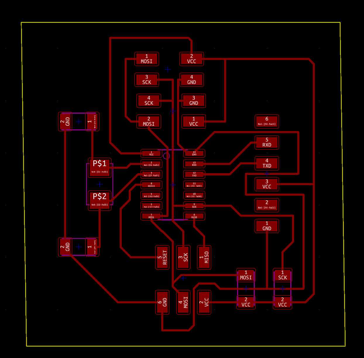
Designing the Slave board
You can download the files from below. I followed the similar approach as i did for master board
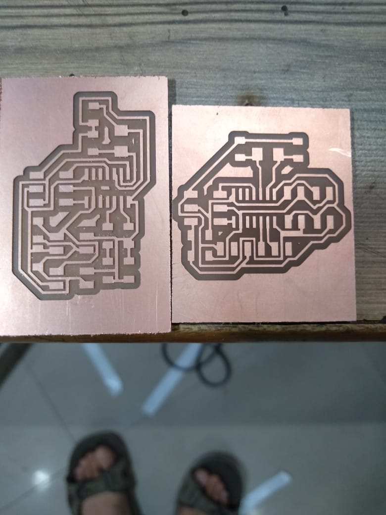
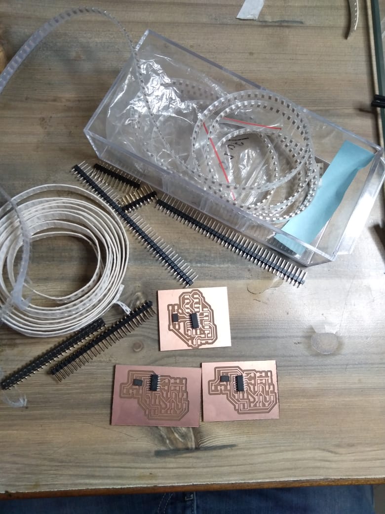
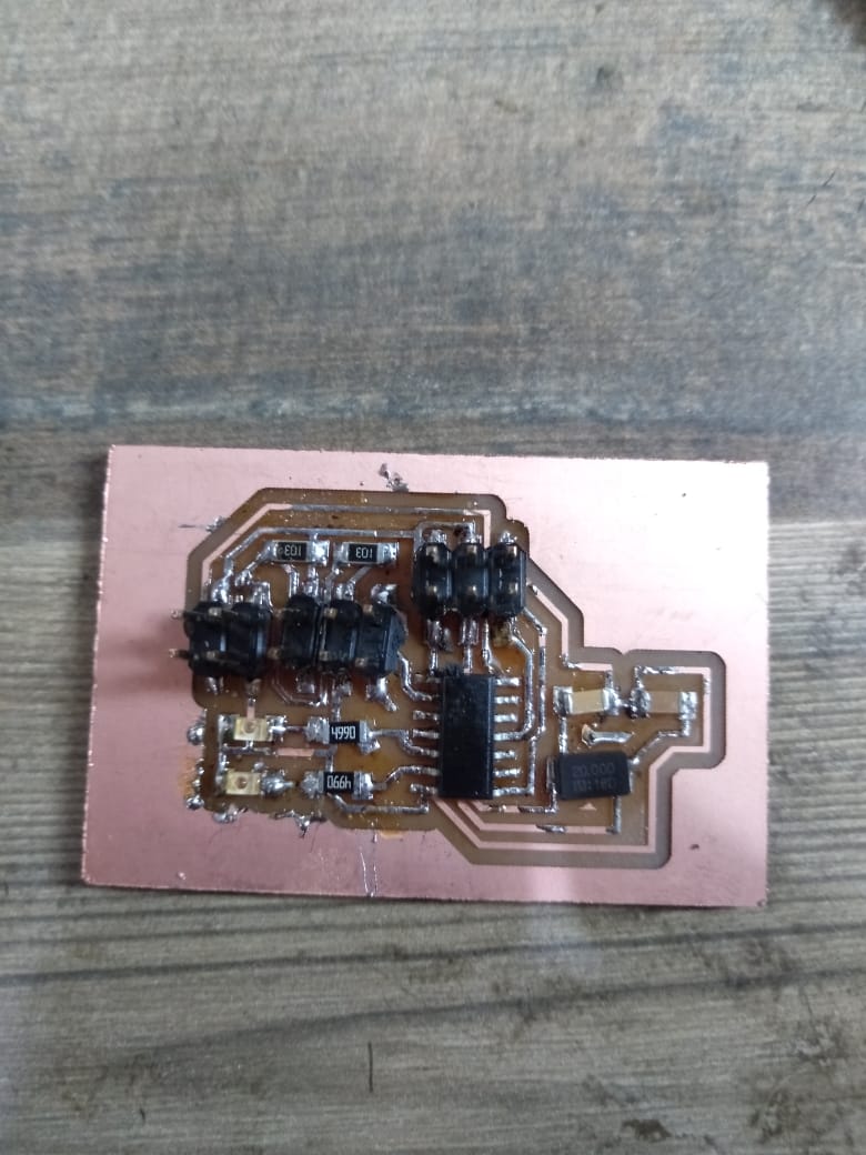
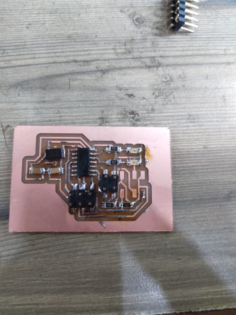
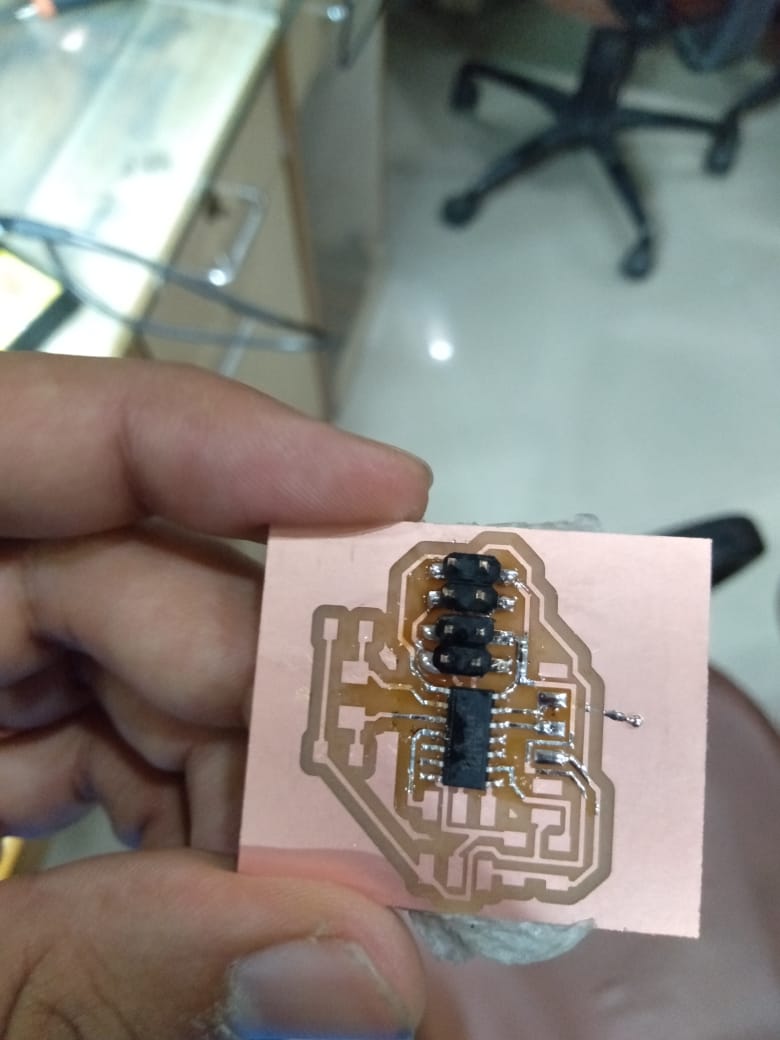
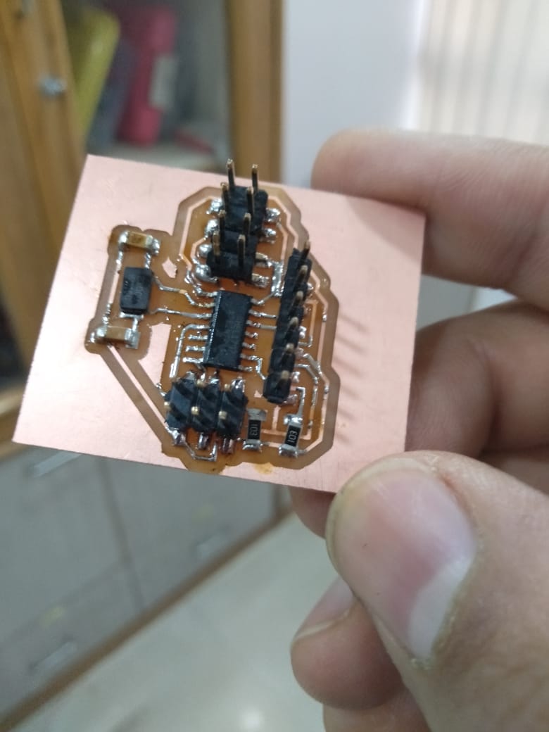
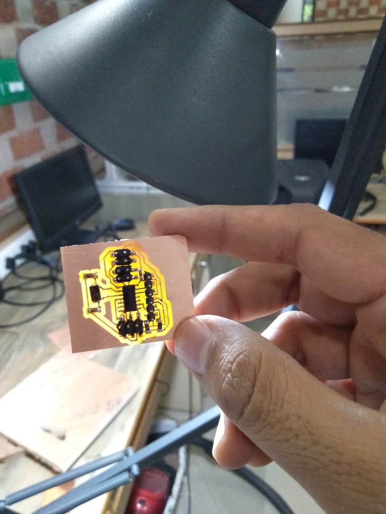
Milling and Soldering The Board
Week5 Electronics Production cover milling and soldering process in detail. So i am not covering the same in this week again. But you can refer the details in week 5 for using SRM and soldering. Here the hero snapshot for the master and slave board after milling and soldering.
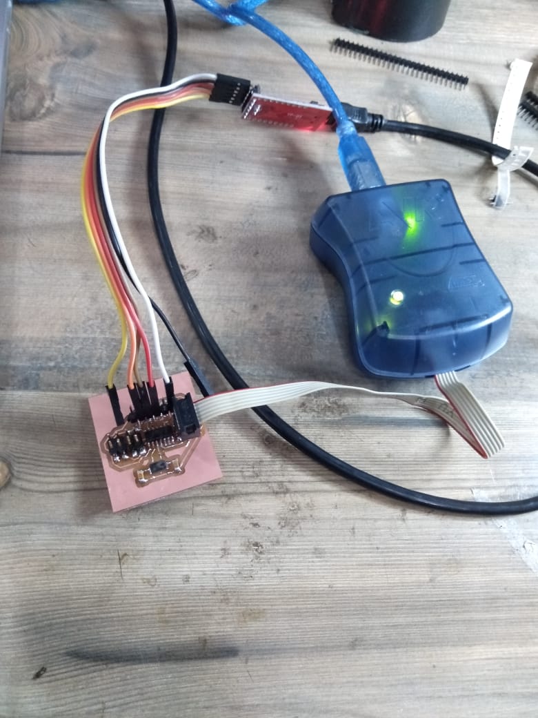
Programming the Board
You can learn more about programming microcontroller in Embedded Programming Week 9 . Again i am using FTDI, AVR programmer and Arduino IDE to program the board.
Below are the steps i used to program the board.
- Attach AVR programmer to the pin headers (AVRISP)
- Provide VCC and GND using FTDI
- Open Arduino select Board and the Processor as Atttiny 44 , Processor and External Clock (20 MhZ)
- Burn bootloader
- Open below sketches and upload the code in master and slave boards
Below is the demo video you can refer that showcase the process
Master Board Code
#include "Wire.h" // This is I2C library
#include "SoftwareSerial.h" // This is used for making rx tx pins using software
#define Rx 0
#define Tx 1
SoftwareSerial myserial(Rx, Tx); // declared Rx and Tx Pins

void setup() {
  Wire.begin(); // I2C communication Started
  myserial.begin(9600); // Serial communiation Started
  myserial.println("Communication Started");
}

void loop() {
  char d; // Character type declaration to store a character.
  if (myserial.available() > 0)
  {
    d = myserial.read(); // Read serial and store its value in variable d.
    if (d == '1') {   // Now transmit data over the I2C lines according to the cases.
      Wire.beginTransmission(1); // Communication started with first node
      Wire.write(1); // Value sent over the channel
      Wire.endTransmission(); // Communication Ended
      myserial.println("send :- ");
      myserial.print(d); // Print on Serial Monitor

    }
    if (d == '2') {             // Same of others.
      Wire.beginTransmission(1);
      Wire.write(2);
      Wire.endTransmission();
      myserial.println("send :- ");
      myserial.print(d);

    }
    if (d == '3') {
      Wire.beginTransmission(2);
      Wire.write(3);
      Wire.endTransmission();
      myserial.println("send :- ");
      myserial.print(d);

    }
    if (d == '4') {
      Wire.beginTransmission(2);
      Wire.write(4);
      Wire.endTransmission();
      myserial.println("send :- ");
      myserial.print(d);

    }

  }
  delay(10); // Delay to make sure whole CPU is not consumed.
}
Slave Board 1 Code
#include "Wire.h" // This is I2C library

int led1 = A0;
int led2 = A1;

void setup() {
  Wire.begin(1); // I2C Communication Started
  Wire.onReceive(receiveEvent); // Event triggering i.e this event will be called only when some data is recieved

  pinMode(led1,OUTPUT); // Declared the nature of the pin OUTPUT LED 1 Connected
  pinMode(led2,OUTPUT); // Decalerd the nature of the pin OUTPUT LED 2 Connected
}

void loop() {
  delay(100);
}


void receiveEvent(int howMany) {
  int x = Wire.read(); // Read Data over the channel
  if (x == 1)
  {
    digitalWrite(led1,HIGH); // if 1 is recieved Make LED1 pin HIGH
    digitalWrite(led2,LOW); // if 1 is recieved Make LED2 pin LOW
  }
  if(x ==2)
  {
    digitalWrite(led1,LOW); // if 2 is recieved Make LED1 pin Low
    digitalWrite(led2,HIGH); // if 2 is recieved Make LED 2 pin HIGH
  }

}
Slave Board 2 Code
#include "Wire.h"

int led1 = A0;
int led2 = A1;

void setup() {
  Wire.begin(2);
  Wire.onReceive(receiveEvent);

  pinMode(led1,OUTPUT);
  pinMode(led2,OUTPUT);
}

void loop() {
  delay(100);
}


void receiveEvent(int howMany) {
  int x = Wire.read();
  if (x == 3)
  {
    digitalWrite(led1,HIGH);
    digitalWrite(led2,LOW);
  }
  if(x ==4)
  {
    digitalWrite(led1,LOW);
    digitalWrite(led2,HIGH);
  }

}
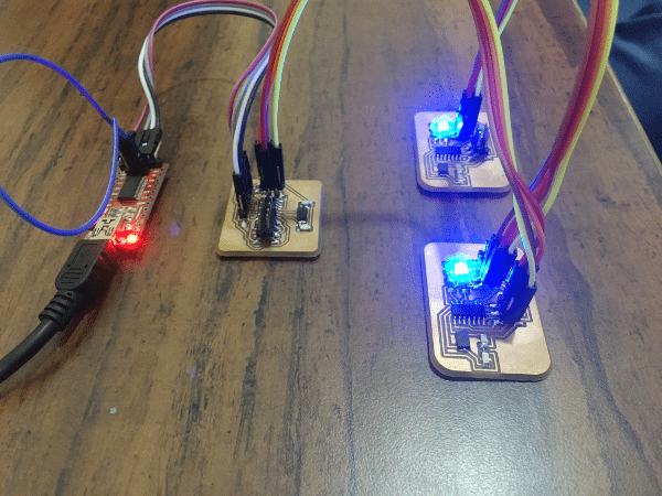
Final Outcome
Now for making a network we need to connect all the boards together...... for connections this is a schematic, how to connect the slave boards to master.

Overall Learning
- I learnt about I2C interface
- I was able to control relays and understand a way forward to connect to Alexa, again a major outcome for my project work i was able to achive this week.
- Very interesting week to get a chance to experience and learn networking and communication. I am looking forward to actually apply this week’s work to my final project for wireless communication.