4. Computer controlled cutting
The task for this week was to learn and implement computer cutting tools and techniques with the help of laser cutter and vinyl cutter machines. The goal was to characterize the machine, try different materials and apply different process parameters resulting to diversified outputs for practical learning.
-
Objective was to use parametric desiging using CAD tools we used in Week3. Also one of the group project was to work on the laser machine to identify the kerf of the cut so as to construct a press-fit kit.
-
Group Assignment to characterize laser machine
-
And finally to cut something from Vinyl
Softwares Download
- Laser Cutting RDWorks Download
- Vinyl Cutting GraphTech
Getting Started Laser Cutting
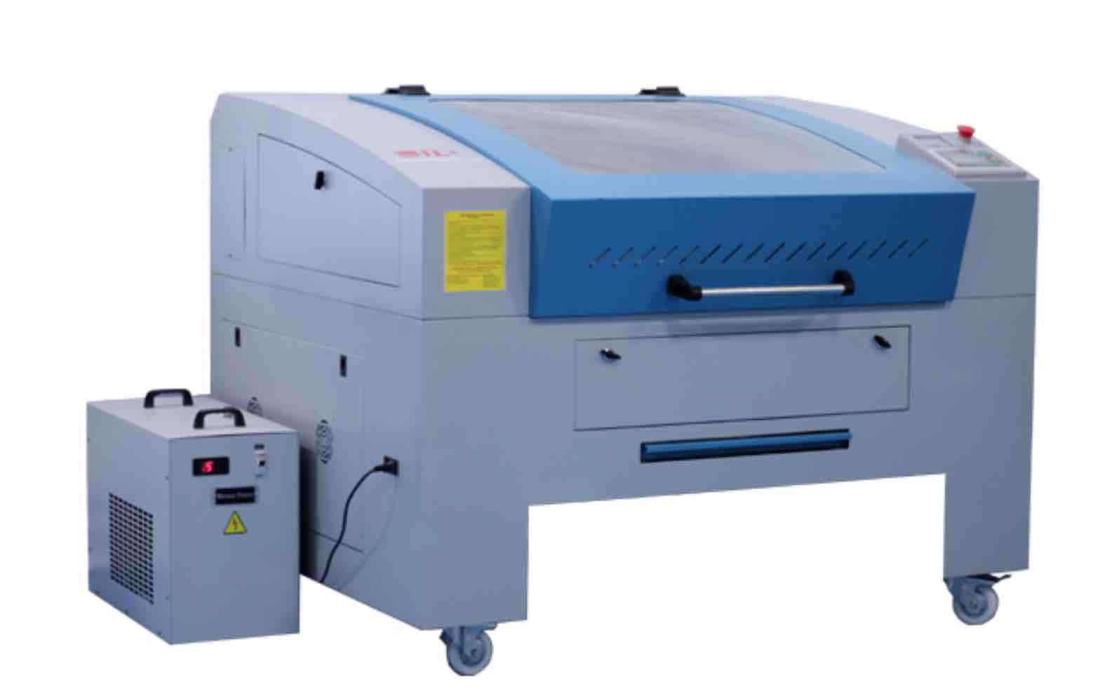
We started with the group assignment to characterize the laser. At AKGEC fablab and especially in India we use laser from SIL
As part of the group assignment below are the key tests we carried out. Also to note here for all the test files we used it was created by Ashish Sawhney in fusion. He is a returning student for Fab lab this year and so our team focussed on more laser testing part rather than designing part, which for me personally saved a lot of our efforts. So a big thank you and shout out for Ashish.
Understading how to operate the machine
Safety features
Key thing Neil mentioned on Wed lecture was that we should always ensure safety while operating the laser. So i looked for the key safety features that are in built in machine
- We have an emergency stop button
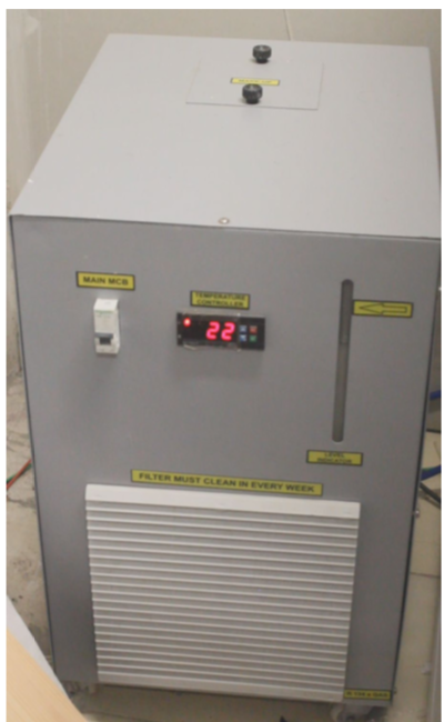
- We have display on Chiller that showcase whether we have optimum temperature maintained for machine
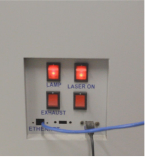
- We have an exhaust that can pull away harmful material fumes and burning material
- Ensure laser is off when you are not cutting. Only turn on laser before you start making cut when you are uploading files etc. or setting origin make sure laser is off. Check images in below for powering up machine laser is tuned on without exhaust been on, we should avoid doing it.
Powering up the machine
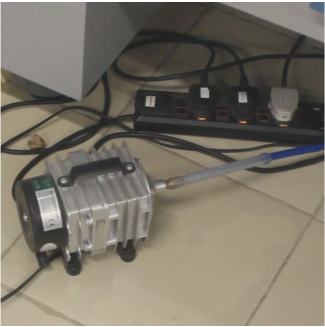
- Turn the machine, chiller and air compressor power on.
- Let the chiller temperature come down to about 25 degree celsius before we start using the Laser.
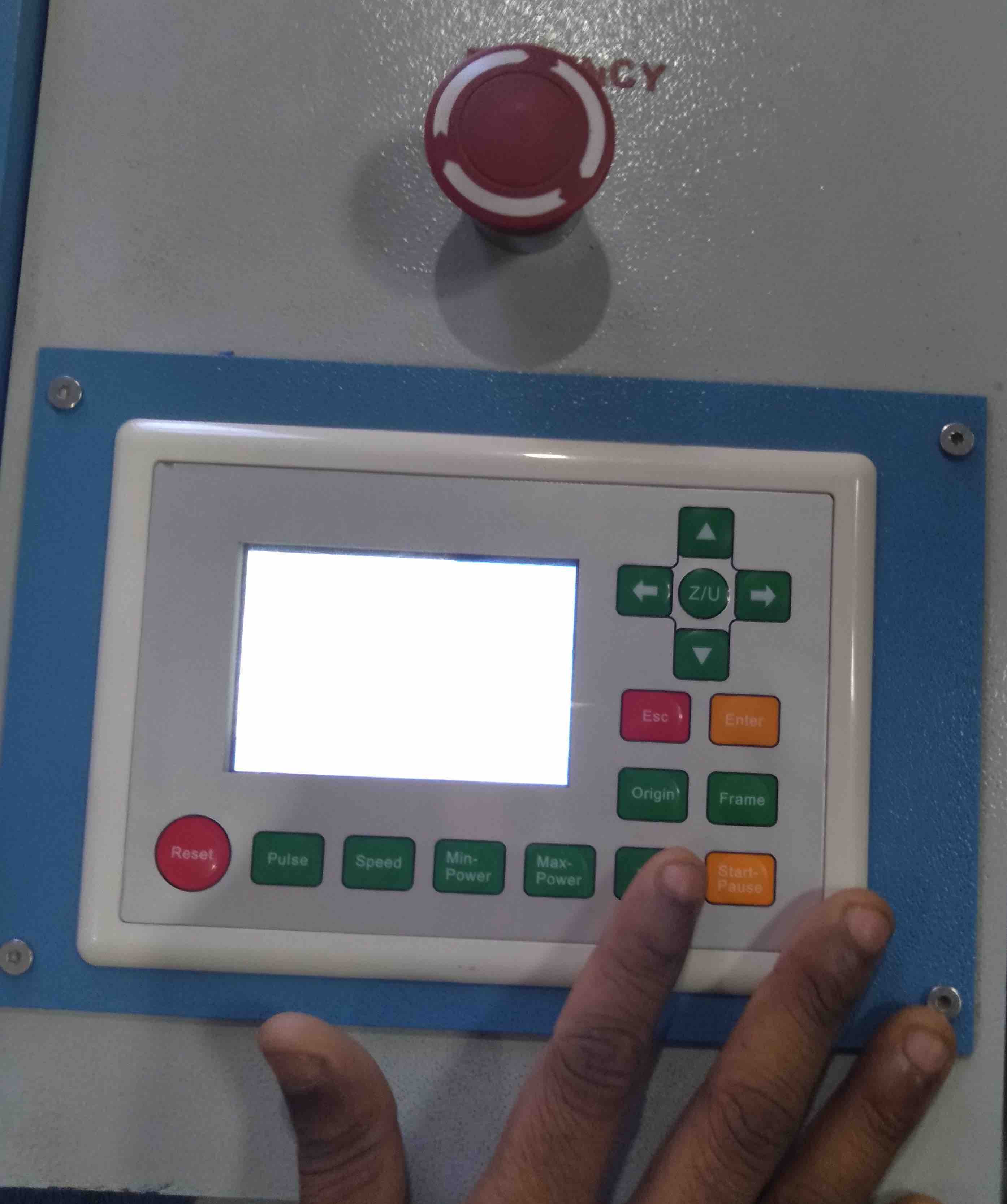
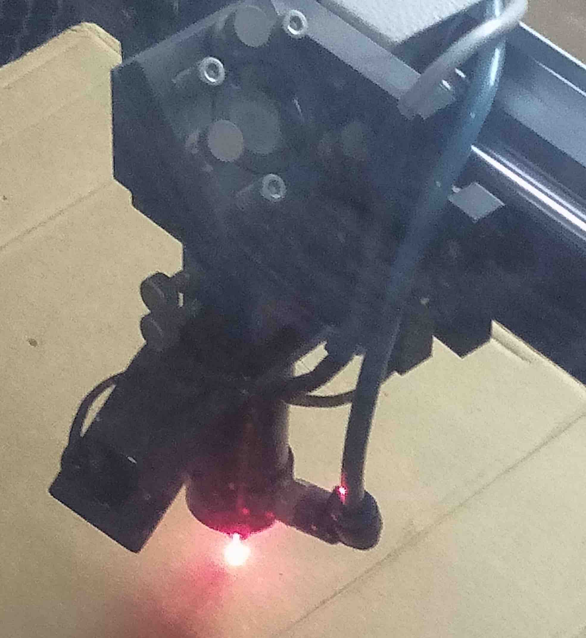
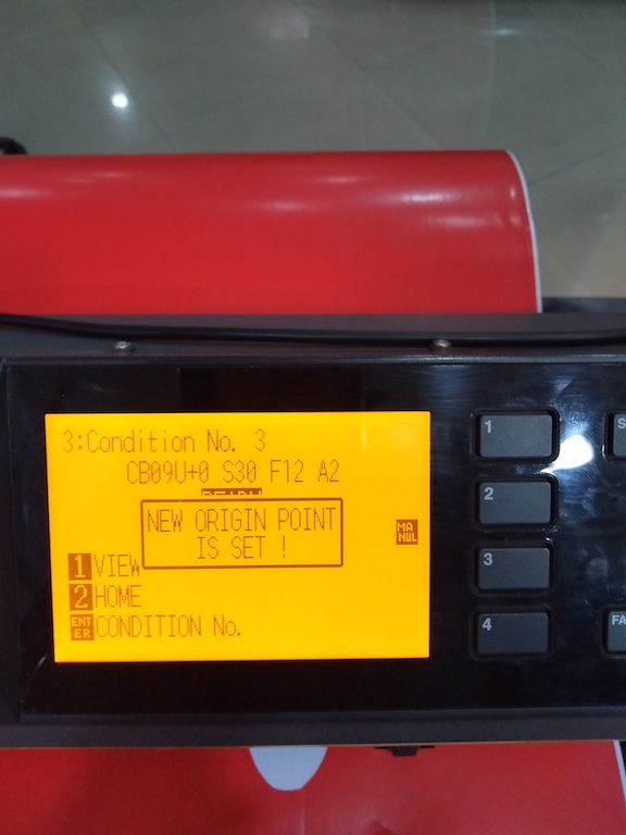
Setting focus point and Origin
- Set the focus before starting the print.
- You can use the Laser dot switch on the control panel to set the focus points.
- This switch will project two red dots on the material below.
- Adjust the Z-axis in a way that the two red dots perfectly coincide with each other to form one single red dot
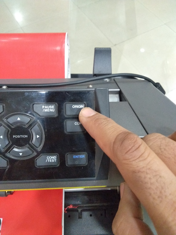
- The origin is always from the top right of the frame but it can be adjusted manually using Orgin and Enter button.
Materials we used for our testing
- Acrylic (Thickness 2mm)
- Cardboard (Thickness 3mm and 2mm)
- MDF (Thickness 2mm)
Test We Carried Out
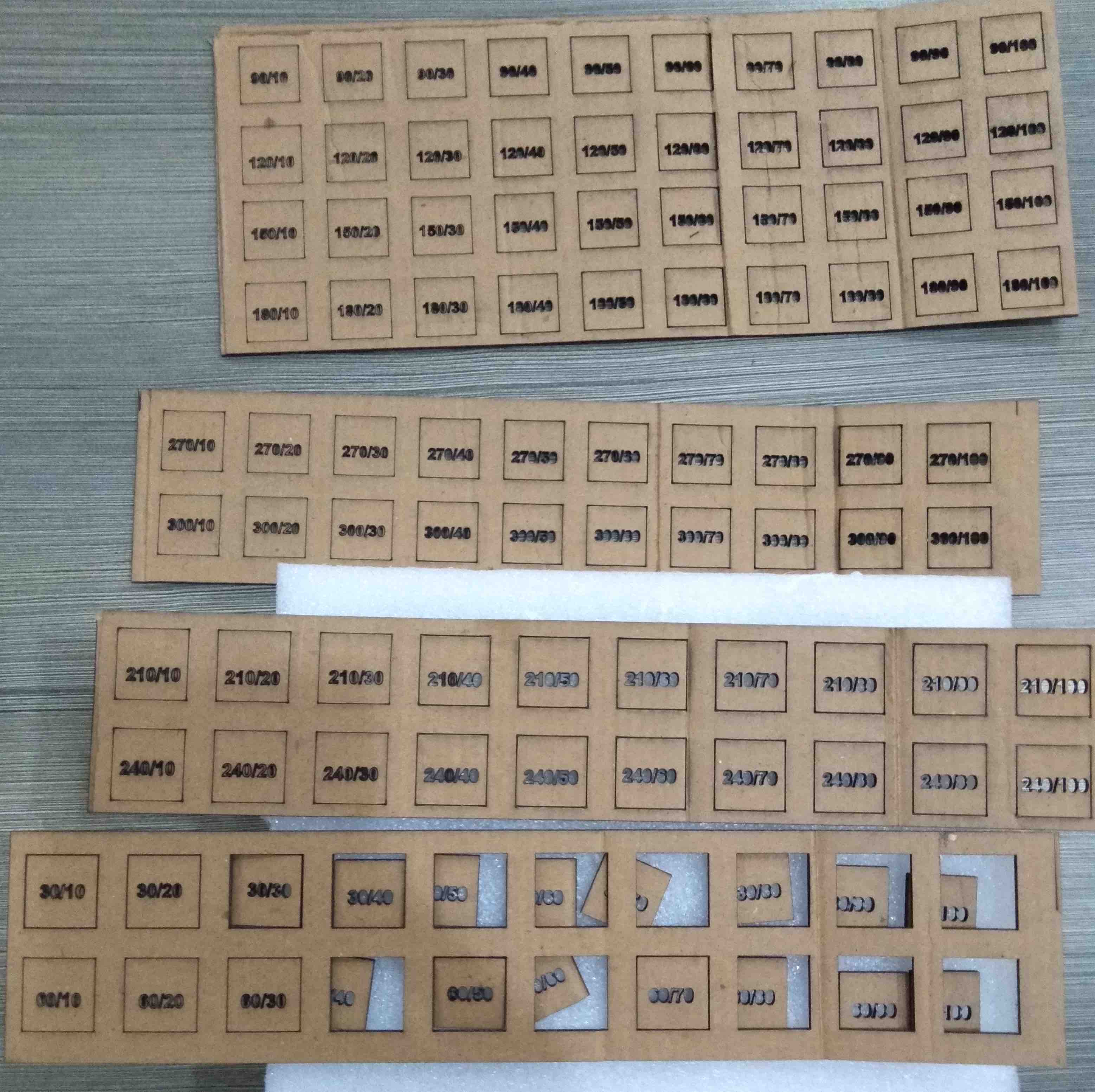
Speed and power test
In this test idea was to test out the speed and power combination for our laser. Key output was to check at what speed and power the material can be cut. So we cut out a grid of squares with each sqaure cut at varying speed (30 to 300 mm/sec) and power (10 to 100 percent) ranges
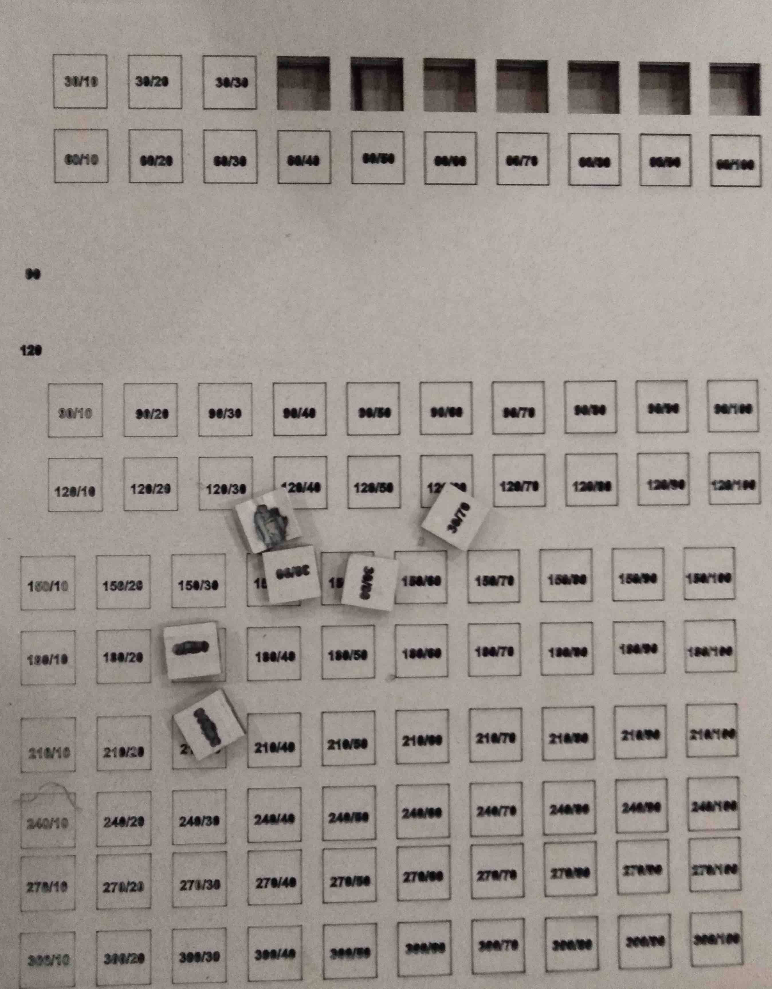
Key learnings from this test
-
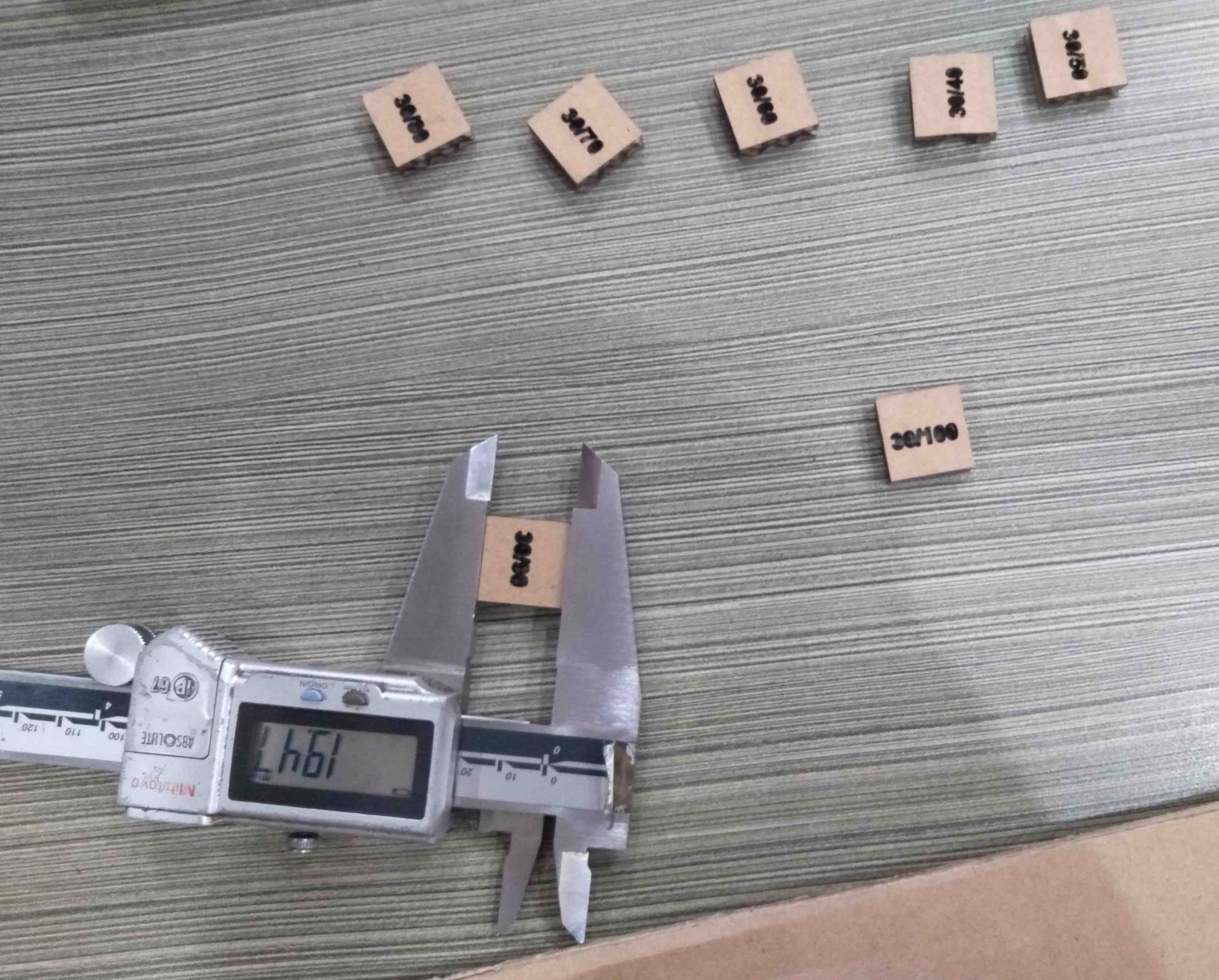
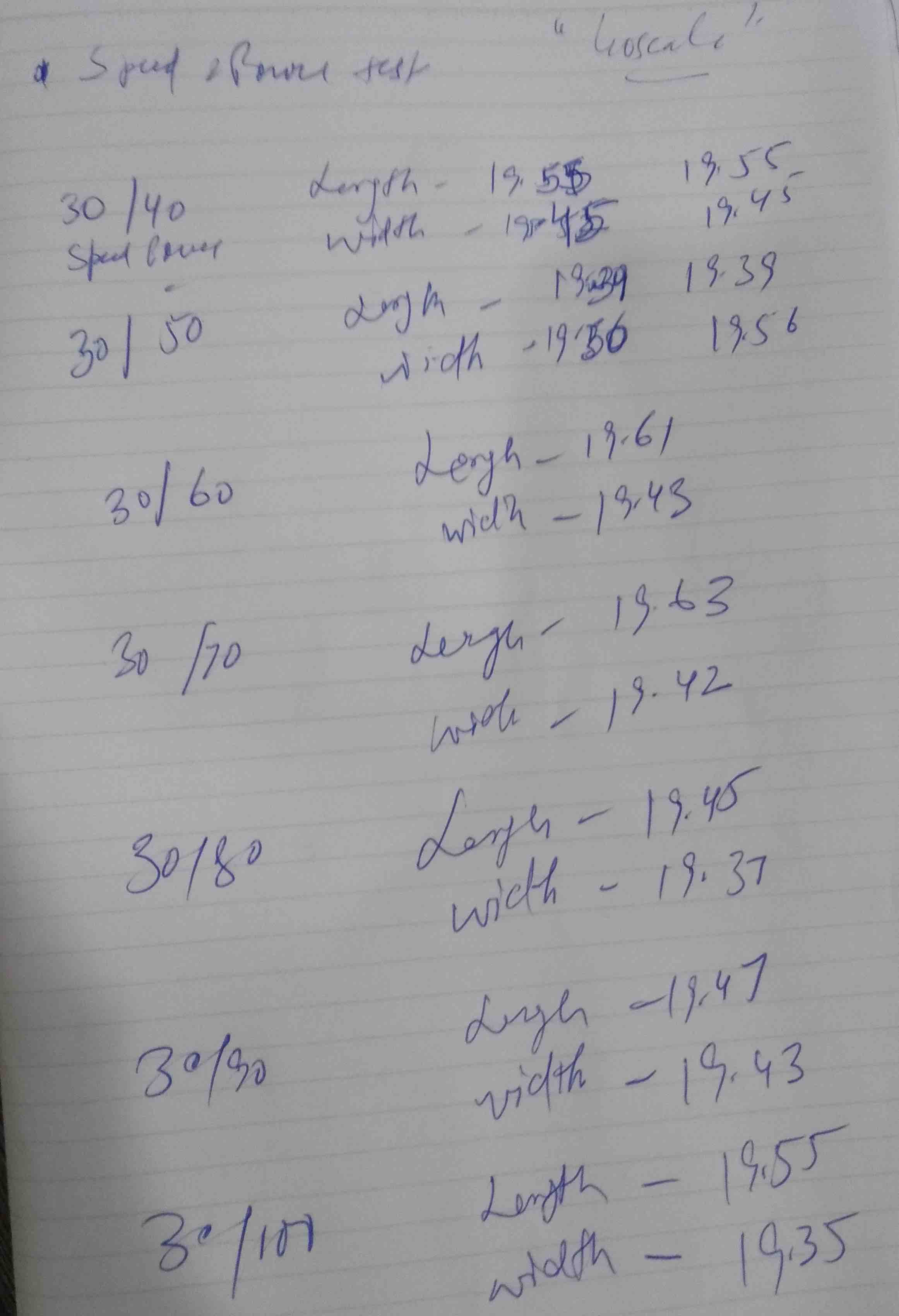
In short simple learning was that to cut material less speed is needed and power should be high. This allow laser to focus at one point allow more material to burn. For our test on Cardboard we were able to cut 2mm and 3mm thickness cardboard at following speed and power combination.
-
We don’ get exact dimensions after cut. So its important to set offset and calculate kerf for material. Here is what we have found when we tested the cardboard cuts using Vernier
Etching Test
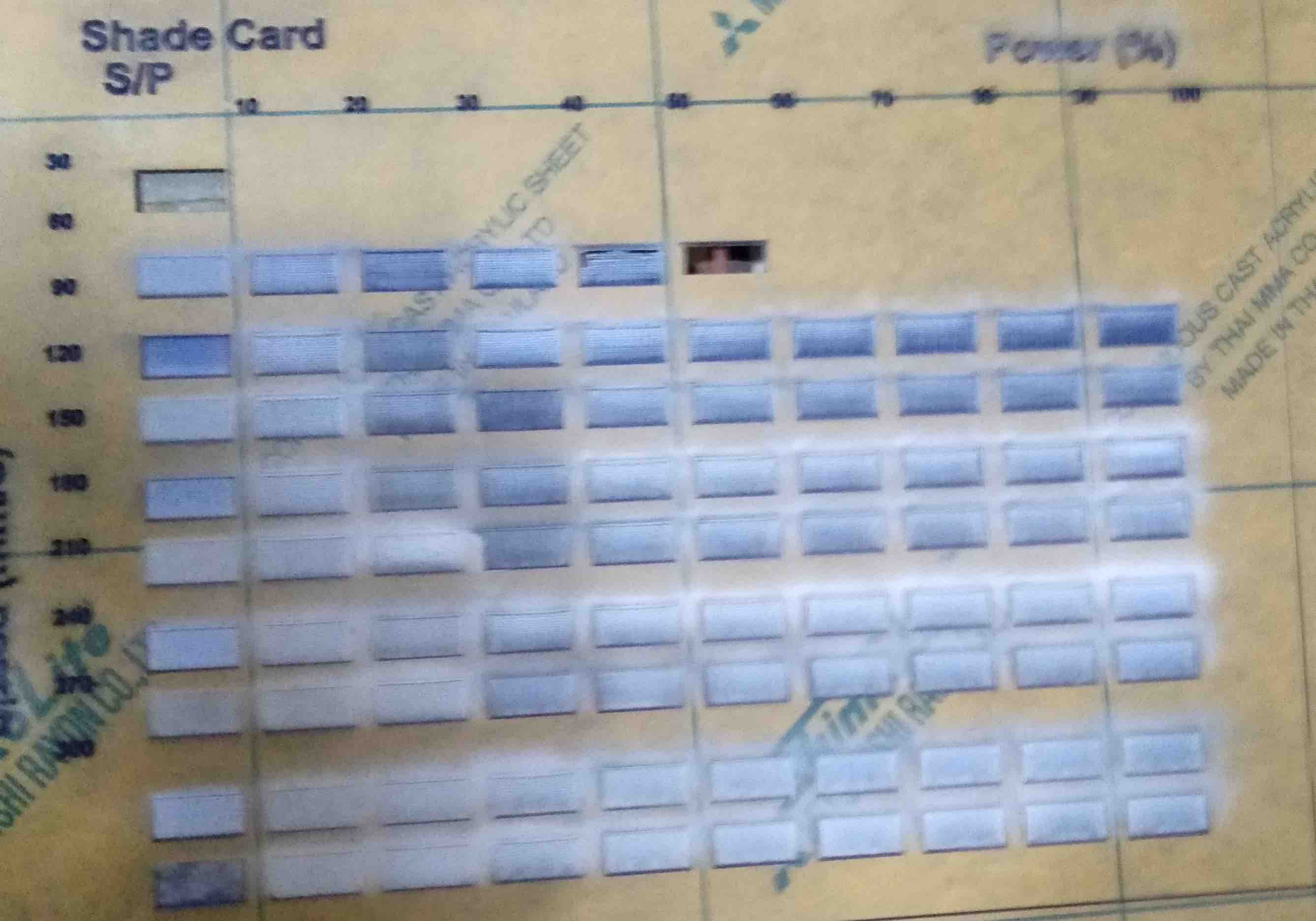
In this test idea was to test out the speed and power combination for our laser for scanning. Key output was to check at what speed and power the material can be etched to create shades. For this test we decided to use Acrylic. So we scanned same grid of squares with each sqaure scanned at varying speed (30 to 300 mm/sec) and power (10 to 100 percent) ranges on acrylic.
Key learnings from this test
-
Key learning for me was that itching a material is completely opposite to cut test, so less speed and more power would just cut the material. So for etching high speed is needed.
-
Also in scanning the laser moves x and y axis repetatedly so the movemnet of laser was different as compared to cutting
Comb Test / Calculate Slot Size
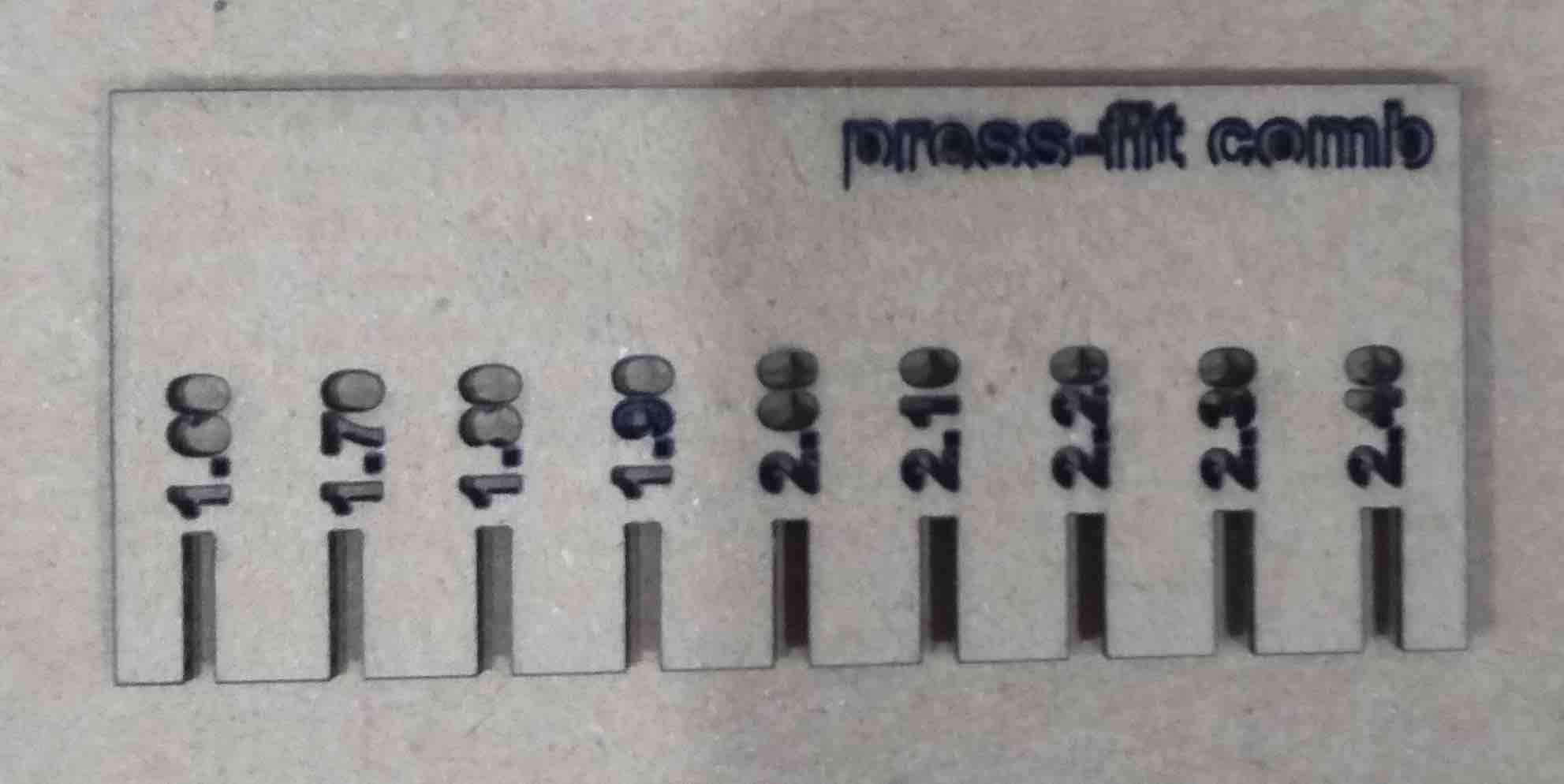
One of the individual assignmnet for this week was to create a press fit kit and calculate a combination of slot size for a material that gives us a good slot fitting. We used MDF for our test becasue we had lot of stock available for this material. So basically we created a comb with different slot size and try to fit it with the material through which we made it.
Key learnings from this test
- For the MDF of thickness 2 mm we had a good fit for 1.8 mm slot in comb.
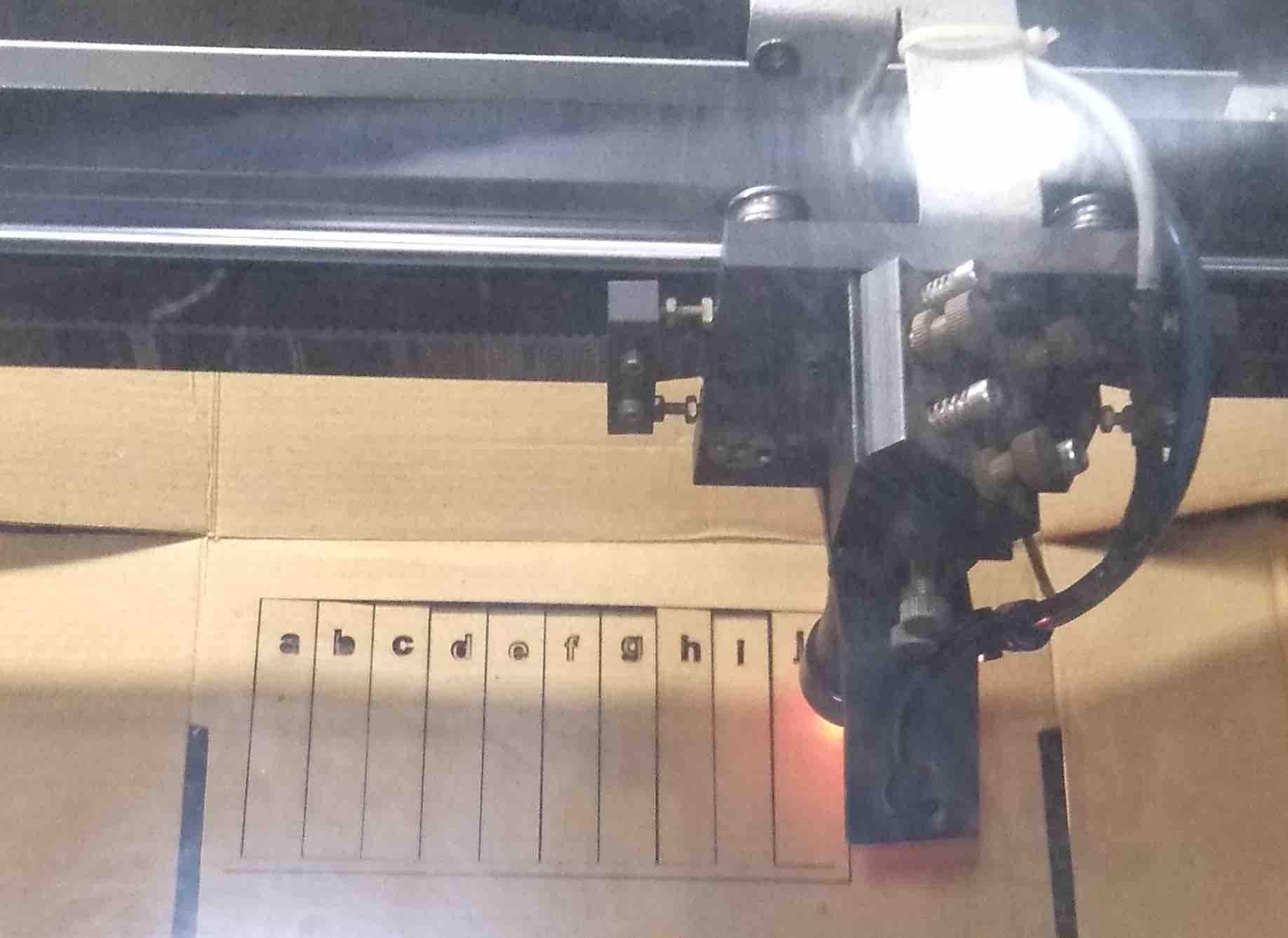
Kerf Test
What does kerf mean?
The laser burns away a portion of material when it cuts through. This is known as the laser kerf and ranges from 0.08mm – 1mm depending on the material type and other conditional factors
For Measuring the KERF we made 10 cuts within a rectangle and the shifted all the cuts to one side, then measured the gap, and then divided the gap by 10, the final obtained value is the KERF of the laser cutter we are using, which is in our case is : 0.3mm
Key learnings from this test
- Calculation is as : Distance obtained after the cuts are shifted to one side = 3 mm and the total number of cuts = 10, So 3/10 = 0.3mm which is the KERF of the LASER.
Press Fit Kit Design
This week assigment was to create a press fit kit using laser machine which should be parametric in nature. Doing the group assignment helped me to determine the material thickness, power and speed setting to cut the material. I used Autodesk fusion to design my parametric kit which i learnt in Week3.
Autodesk Fusion Design
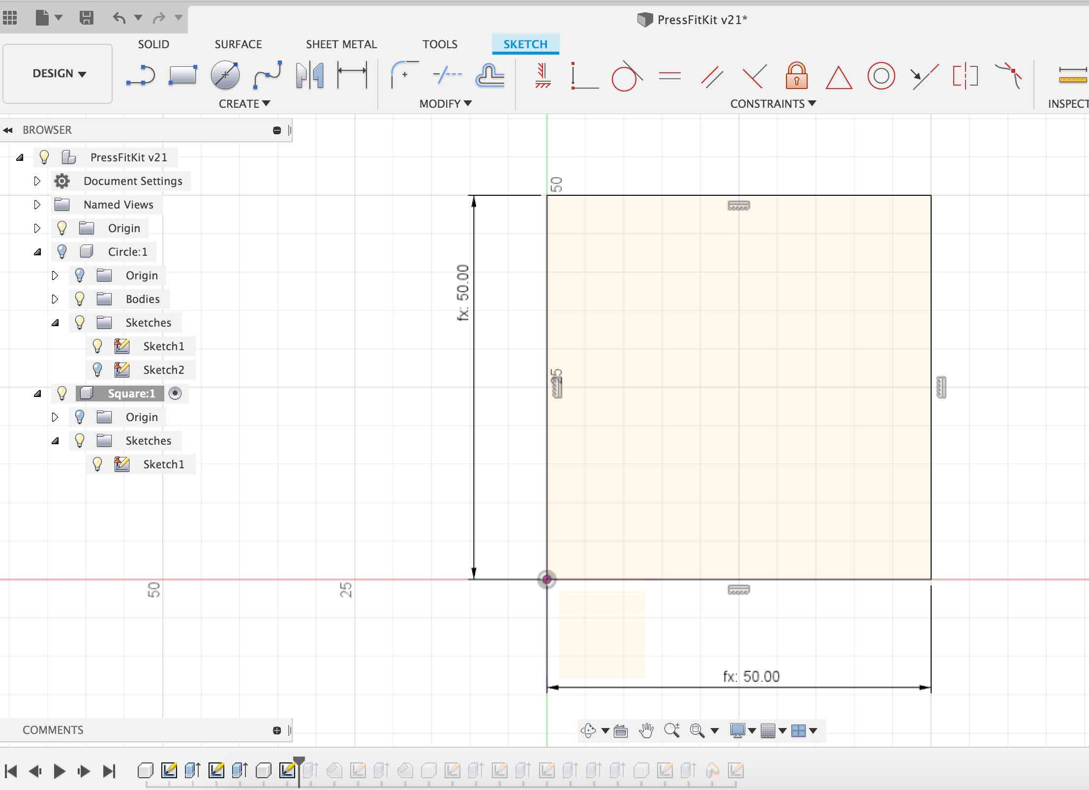
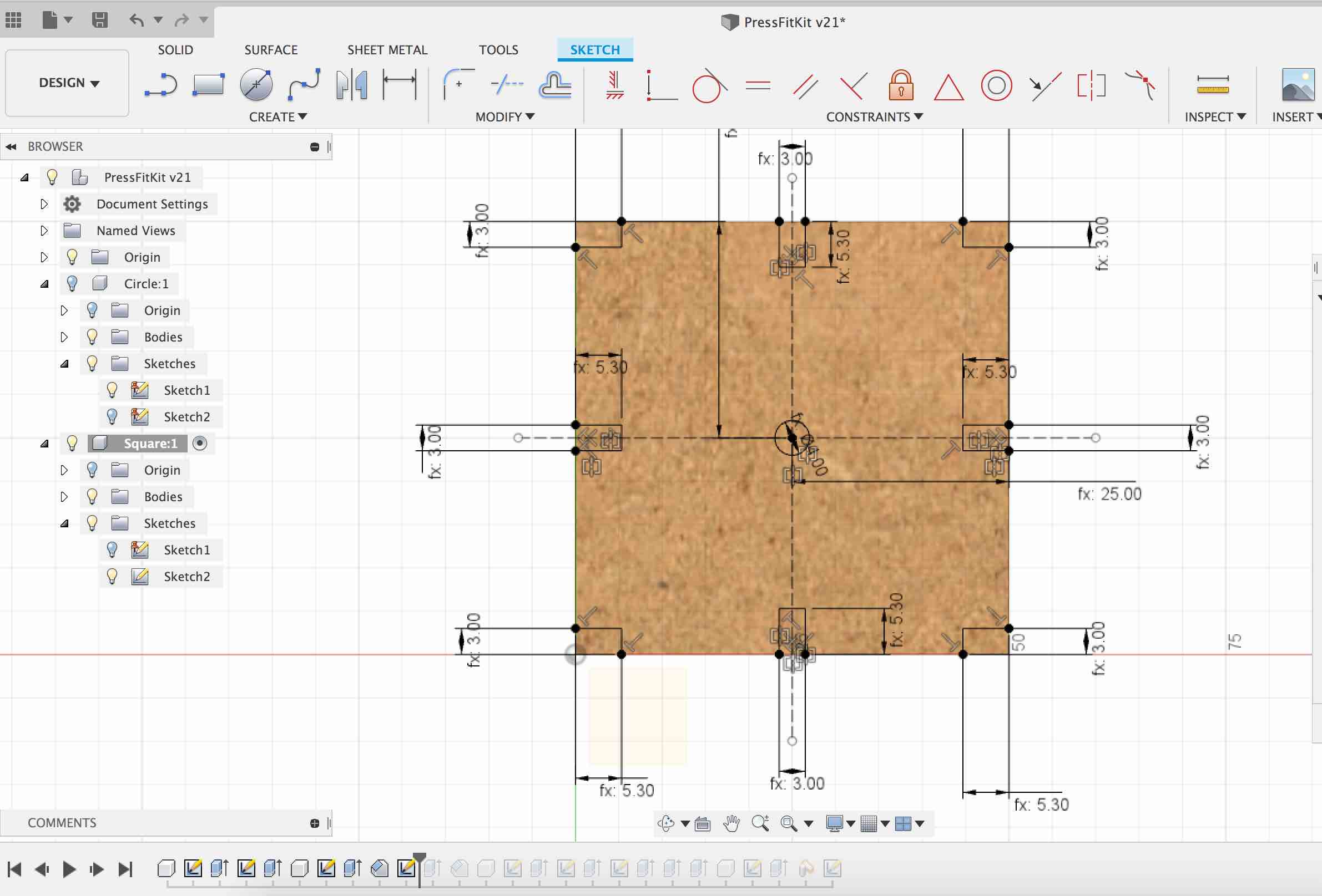
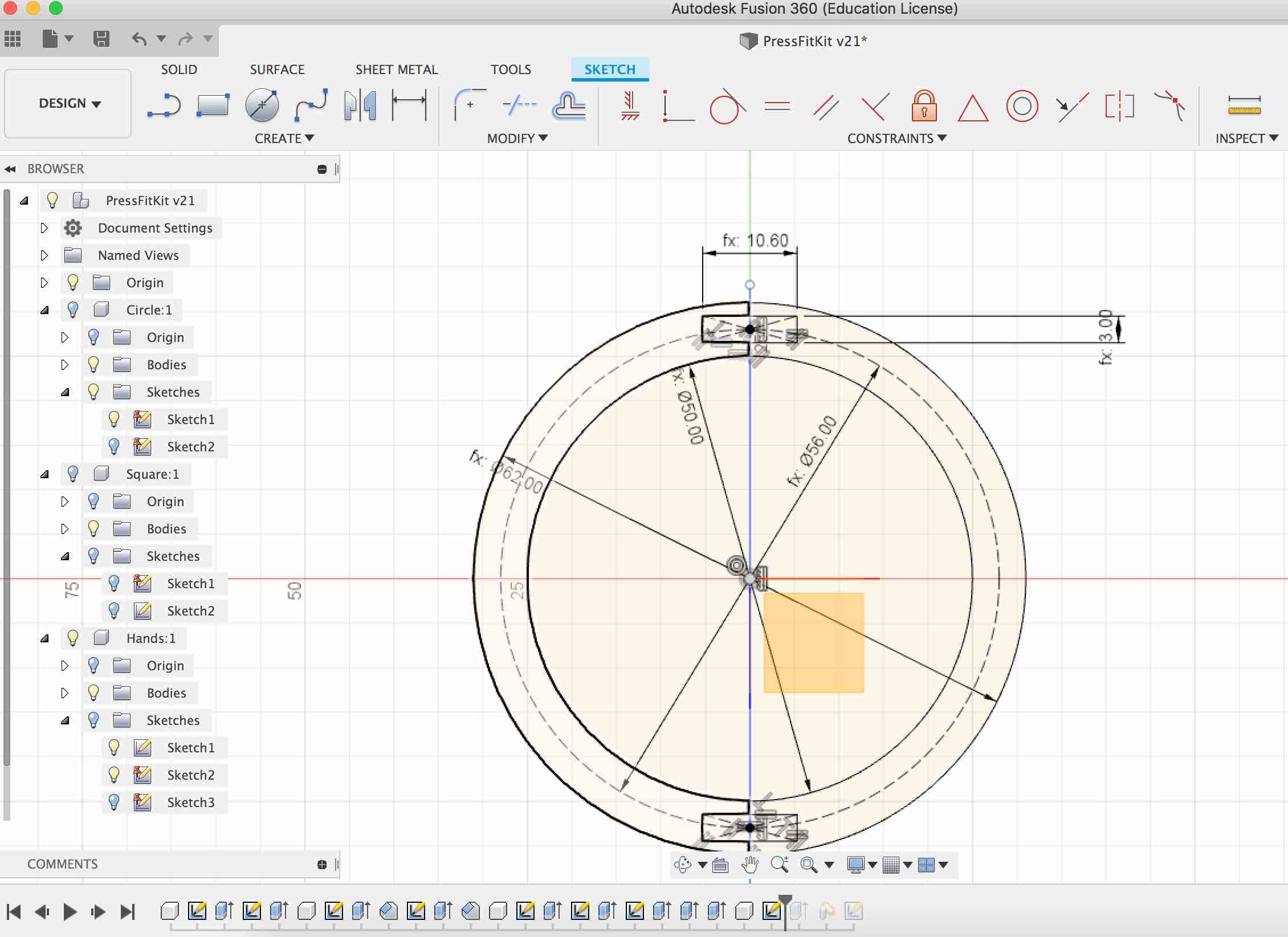
I added various parameters in fusion for which accounted for Kerf, material thickness in design itself. Download link for fusion file
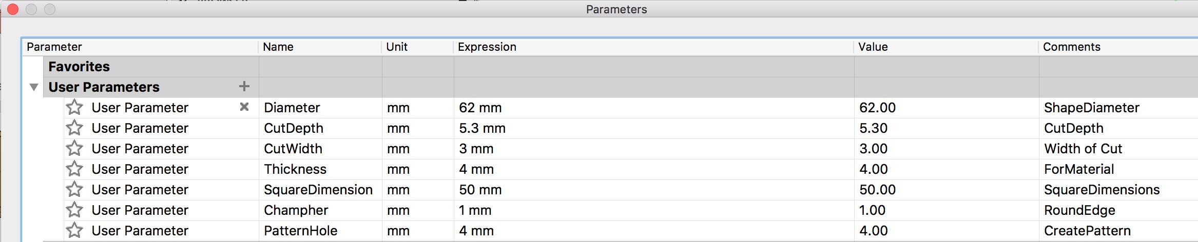
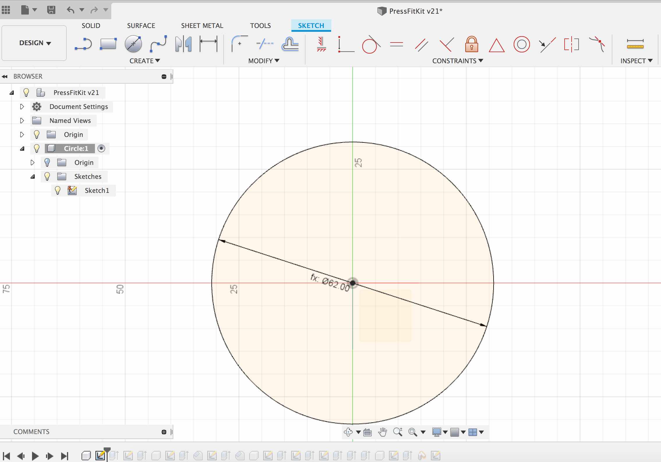
Basically i designed three parts for press fit kit. A Circle, a Square and an Arm to connect them together. I have attached the fusion file and you can quickly go through the design timeline to understand how i have designed this. But for summary here are few steps
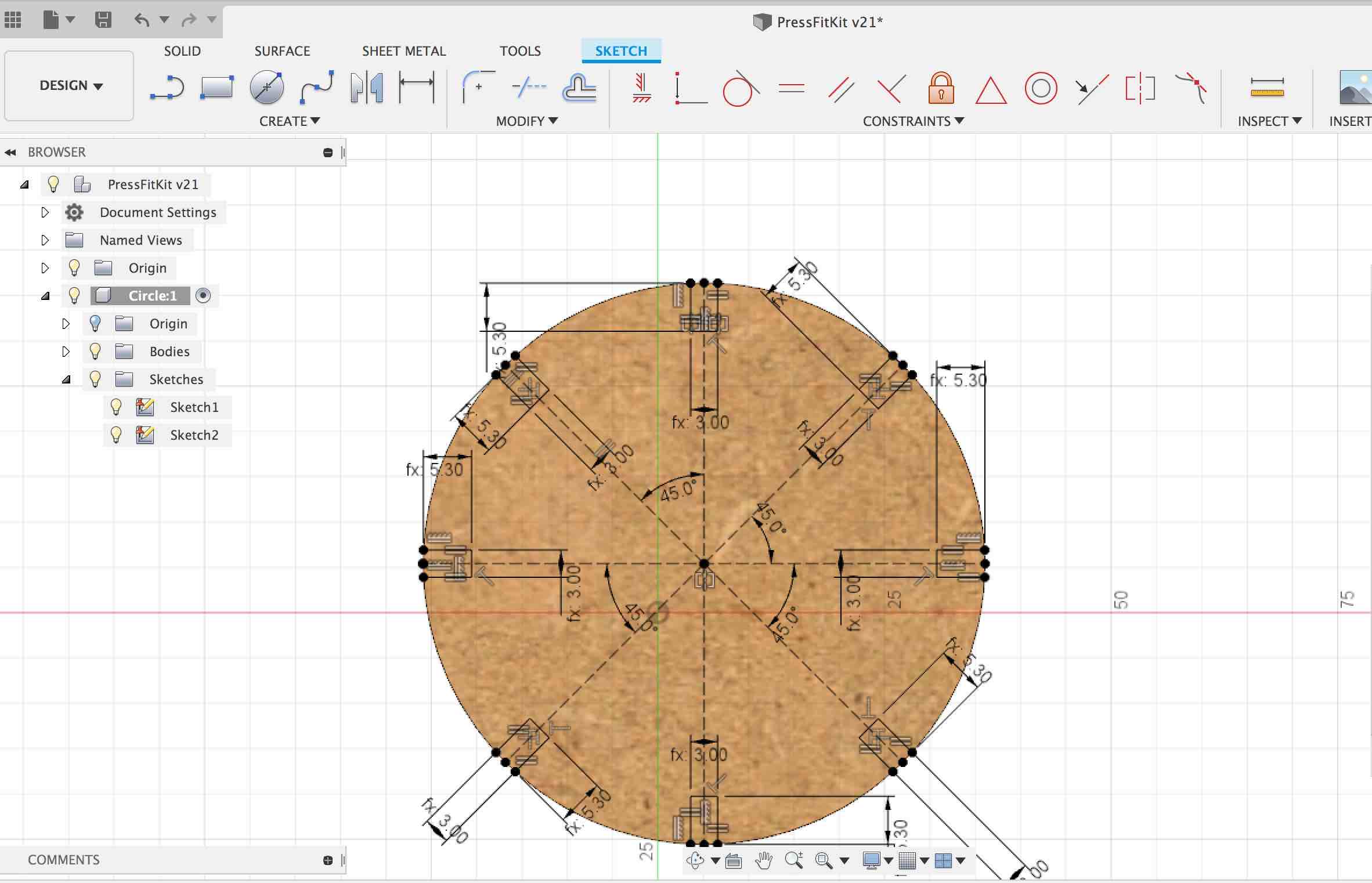
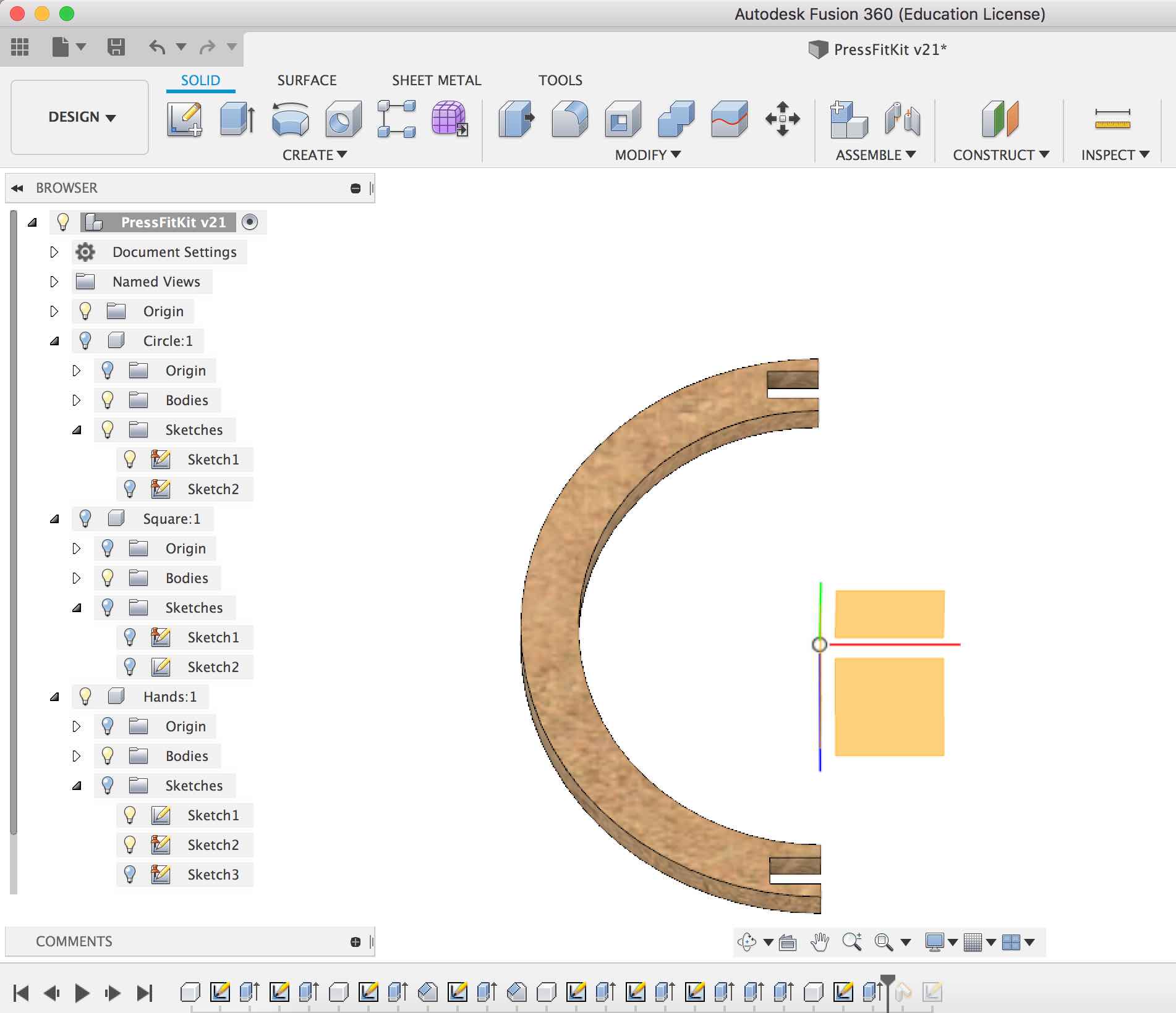
- I started with circle first created a sketch and drawn a circle. For press fit i wanted various sections in circle so i created another sketch using earlier sketch and used extrdue command to create the same.
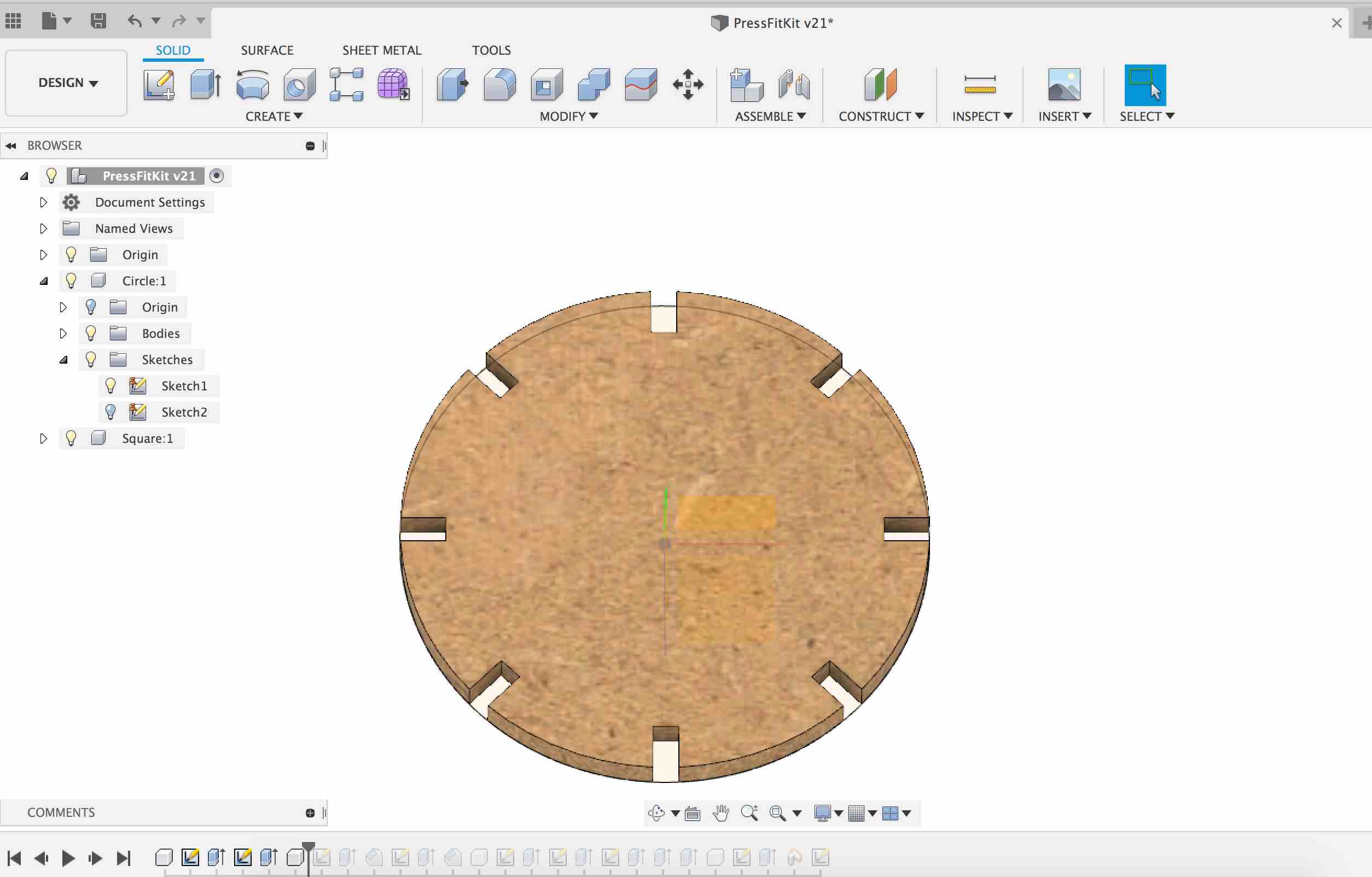
- Next i designed a rectangle and followed similar steps for it.
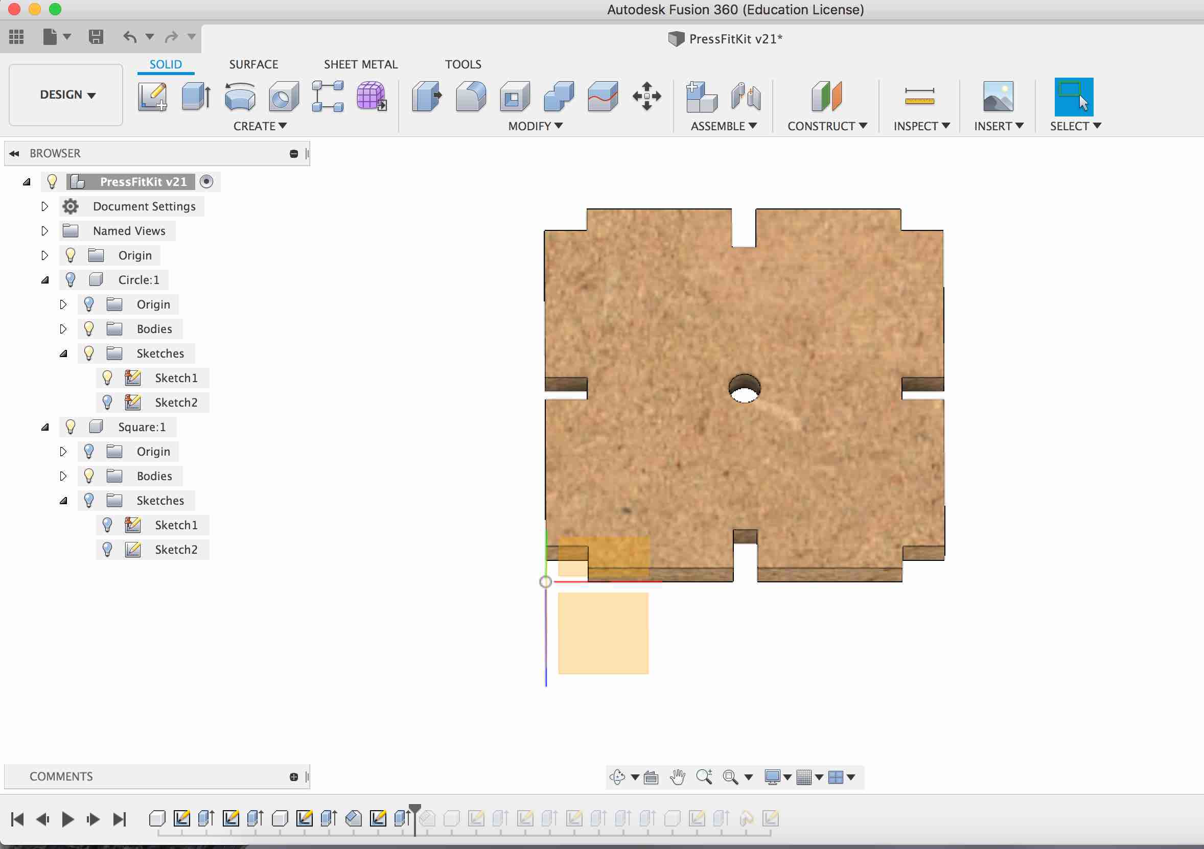
- Last i designed the arm to connect both pieces.
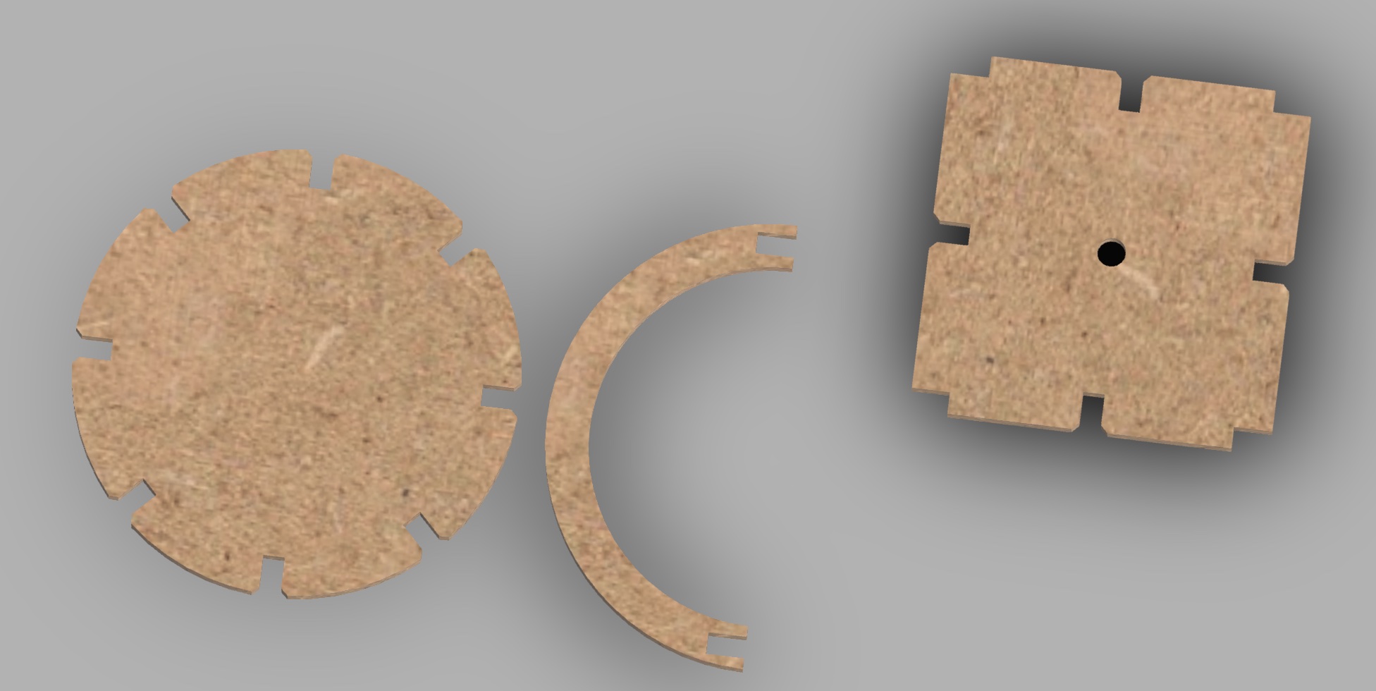
Rendered image for press fit key components
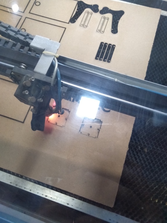
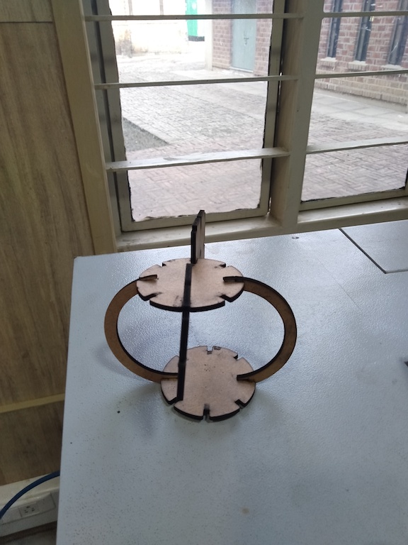
Laser Cutting
PressFit Combos
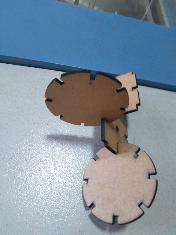
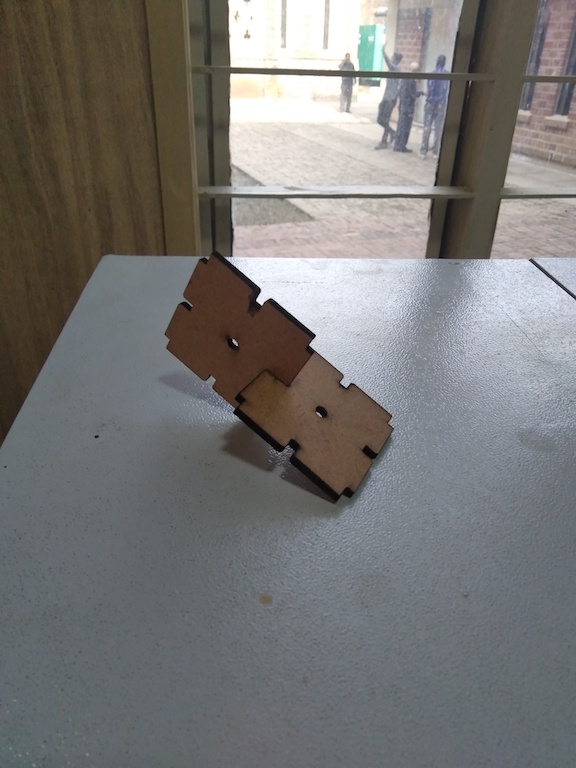
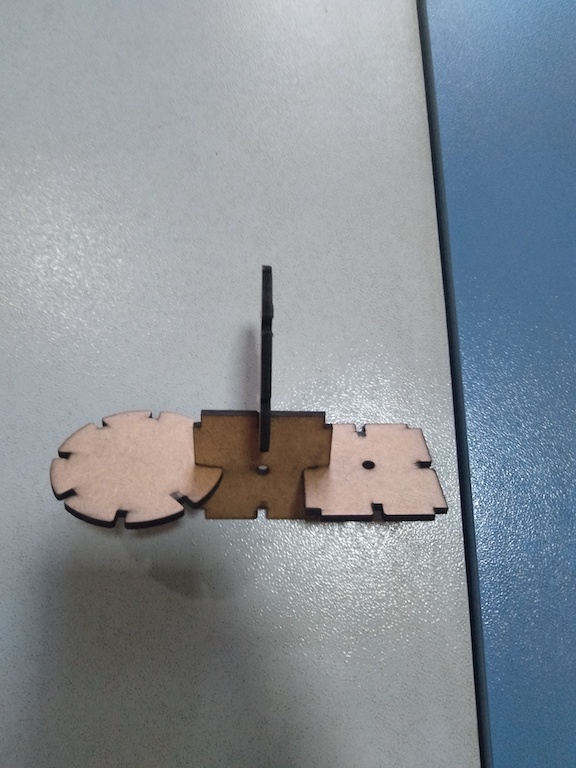
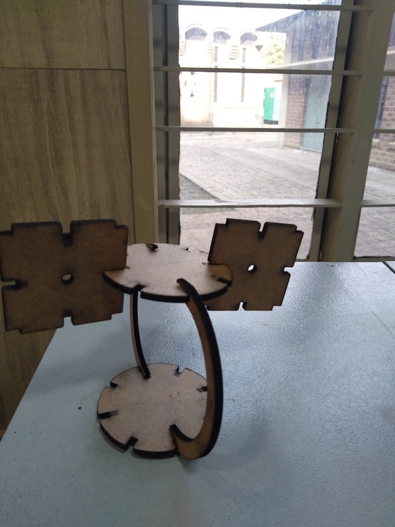
Vinyl Cutting
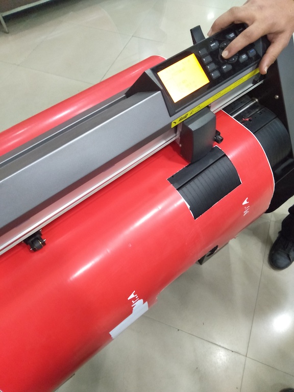
Getting Started Vinyl Cutting
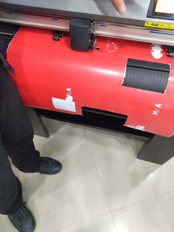
At AKGEC we are using vinyl cutter from Graphtech
Key activities i did on the machine.
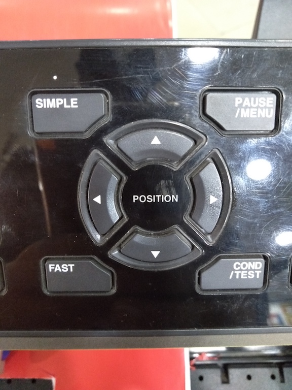
Understanding Key controls on machine
Setting vinyl X and Y position for material to cut
Set Origin
Similar to laser we had Origin button on machine which we use to set postion from where the machine will start cutting.
Designing the image for Vinyl Cutting
-
First i downloaded a batman sticker from google
-
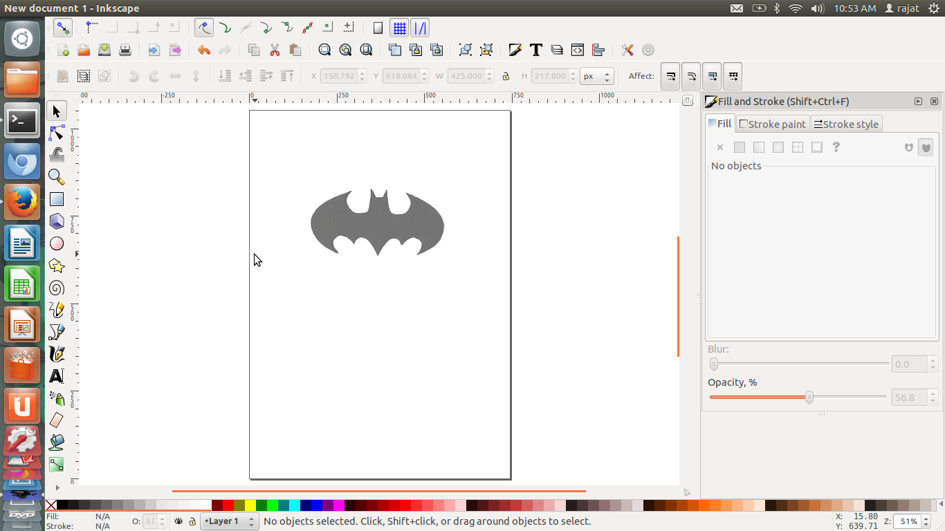
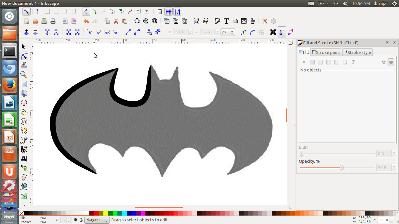
Next i opened this up in Inkscape that i learnt in Week 3 and using edit feature reduced the opacity to 57%
-
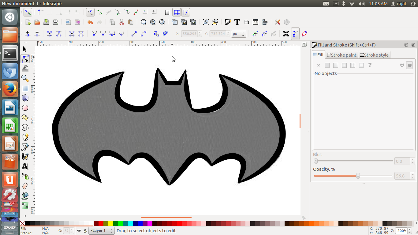
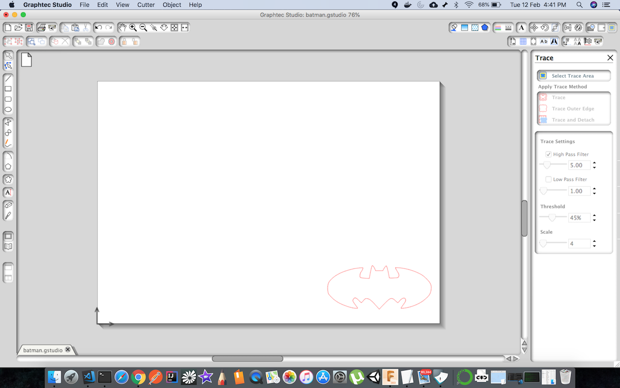
Next i used the feature of Inkscape which is bezian curve to trace the bitmap image
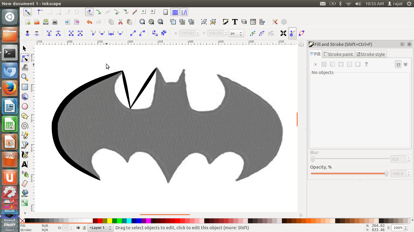
- Using edit node feature i was able to get required curve of the line
-
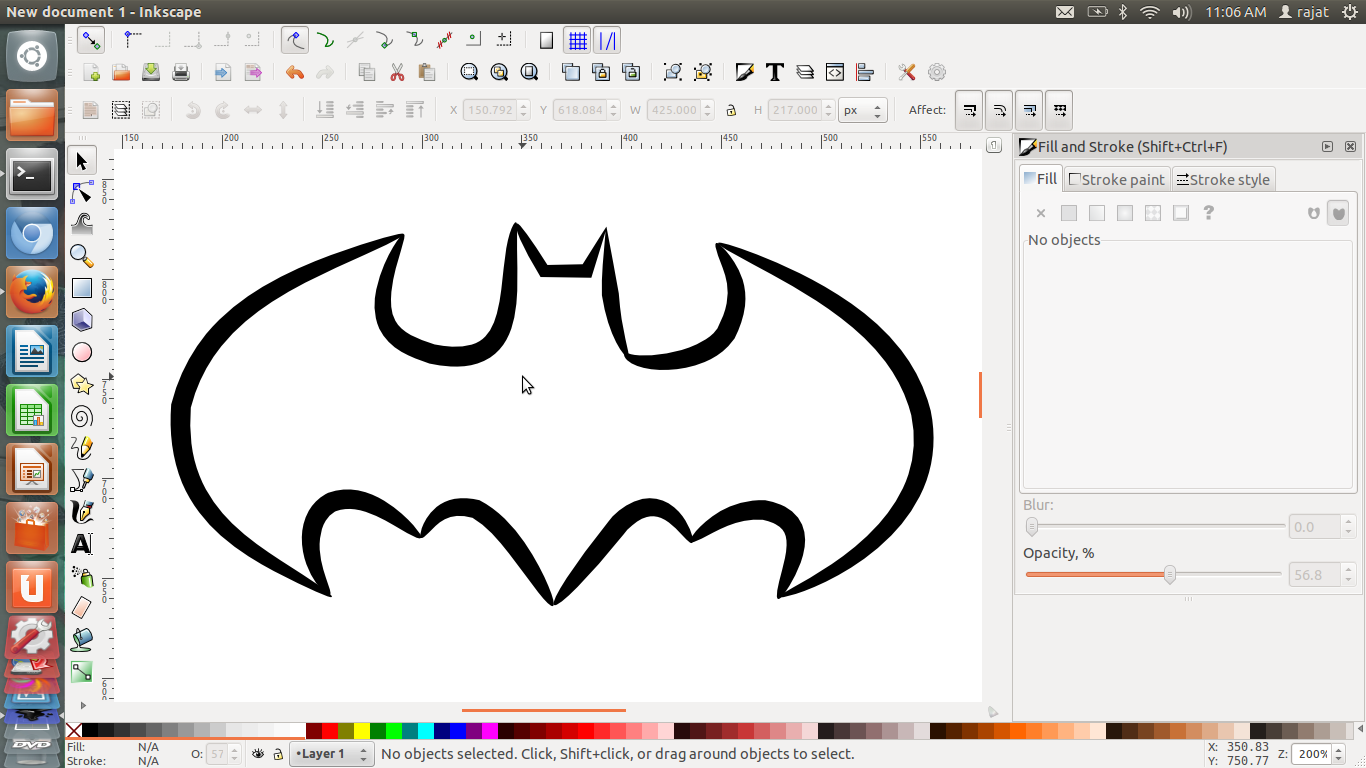
Final image that i traced using bezian curve and edit node feature
-
Last i deleted the imported image to get the required batman logo
-
You can downaload the final svg file here
Opening the image to cut in Graphtec Studio
Issues with tracing
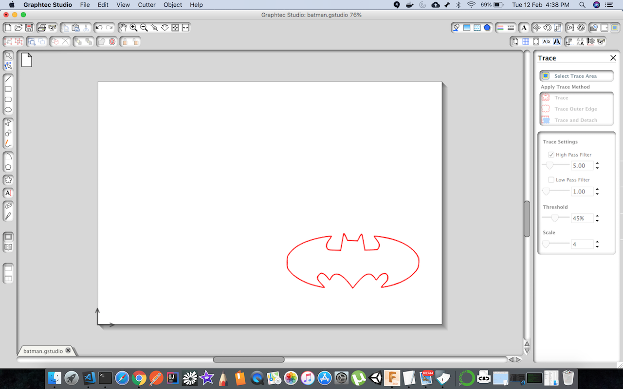
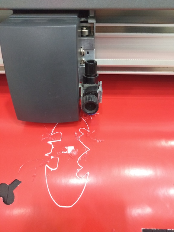
When i imported the above batman image and ran trace command in graphtec studio it actually taken a double line instead of single, as you can see in above the image outline is a bit thick. So it resulted in running the cutter multiple times on same area. Key learning for me was that for tracing we need to trace that result in a single line trace causing vinyl cutter to cut only once.
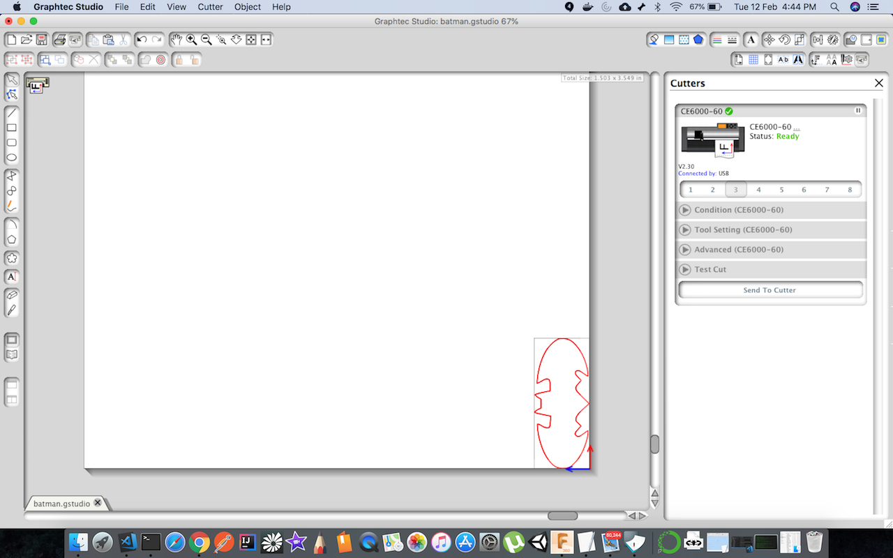
Fixing the trace error
This time i selected the trace outer and it resulted in seperating the two layers i had in image, i deleted the one and only left with single line.
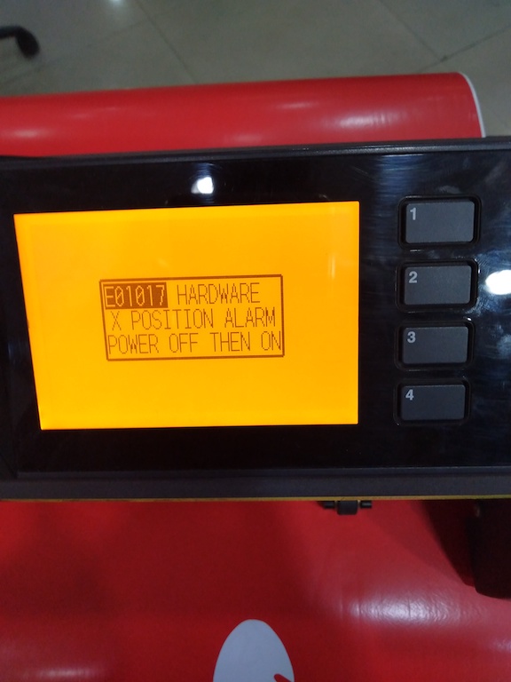
Weird Hardware error
As checked with our lab manager the reason was when both sensor of machine and roller comes into contact of area where there is no material at once it results in this error. So i changed the machine origin a bit and was able to fix by turning it off and on.
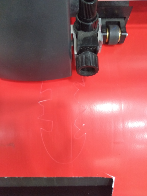
Sending the final design to vinyl machine
Cut operation
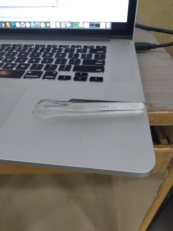
Pull Out Sticker
As image was small in size so i used plucker to peel the image. Have not tried transfer tape as it was not available in lab.
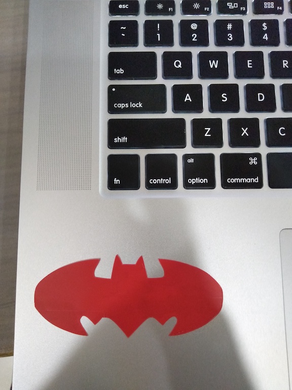
Final Product
Now batman is all black unfortuantely in lab i don’t had black material so used RED material to cut the image. It does not look cool on my laptop.
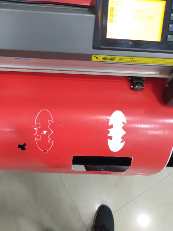
Avoid waste
One key learning for me was that in setting the origin we need to ensure that we set it properly. In my experiment on vinyl cutting i set origin at random places causeing material to go waste and had an earful from our lab manager on this. So a good lessoon on using the material approprately in lab.
Key learning from this week
- It was hectic week to be honest with group assigment and personal assignment the load has increased.
- Key thing for this week is that now i can operate both vinyl cutter and laser machine and design a parametric press fit kit
- It also gave me insight on how to use the laser cut and vinyl cutter for my final project idea and how to leverage these machines
- I will be using Vinyl cutter to create some cool logo for my final project
