5. Electronics production
-
This week our group assignment was to characterize the specifications for PCB production process in a group and then as an individual assignment i had to mill a Fab ISP board which is basically a programmaer which is to be used in further upcoming weeks for programming of other boards.
-
After milling the components should be soldered as well as programming of the board was also one of the tasks
-
As being an IT engineering background it was completly new skill for me. I was very excited for this week because apart from the old school academics that we are taught in college I was going to produce my own pcb by milling it and doing the practical application
Getting Started
PCB Milling is the process of removing areas of copper from a sheet of printed circuit board material to recreate the pads, signal traces and structures according to patterns from a digital circuit board plan known as a layout file.
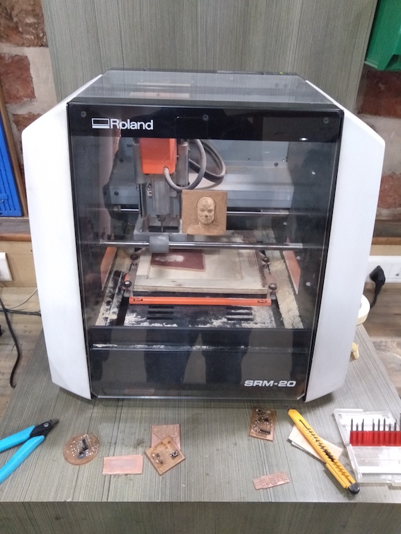
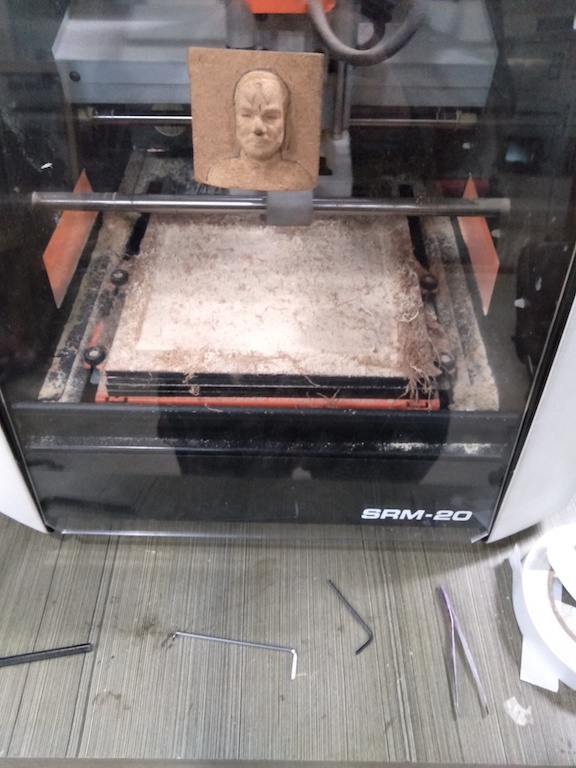
In the fablab we have Roland SRM 20 desktop CNC machine availale.
Group assignment
Important Links
- Fab Modules
-
All of the below steps are explained further in personal assignment with images. But here is a high level workflow of steps that are required to mill the board.You can find more details on our Lab Group page

Understanding Mods
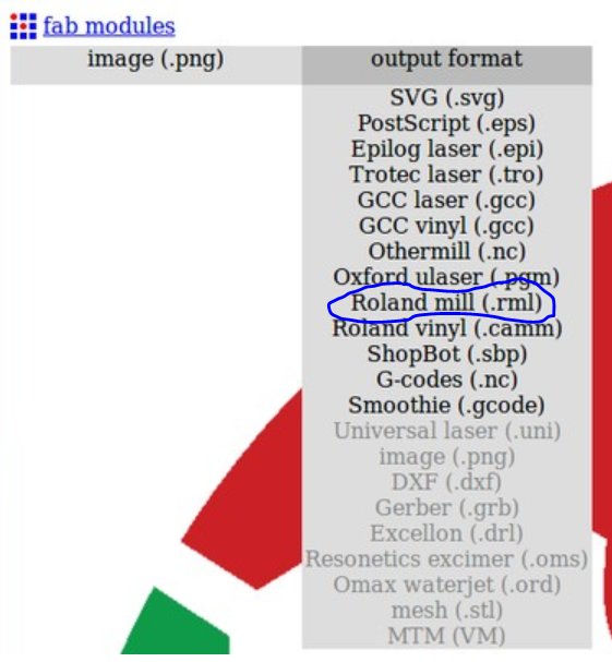
Fab Modes is a simple web interface application that clubs together various useful softwares written by Neil that are required to operate fablab digital fabrication machine. e.g. SRM needs .rml File and mods help us create it from the program to select PNG image and convert it into .rml file.
Understanding Vpanel
Vpanel is the software we used with SRM 20, in this we setup x,y and z position for the end mill by checking proper levelling. Below is the video showcasing the operation.
SRM needs .rml file which is basically G-Codes. This was a new term for me G-codes, which is a language in which people tell computerized machine tools how to make something. Also using mods we convert the PNG file into .rml file needed for SRM which can then be used in Vpanel software.
Milling workflow
- Making of the PCB design (we omit that this week)
- Conversion of the design file into .png format file with a high resolution say above 1000 dpi (dots per inch).
- Converting that .png file into .rml extension by going to fabmodules.org
- Selecting the input .png file
- Selecting the output as .rml
- Now selecting the Process and Machine (SRM-20)
- Setting some pararmeters the calculating the tool path and finally downloading the file.
- Setting up the end mill (we use 1/64 end mill as 1/32 flat end mill was unavaiable)
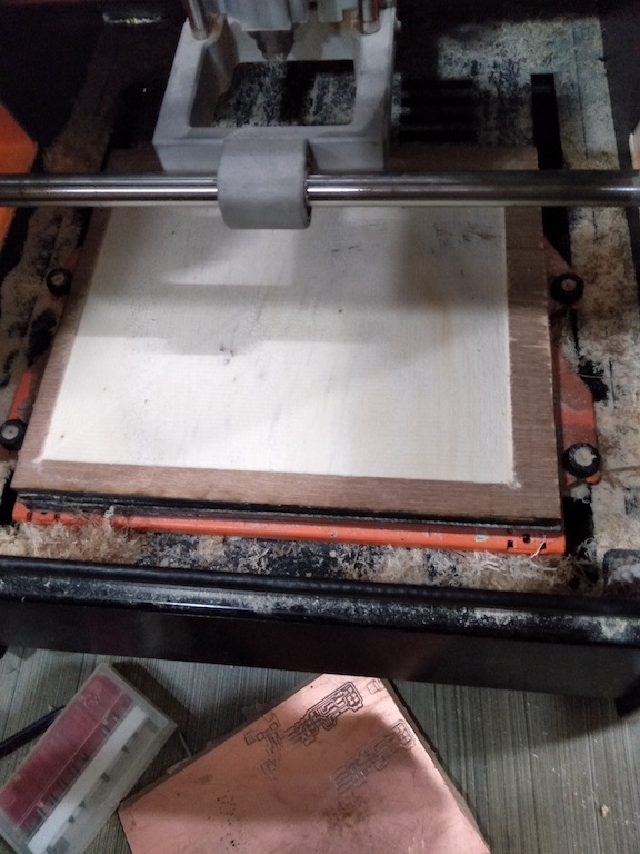
Understanding Surfacing
Surfacing is a process by which the bed for SRM 20 is levelled. Its very important that the bed is levelled before we mill any PCB. If bed is unlevelled it may lead to poor traces or broken bits. Example below.
Like we milled the board before surfacing resulting in wrong traces.
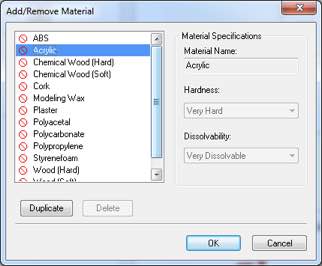
So we understandood the process of surfacing. For that we need to put a scarificial layer for PCB and use software ClickMill
-
First step is selecting the material type for scarifical layer
-
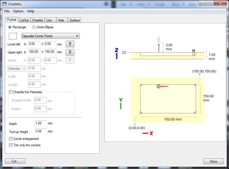
Next to select a pocket rectangle area which will be levelled and we can place PCB boards to mill
-
Next select the bits and perform cut operation.

-
Final results
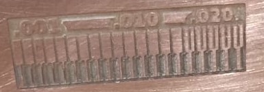
Group assignment Conclusion
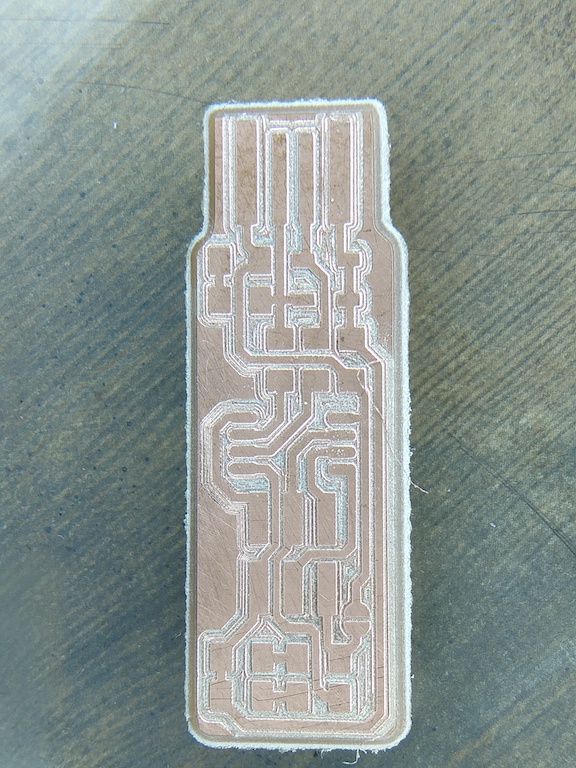
- In this mill job test tracks. Whole idea was to check the capability of machine and see tracks quality. To avoid short circuit we needed to avoid the thin tracks. For our assignment we were able to mill to the last of .001 trace using 1/64 endmill and it clearly milled to the last of .001 trace in a good manner.
Personal Assignment
Step-1 Selecting the Fab-ISP
- There are various versiions of Fab-ISP one can choose any one to make I decided to make Brian’s ISP.
-
Moving on the next step of the assignment and the most intense in my personal experience was to solder the important electrical components on the board.
-
So i started with some basics for electronics class on instructables, which covers basics for soldering, electronics components like capacitor , diode etc. I would highly recommend doing this class before doing the assignment Instructables Electronics Class
Step-2 Using Mods
Selecting the output image type, in my case it was .rml.
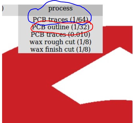
Step-3 Selecting the Process to create traces
Now select the process 1/64 for traces and 1/32 for board outline cutting.
Step-4 Selecting the Process parameters for Traces (1/64 end mill v-bit)
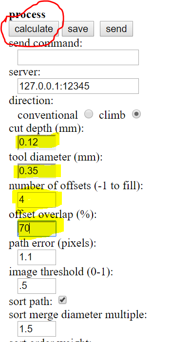
- Cut Depth is how deep you want the tool to cut in your PCB. Generally the cut depth should be equal to the thckness of the Copper Film on the FR4 board that we used.I used 0.12 as it worked best for out makeshift V-bit.
- Tool Diameter is the diamter if the tip of the tool, For tracing we use 1⁄64 and to cut the outer edge we use 1⁄32. Since in our lab we use a V-bit instead of the 1⁄64 bit, by some trial and error TOOL DIAMTER of 0.35mm to .40 worked best for us.
- No. of Offsets is basically the number of passes the tool will take over the surface, for minimum it should be 4 so that traces aren’t short, but if one want’s just the traces and all pther copper to be removed then -1 settings should be used(it takes a long time and noisy)
- Offset Overlap so our tool dia is 0.35, now lets assume it mills one line first, then it goes for the next line, Optimally the difference b/w the two lines should be equal to the tool diameter which is 0.35mm. But to be on the safer side we give a certain overlap percentage so that the cutting head goes over the preiously cut path and makes sure there is no residue left.
- Speed- We left the Default speed i.e 4 mms/sec.
- Direction- Climb should be selected instead of conventional settings it gives best results in climb.
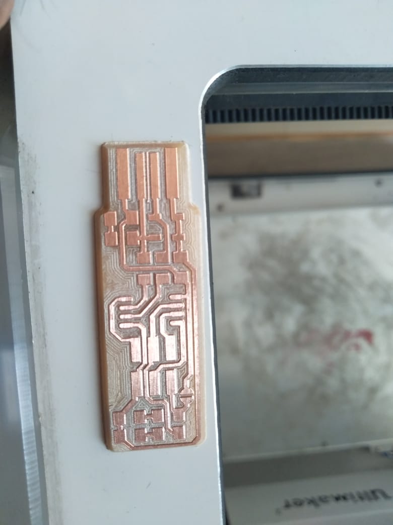
Step-5 Upload the .rml File in VPanel and Mill Board
Software for operating the machine - V panel for SRM-20, you can find more details on our group assignment page. In our lab a setup is made for SRM so I was saved from downloading any kind of software for it as it was already connected to lab’s PC which had the software for it.
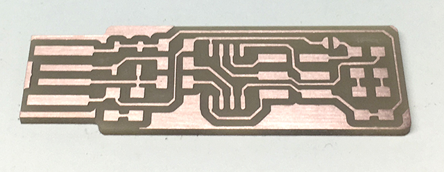
Final Milled Board
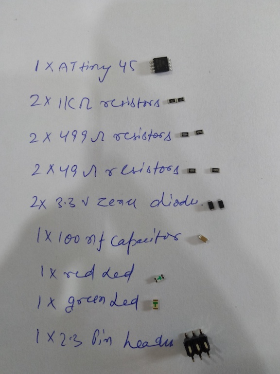
Step-6 Identify Components for Soldering
- Bill of Material for FabISP board
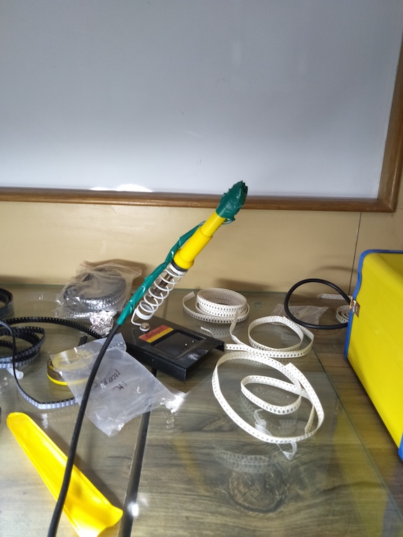
Step-7 Practicing Soldering
Now this has been challenging as this is the first time i actually used any soldering iron. So i started with some practice session on already available unused boards in lab.
-
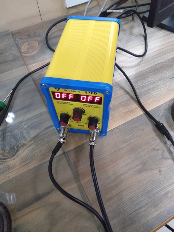
Soldering machine
-
Snapshots of my practice for soldering
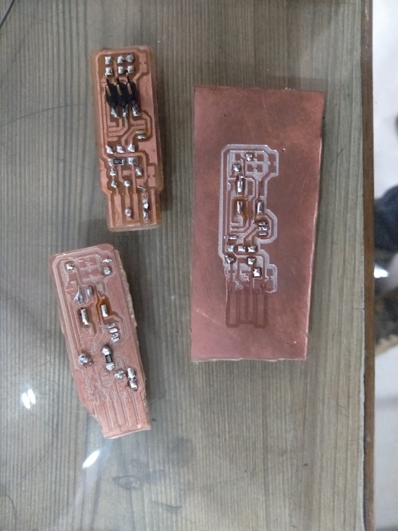
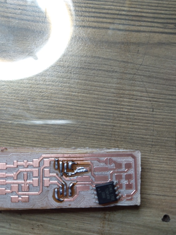
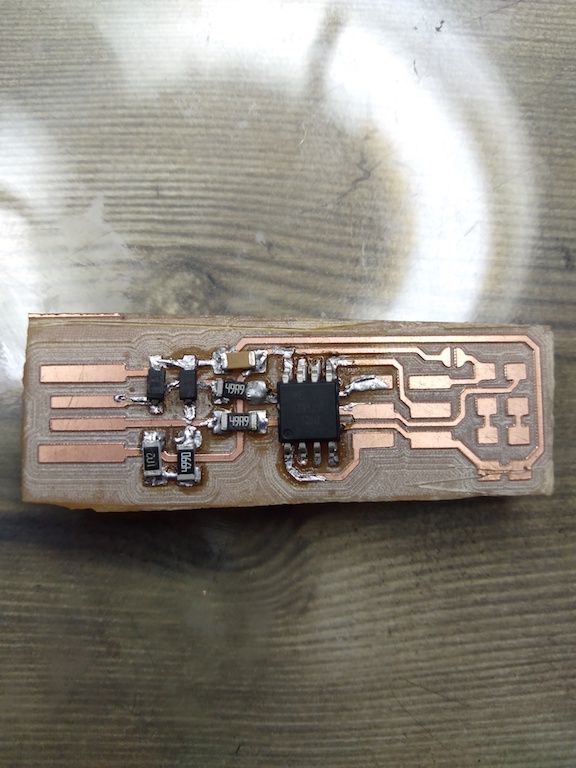
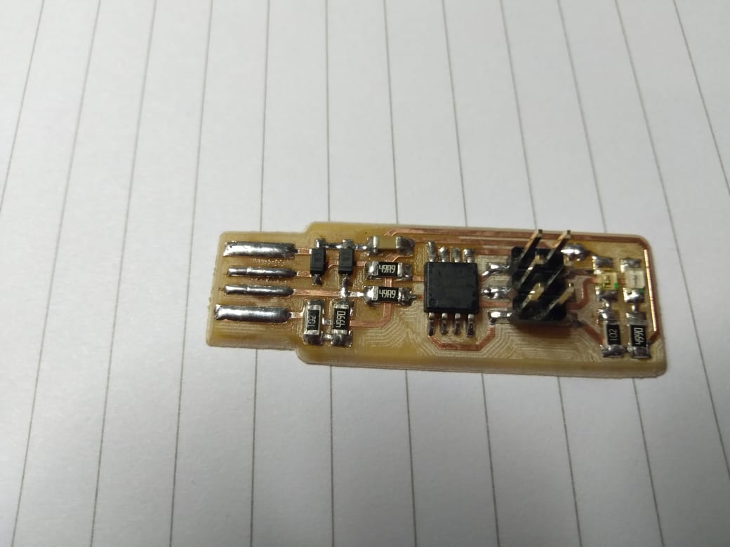
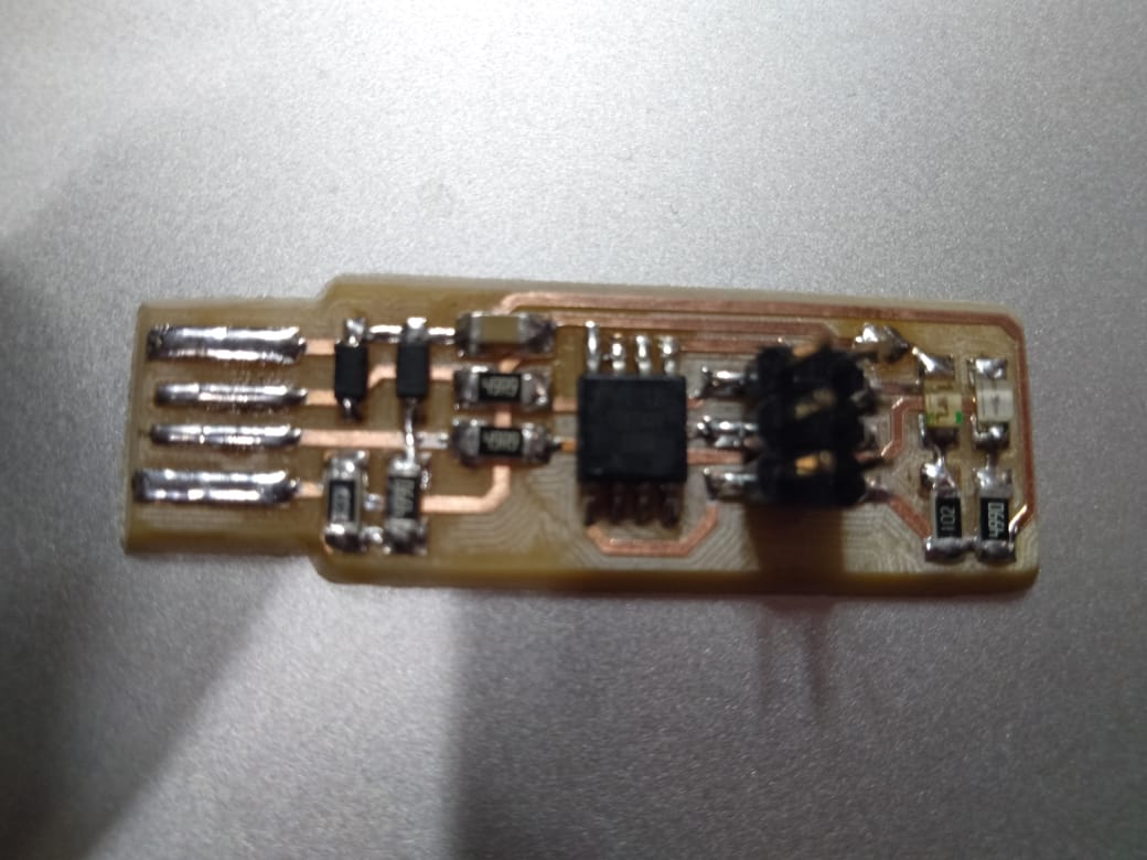
Step-8 Final Soldering
Below are some snapshot after soldering on my final Fab-ISP
Step-9 Programming the Board
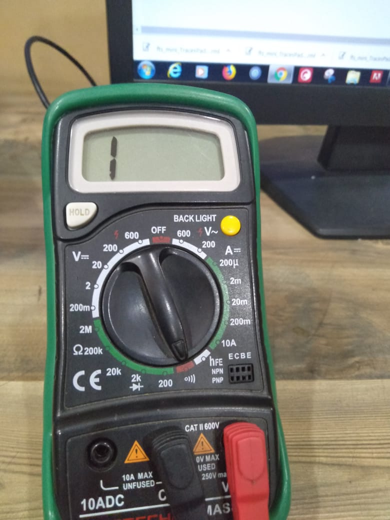
Before programming our instructor spent some time explaining basics of checking the circuit. So i learnt few basics of using multimeter. It has a LED test when you use to connect the positive and negative points of multimeter it gives us a sound. Our instructor Rahul asked us to do a check to ascertain their are no short circuits and components that are suppose to be connected are connected. So we checked resistance value, checked microcontroller pads and basic checks for the overall circuit.
Once my instructor reviewed the PCB i started with programming. All of the instructions are available on Brian Board
- First i installed CrossPack
- Made change in MakeFile and changed the programmer to avrispmkII PROGRAMMER ?= avrispmkII from PROGRAMMER ?= usbtiny
- after that typed make on my terminal
- It created a hex file
- Then i typed make flash on terminal it written the .hex file on my FAB ISP
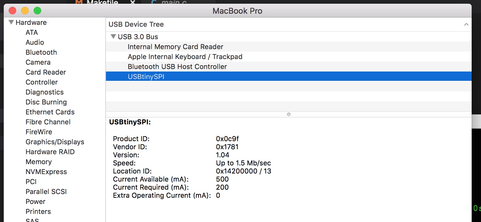
- Once i succesfully programmed the flash memory, it’s time to set the configuration fuses so i connected the FABISP to my laptop and i was able to see its been recognised as USB device
- Once i performed this test i ran make fuses
- Checked that the Fab-ISP is getting detected on my latop
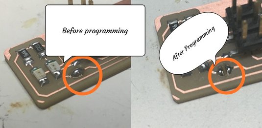
- Desoldering the fuse (image taken from Brian page)
Screenshot of Programming Steps
Rajats-MacBook-Pro-7:fts_firmware_bdm_v1 rajatratewal$ make
avr-gcc -mmcu=attiny45 -Wall -DF_CPU=16500000UL -I. -funsigned-char -funsigned-bitfields -fpack-struct -fshort-enums -Os -Iusbdrv -c main.c -o main.o
main.c:109:13: warning: always_inline function might not be inlinable [-Wattributes]
 static void delay ( void )
             ^
avr-gcc -mmcu=attiny45 -Wall -DF_CPU=16500000UL -I. -funsigned-char -funsigned-bitfields -fpack-struct -fshort-enums -Os -Iusbdrv -c usbdrv/usbdrv.c -o usbdrv/usbdrv.o
avr-gcc -mmcu=attiny45 -Wall -DF_CPU=16500000UL -I. -funsigned-char -funsigned-bitfields -fpack-struct -fshort-enums -Os -Iusbdrv -c usbdrv/oddebug.c -o usbdrv/oddebug.o
avr-gcc -x assembler-with-cpp -mmcu=attiny45 -Wall -DF_CPU=16500000UL -I. -funsigned-char -funsigned-bitfields -fpack-struct -fshort-enums -Os -Iusbdrv -c usbdrv/usbdrvasm.S -o usbdrv/usbdrvasm.o
avr-gcc -mmcu=attiny45 -o fts_firmware.elf main.o usbdrv/usbdrv.o usbdrv/oddebug.o usbdrv/usbdrvasm.o
avr-size -C --mcu=attiny45 fts_firmware.elf
AVR Memory Usage
----------------
Device: attiny45

Program:    2488 bytes (60.7% Full)
(.text + .data + .bootloader)

Data:         75 bytes (29.3% Full)
(.data + .bss + .noinit)


avr-objcopy -j .text -j .data -O ihex fts_firmware.elf fts_firmware.hex
Rajats-MacBook-Pro-7:fts_firmware_bdm_v1 rajatratewal$ make flash
avrdude -p attiny45 -c avrispmkII -P usb -e \
        -U flash:w:fts_firmware.hex

avrdude: AVR device initialized and ready to accept instructions

Reading | ################################################## | 100% 0.00s

avrdude: Device signature = 0x1e9206
avrdude: erasing chip
avrdude: reading input file "fts_firmware.hex"
avrdude: input file fts_firmware.hex auto detected as Intel Hex
avrdude: writing flash (2488 bytes):

Writing | ################################################## | 100% 0.86s

avrdude: 2488 bytes of flash written
avrdude: verifying flash memory against fts_firmware.hex:
avrdude: load data flash data from input file fts_firmware.hex:
avrdude: input file fts_firmware.hex auto detected as Intel Hex
avrdude: input file fts_firmware.hex contains 2488 bytes
avrdude: reading on-chip flash data:

Reading | ################################################## | 100% 0.74s

avrdude: verifying ...
avrdude: 2488 bytes of flash verified

avrdude: safemode: Fuses OK (H:FF, E:DF, L:62)

avrdude done.  Thank you.

Rajats-MacBook-Pro-7:fts_firmware_bdm_v1 rajatratewal$ make fuse
make: *** No rule to make target `fuse'.  Stop.
Rajats-MacBook-Pro-7:fts_firmware_bdm_v1 rajatratewal$ make fuses
avrdude -p attiny45 -c avrispmkII -P usb \
        -U lfuse:w:0xE1:m -U hfuse:w:0xDD:m \
        -U efuse:w:0xFF:m

avrdude: AVR device initialized and ready to accept instructions

Reading | ################################################## | 100% 0.00s

avrdude: Device signature = 0x1e9206
avrdude: reading input file "0xE1"
avrdude: writing lfuse (1 bytes):

Writing | ################################################## | 100% 0.01s

avrdude: 1 bytes of lfuse written
avrdude: verifying lfuse memory against 0xE1:
avrdude: load data lfuse data from input file 0xE1:
avrdude: input file 0xE1 contains 1 bytes
avrdude: reading on-chip lfuse data:

Reading | ################################################## | 100% 0.00s

avrdude: verifying ...
avrdude: 1 bytes of lfuse verified
avrdude: reading input file "0xDD"
avrdude: writing hfuse (1 bytes):

Writing | ################################################## | 100% 0.01s

avrdude: 1 bytes of hfuse written
avrdude: verifying hfuse memory against 0xDD:
avrdude: load data hfuse data from input file 0xDD:
avrdude: input file 0xDD contains 1 bytes
avrdude: reading on-chip hfuse data:

Reading | ################################################## | 100% 0.00s

avrdude: verifying ...
avrdude: 1 bytes of hfuse verified
avrdude: reading input file "0xFF"
avrdude: writing efuse (1 bytes):

Writing | ################################################## | 100% 0.00s

avrdude: 1 bytes of efuse written
avrdude: verifying efuse memory against 0xFF:
avrdude: load data efuse data from input file 0xFF:
avrdude: input file 0xFF contains 1 bytes
avrdude: reading on-chip efuse data:

Reading | ################################################## | 100% 0.00s

avrdude: verifying ...
avrdude: 1 bytes of efuse verified

avrdude: safemode: Fuses OK (H:FF, E:DD, L:E1)

avrdude done.  Thank you.

Rajats-MacBook-Pro-7:fts_firmware_bdm_v1 rajatratewal$
Overall Learning Outcomes for this week
- I learnt about the milling process and how it works
- I was unable to proceed with Vinyl cutter to make the circuit becasue of material unavailability but i think Vinyl cutter is far simpler than Milling machine. I found that milling quality depends on so many factors that getting perfect traces is more of an art then science.
- Soldering need patience and time, but i am happy with my first soldering experience