
Week Nine
Assignment
What I did this week
Reading Microcontroller Data Sheet
I had some experience with programming from my school days. But this was not enough for our works in the fab lab. So I had to work on my basics first. I started reading the Microcontroller data sheet.You can download it from here.By going through the datasheet initially, I really didn't get an idea. I asked my friends help who were good at electronics and they helped me with the basics like the pins, registers, difference between a microcontroller and a microprocessor etc.
What I learned
I started referring previous students documentation and it really helped me with my basics.
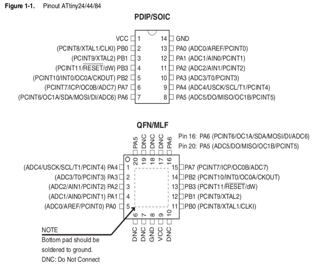 You can see the pins and description of each pin here. The pins are basically divided into different categories like PortB(PB0 to PB3), PortA(PA0 to PA7), VCC and GND.In this PortA and PortB are I/O pins with PortA having some alternate functions like ADC, timer, counter, comparator etc. VCC is the constant supply voltage pin and GND is the ground reset pin.
The next thing I understand from the datasheet is the key features of the MC, the different architectures used, clocks etc. These are as follows
The basic idea that I was able to make out is that RISC architecture is a design strategy in which we can use simplified instruction sets whereas in CISC(Complex Instruction Set Computer) the number of instructions per program can be reduced by embedding the number of operations in a single instruction, thereby making the instructions more complex but saves you more memory space. Read more about it here .
This means that our MC can take upto 20000000 instruction per second
The maximum size of the programme that can be flashed into our MC is 4kb.
Other Details
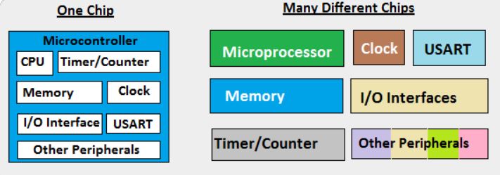
The best way to understand a microcontroller is to compare it with our PC. A microcontroller is like a mini pc with the processor , RAM, I/O features etc integrated into a single component. Whereas on our PC we have separate components for each of this process. But the processing capacity and versatility of the microcontrollers are really low compared to our PC as they can only do a single task at a time.
These are the pins that we use to programme our MC. We have MISO(Master Input Slave Output), MOSI(Master Output Slave Input) and RESET to programme our MC. The output from the MC after flashing is done through MISO and input(programmes) to the MC is sent through MOSI. We can restart the MC by setting the reset pin to ground. So it is used to add a Reset button to our MC.
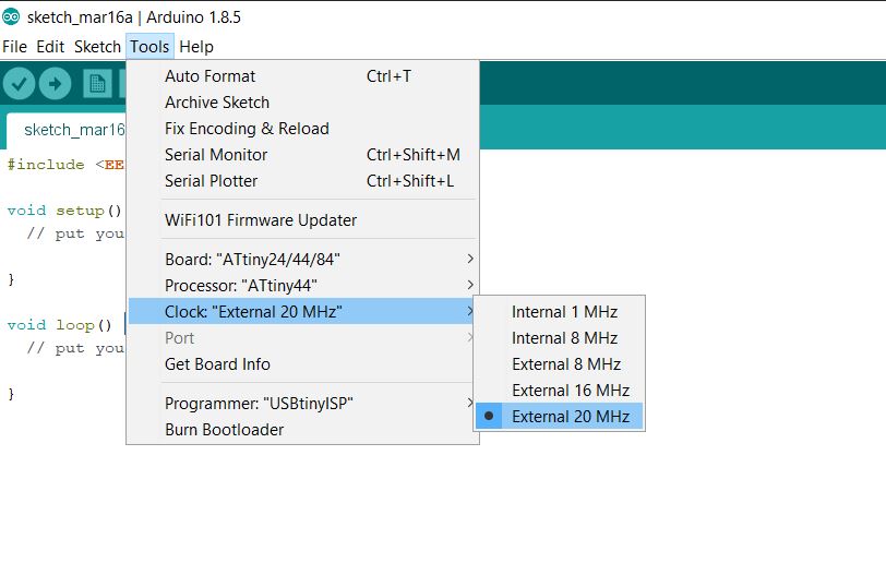
Clock refers to the frequency in which an MC works. Our MC has an internal clock of 1 Mhz. But we have also connected a 20 Mhz external clock to this to increase its accuracy.
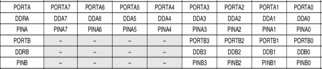
In our MC, Ports are represented by their internal registers so that we can assign an input or output value to it.In our MC the PA ports have 8 pins with 1-bit data each and PB ports have 4 pins with 1-bit data each. We can tweak these values to set each pin as Input and Output.Each pin specification details are as below.
Programming
There are different ways to programme the Hello-Echo board. I am planning to try Arduino IDE and Atmel Studio . Programming Arduino IDE is somewhat simpler since we are using a much simpler language and the commands are much easier to understand. In Atmel studio, we are using AVR C which is a little bit complicated compared to Arduino IDE since the commands are a bit confusing and there are some logic we have study before trying AVR C. Since I was from a mechanical background and I didn't have any prior knowledge in embedded programming I thought to go with the simpler one first.
Arduino IDE
Before starting programming I had to set up my Arduino IDE software. I downloaded the software from here .
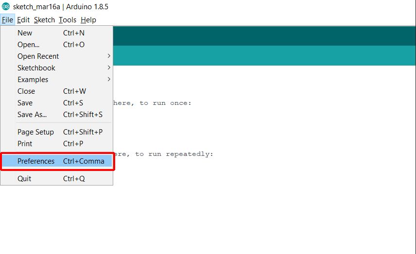
By default, the software doesn't have the Attiny44 chip libraries. SO we have to add them externally. For this 1st download and install the Arduino IDE software. Then go to file >> preferences which will open a window.
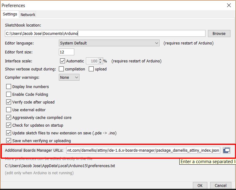
In the Preferences window go to the Board manger URL and change it and click Ok. I used the following URL
https://raw.githubusercontent.com/damellis/attiny/ide-1.6.x-boards manager/package_damellis_attiny_index.json
Now open the board manager by going to Tools>>Board>>Board Manager
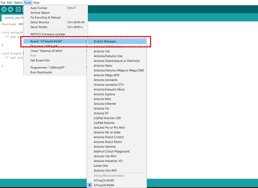
Type attiny in the search bar of the window and select our library file. CLick on install button to install those files.
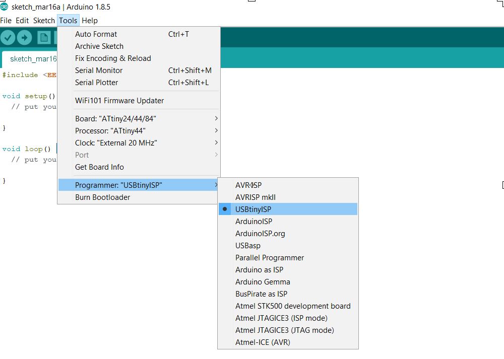
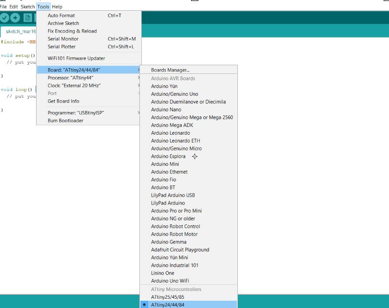
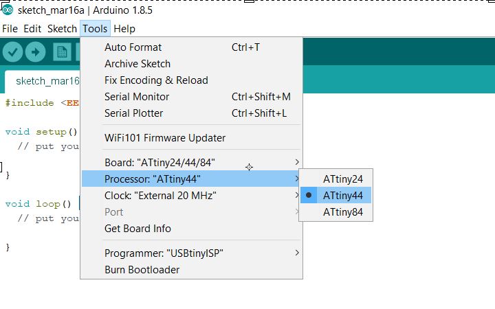
Now, select appropriate clock programmer and board in the software to start programming.
Now connect the Hello-Echo board your pc using the Fab ISP. I wrote a simple program to blink the LED.
              void setup()
                {
                  pinMode(PA2,OUTPUT);

                }
              void loop()
                {
                  digitalWrite(PA2,HIGH);
                  delay(1000);
                  digitalWrite(PA2,LOW);
                  delay(1000);
                }
On clicking the upload button I recieved a error message that Usb tiny could not be found
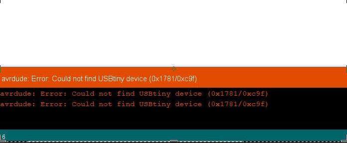
Later found that it was a problem with drivers and I had to install the drivers for windows for the same.I downloaded the adafruit Attiny44 driver from here.
After installing the drivers I could easily flash the programme to the board.
After this, I tried a different program with the push button.
                void setup()
                  {
                    pinMode(PA2,OUTPUT);
                    pinMode(PA3,INPUT);

                  }
                void loop()
                  {
                    if(digitalRead(PA3) == HIGH)
                      {
                        digitalWrite(PA2,HIGH);
                      }
                     else
                      {
                        digitalWrite(PA2,LOW);
                      }
                    }
Atmel Studio
In Atmel Studio we use Avr C language which is a bit difficult compared to the Arduino. Here we got to have a thorough knowledge of Microcontroller registers, logic circuits and things like that. This is where the datasheets could help us.
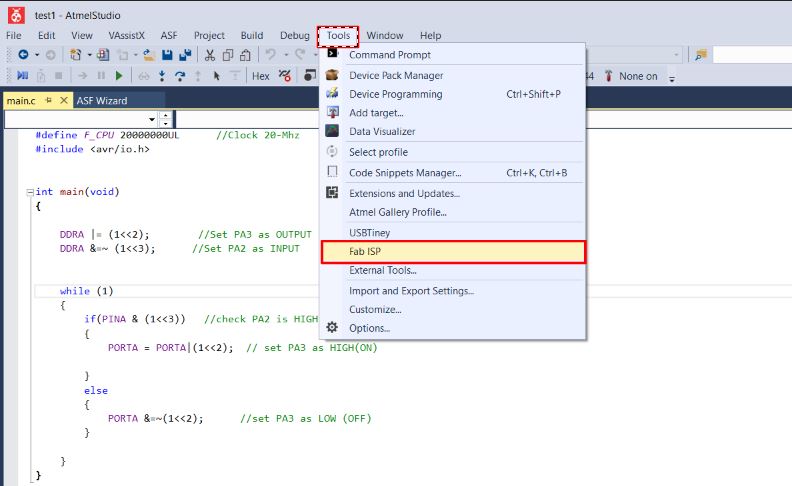
To start programming our board using Fab ISP we have to first configure our ATmel studio.
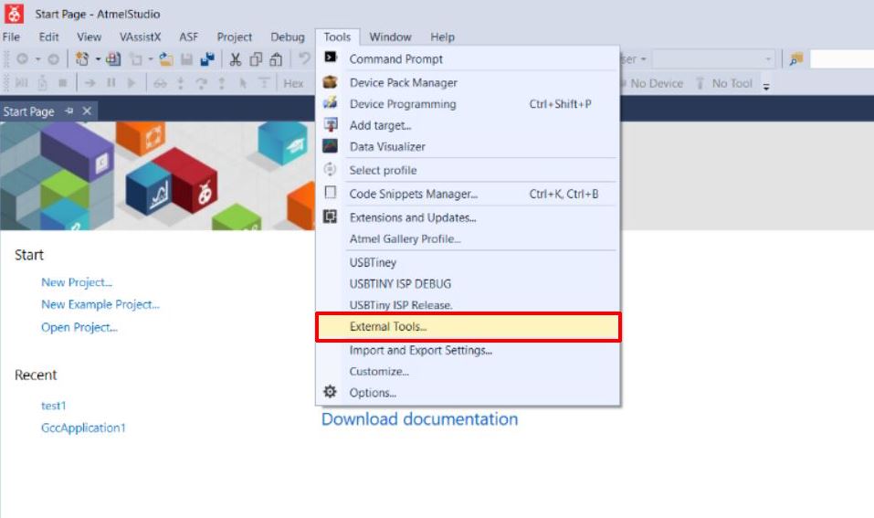
Before this first download your Atmel studio from here. Now you have to install the Avrdude which you can download from this link.Now open Atmel studio and click on the Tools tab.Click on the External tools in the pop up window.
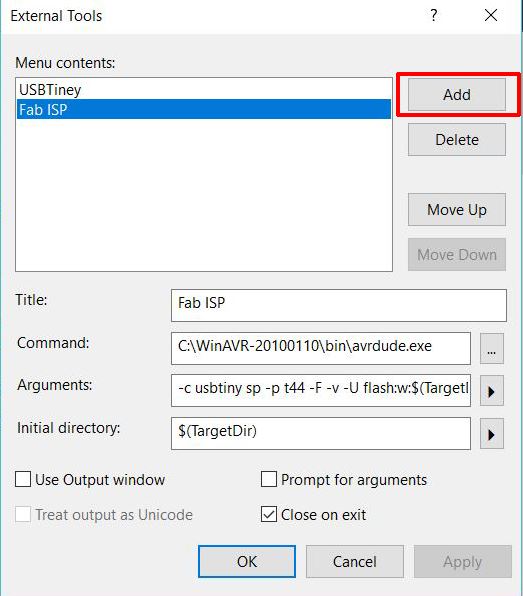
Click on the Add button to add our fab ISP. And then fill the respective coloumns as given below.
Command: C:\WinAVR-20100110\bin\avrdude.exe
Arguments:
-c usbtiny sp -p t44 -F -v -U flash:w:$(TargetDir)$(TargetName).hex:i
Initial Directory:
$(TargetDir)
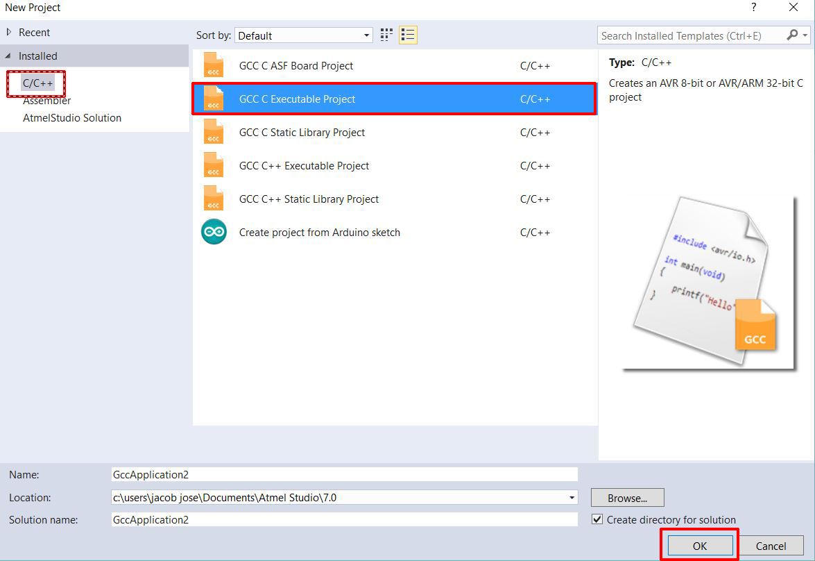
Now to start a new project goto File>>New>>Project
In the window select C/C++ as language and select the second one from the selected list
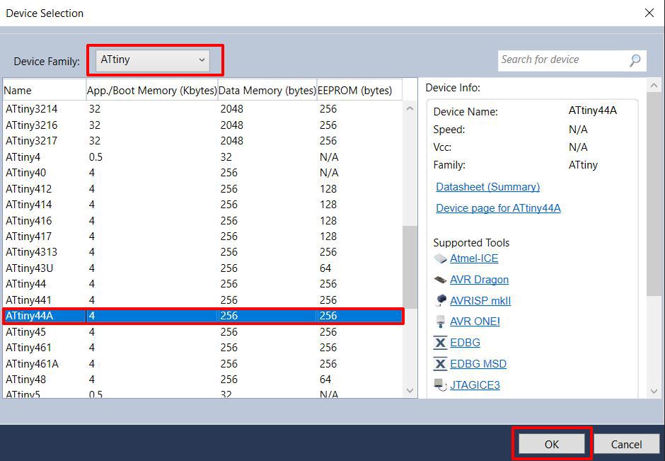
In the in the next window window select Attiny as the device family and select Attiny44A from it and press ok.
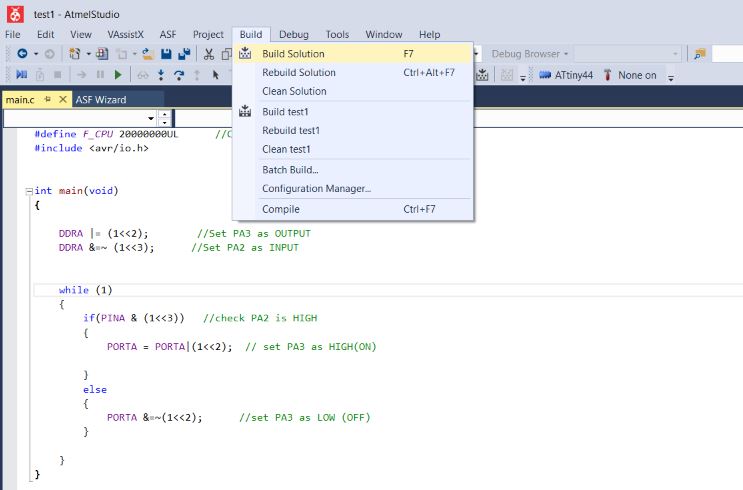
#define F_CPU 20000000UL      //Clock 20-Mhz
#include


int main(void)
{

	DDRA |= (1<<2);        //Set PA3 as OUTPUT
	DDRA &=~ (1<<3);      //Set PA2 as INPUT


	while (1)
	{
		if(PINA & (1<<3))   //check PA2 is HIGH
		{
			PORTA = PORTA|(1<<2);  // set PA3 as HIGH(ON)

		}
		else
		{
			PORTA &=~(1<<2);      //set PA3 as LOW (OFF)
		}

	}
}
Group Assignment
This weeks group assignment was to compare the performance and development workflows for other architectures. We mainly focused on the ARM ARCHITECTURE and STM 32 and you can fing more detailed doccumentation about it in Salman's doccumentation.
