
Week Eleven
Assignment
What I did
Introduction
This week is all about different sensors and input devices. These sensors can be used to measure different quantities ie; Temperature, Pressure, Light, Movement etc. The sensor outputs are normally analog values and we have to convert them to digital values and analyze them using appropriate microcontroller circuits.
I am planning to make a circuit which can further help me during my final project. Since I am making a smart speaker I need a Mic to interact with the speaker. So the idea was to design a circuit with a MEMS Mic to read the sound values.
Basics
The application of MEMS (microelectro-mechanical systems) technology to microphones has led to the development of small microphones with very high performance. MEMS microphones offer high SNR, low power consumption, good sensitivity, and are available in very small packages that are fully compatible with surface mount assembly processes. MEMS microphones exhibit almost no change in performance after reflow soldering and have excellent temperature characteristics.Changes in air pressure created by sound waves cause the thin membrane to flex while the thicker backplate remains stationary as the air moves through its perforations. The movement of the membrane creates a change in the amount of capacitance between the membrane and the backplate, which is translated into an electrical signal by the ASIC.(SOURCE:https://www.edn.com/design/analog/4430264/Basic-principles-of-MEMS-microphones-)
To know more about MEMS microphone read this link.
Design
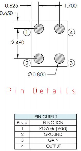
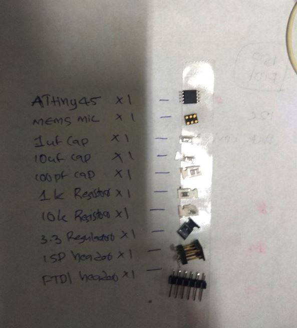
I started by referring Niels board and studiying its components.Neil used a I then went trough the MEMS analogue mic datasheet and Sisonic Design guide to know about the functions of each components in Niels board.
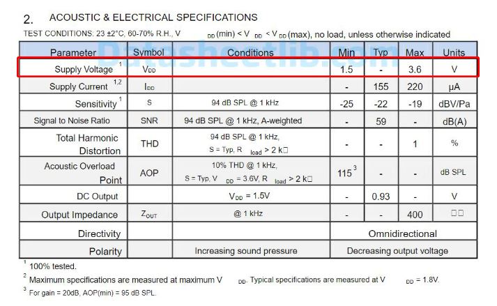
Since the supply voltage of the Mic is about 3.5 v we have to use a voltage regulator.
To know more about other components and Gain control refer the previous design guide.
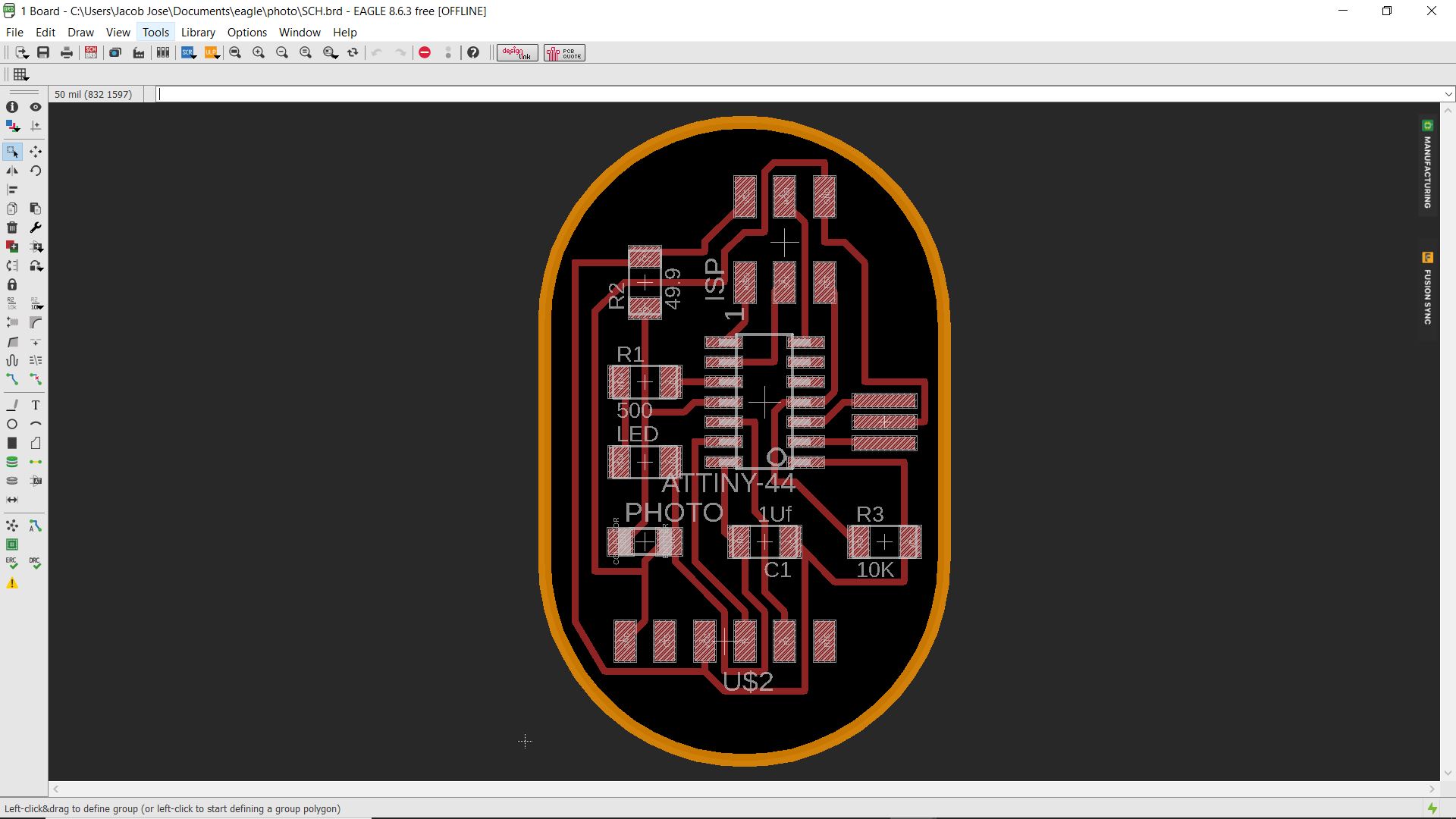
I fixed the components and started designing in Eagle.
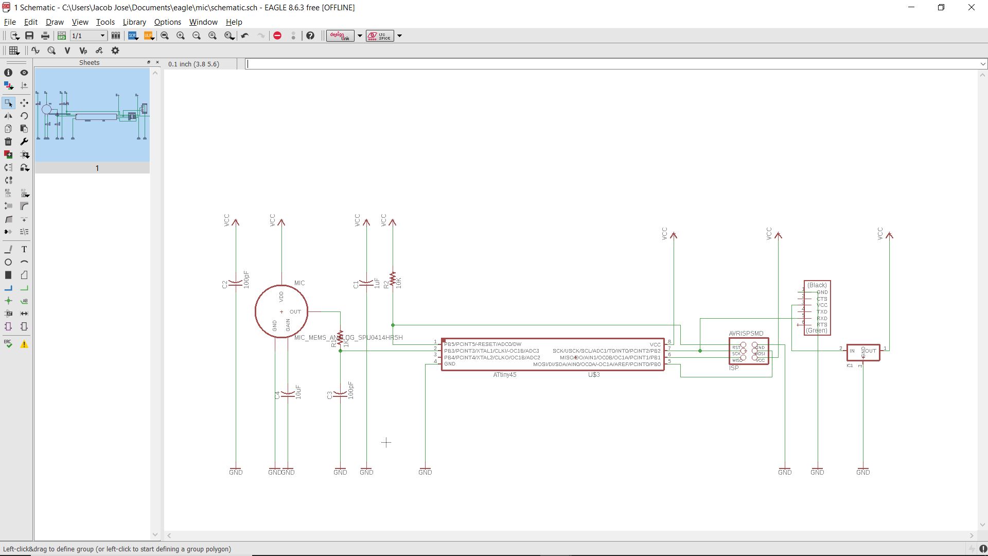
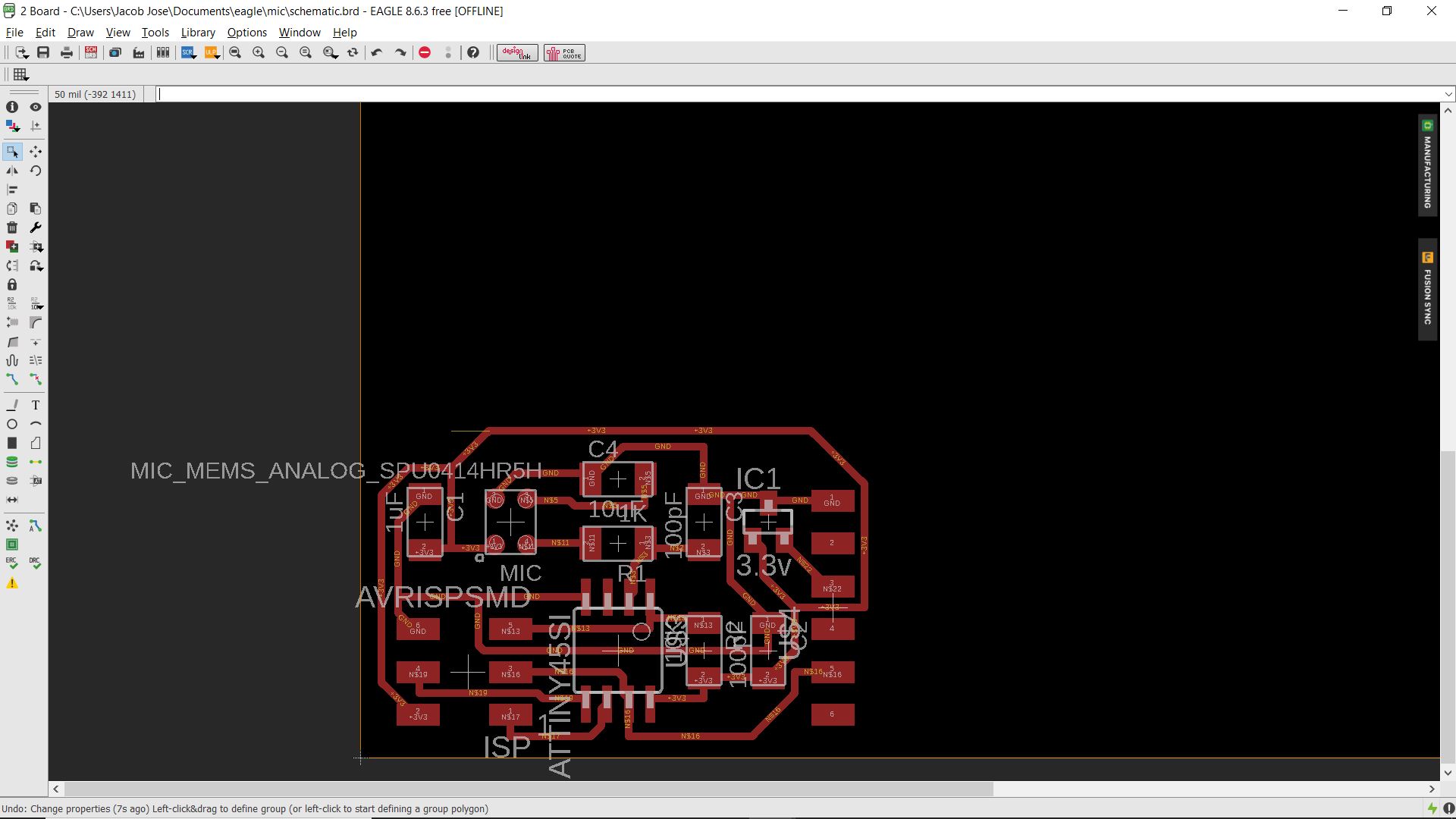
Download all the Design files including the cut and trace png here.
Milling Pcb
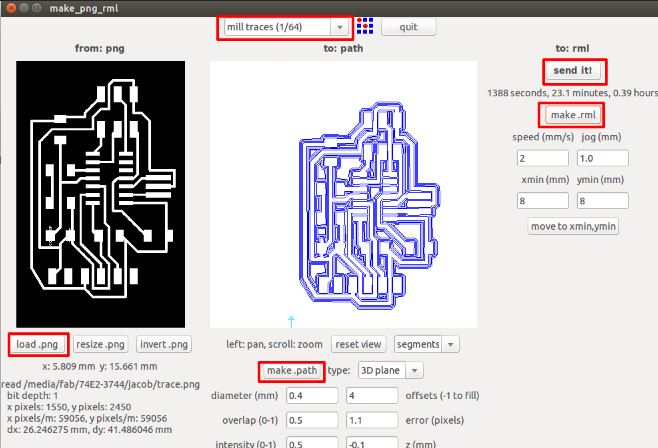
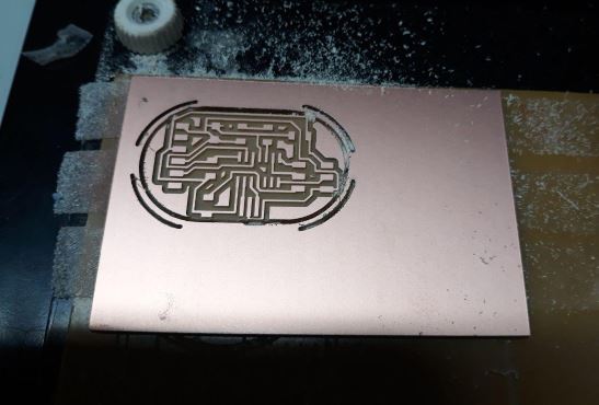
I used the Trace and cut png to mill the board in our Modella MDX 20 milling machine.
Problems
I realised a huge mistake once when I started soldering the components.The mic that I used in my design and the MEMS Mic that we had in our inventory was completely different.It was a fault from my part as I should have checked tthe components beforehand. I actually checked the mic before designing and it looked similar to the one in Neils board but I never checked the labels and details .
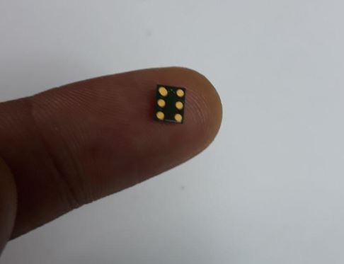
The Mic we had in our lab was a digital MEMS SPM1437HM4H-B. See its datasheets here.
The Mic in Neils board had only 4 pads while the one in our inventory had 6 pads. So it was really hard to incorporate this mic to this existing design.
The next problem was soldering the MEMS Mic as it can be attached to the board using a method called Reverse Soldering in which we use a hot air gun to fuse the lead below the components. But our hot gun was out of service and I had to drop my plan and to start designing something else.
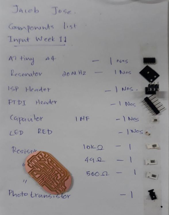
Photo Transistor
Since my plan to make the mic didnt work as planned I thought to use a light sensor this time as it had a fairly simpler design.We have Phototransistor in our lab which will serve my purpose.
Phototransistor
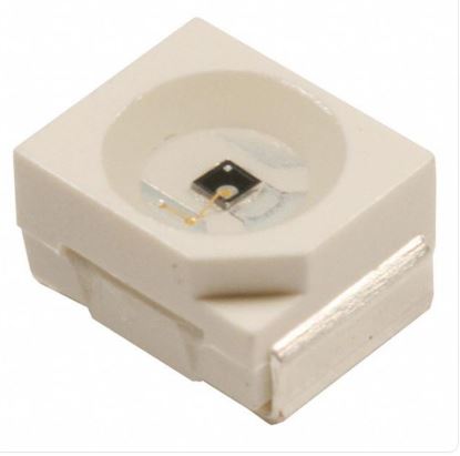
The phototransistor is a device that is able to sense light levels and alter the current flowing between emitter and collector according to the level of light it receives.The photo transistor operates because light striking the semiconductor frees electronics / holes and causes current to flow in the base region.For more details about the working of phototransistor refer this link.
I first refered Niels board to know about the components
Design
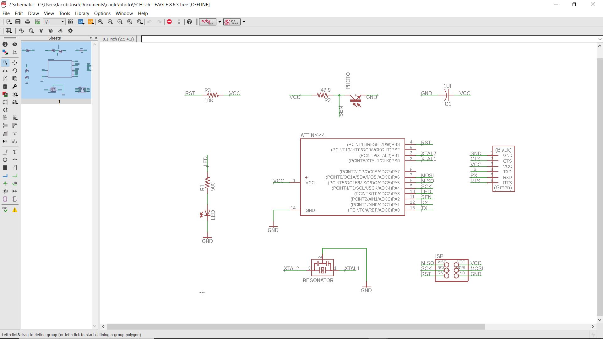
I started designing the board in eagle.
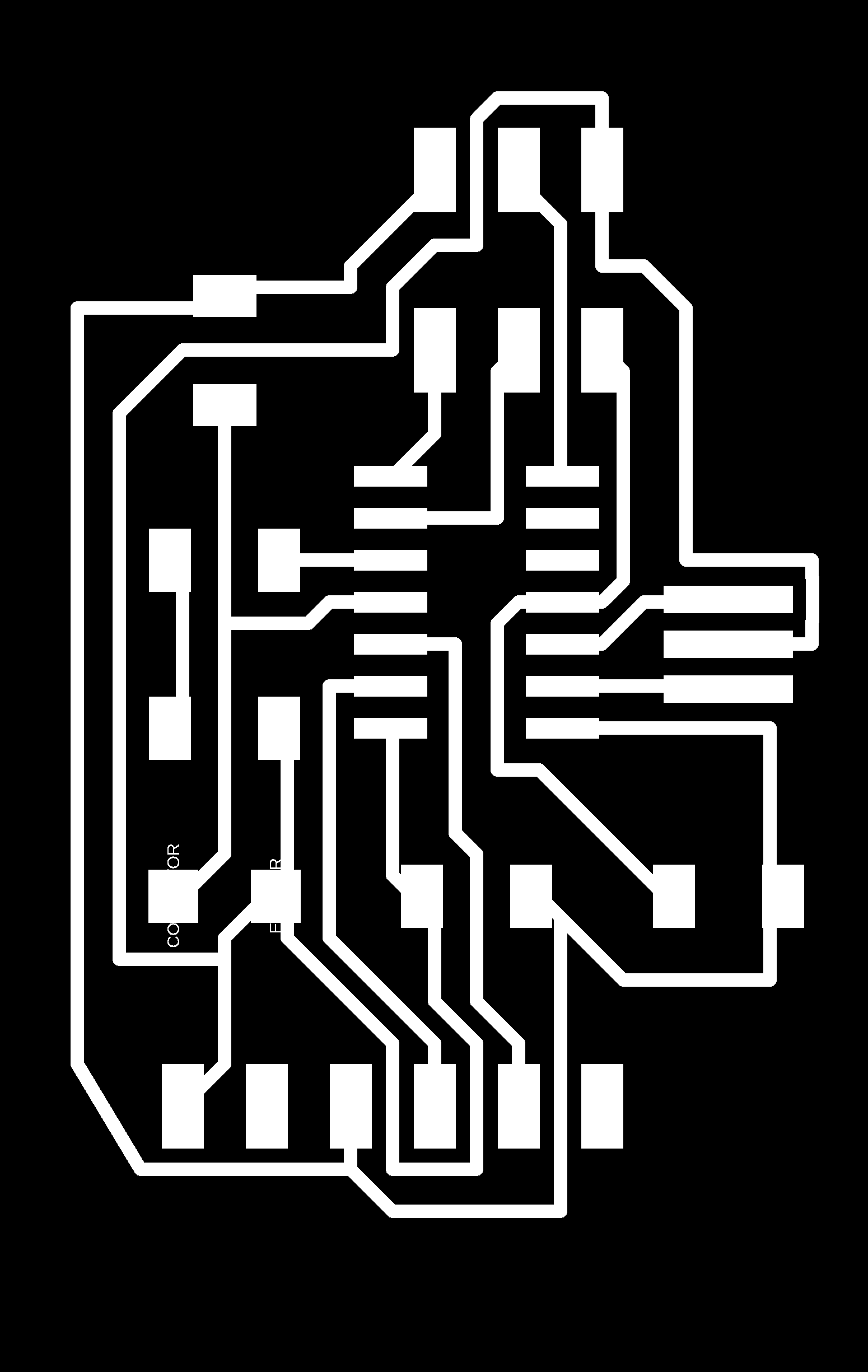

Download the design files including the cut and trace PNG here.
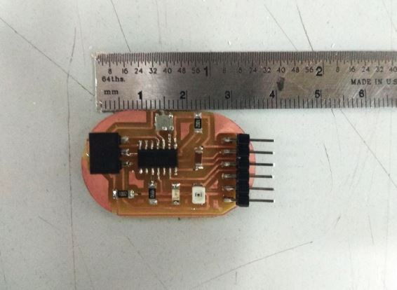
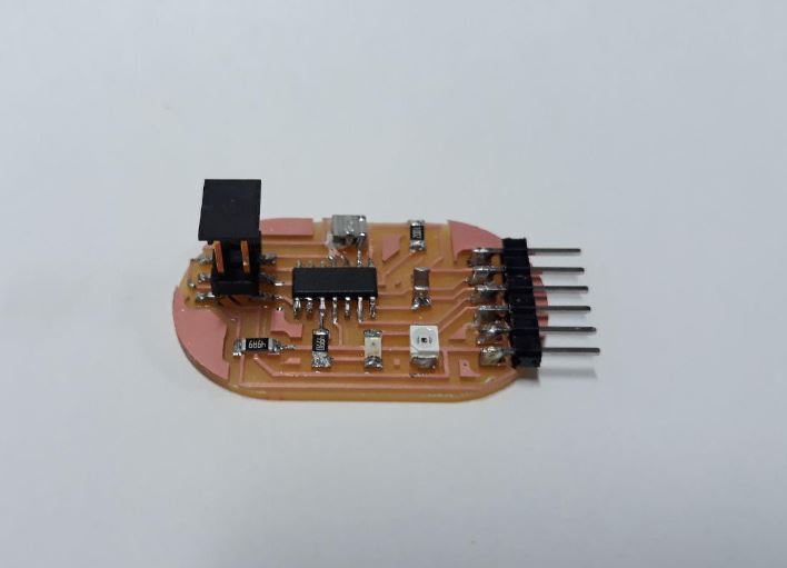
Milling PCB
I used the Modella MDX20 milling machine for milling my PCB I followed the same procedure like I have mentioned in my previous assignments.

Programming the Board
I started programming the board using Arduino IDE. I referred this doccumentation to start with my programming.
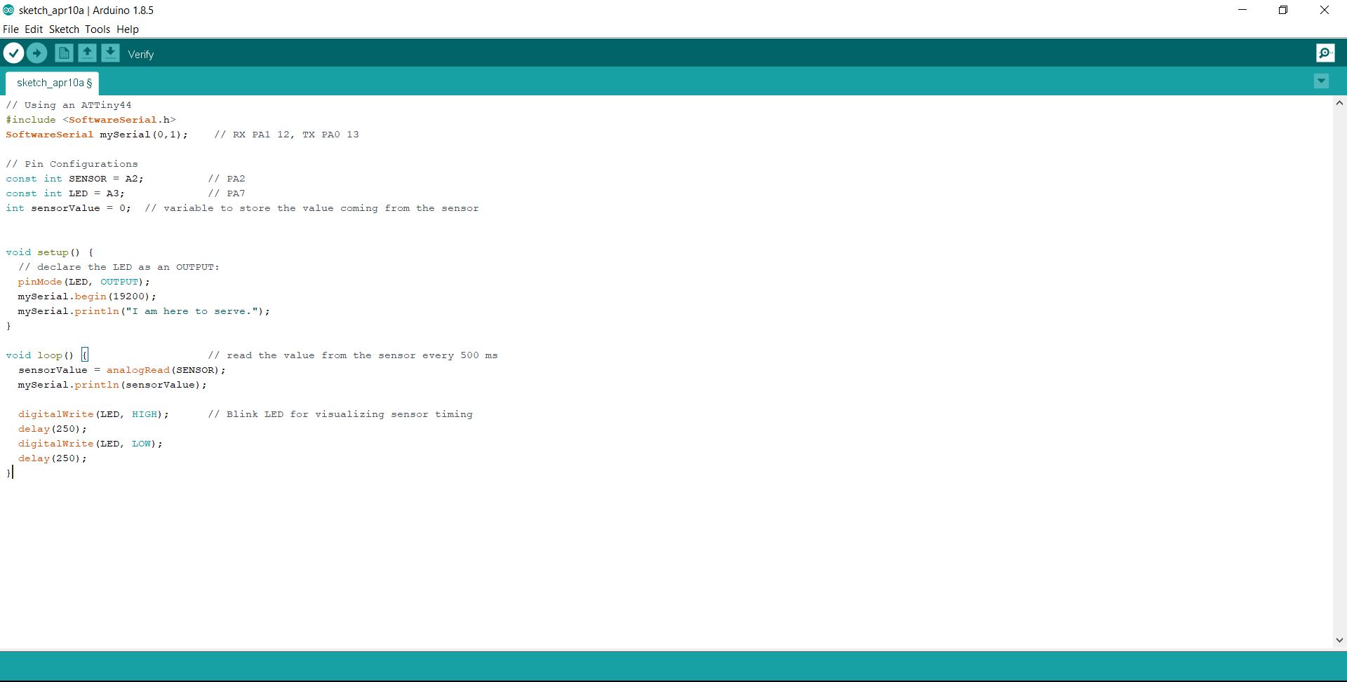
		#include
		SoftwareSerial mySerial(0,1);

		// Pin Configurations
		const int SENSOR = A2;
		const int LED = A3;
		int sensorValue = 0;


		void setup() {
		// declare the LED as an OUTPUT:
		pinMode(LED, OUTPUT);
		mySerial.begin(19200);
		mySerial.println("I am here to serve.");
		}

		void loop() {
		sensorValue = analogRead(SENSOR);
		mySerial.println(sensorValue);

		digitalWrite(LED, HIGH);
		delay(250);
		digitalWrite(LED, LOW);
		delay(250);
		}
The sensor was detecting the values only when a flashlight was used. I found out that it was a problem with the resistor I used with the phototransistor. I used a 49.9 ohm reistor which was a fairly low value. Actually I should have used a 49.9K ohm resistance instead. So I refered niels board again and he used a 10 Kohm resistor. I replaced my 49.9 ohm resistor with the 10 Kohm ones and tested it again.
You can see three sensor conditions : No light condition, Normal light condition and Flash light condition.
Alternate Program
I made small changes in my program inorder to blink the LED when a shadow casts into the phototransistor or the light reduces.See the code below.
		#include
		SoftwareSerial mySerial(0,1);


		const int SENSOR = A2;
		const int LED = A3;
		int sensorValue = 0;

		void setup() {

		pinMode(LED, OUTPUT);
		mySerial.begin(19200);
		mySerial.println("I am here to serve.");
		}

		void loop() {
		sensorValue = analogRead(SENSOR);
		mySerial.println(sensorValue);
		if(sensorValue>900)
			{digitalWrite(LED, HIGH);}
		else
			{digitalWrite(LED, LOW);}

		}
Group Assignment
In the group Assignmnet we need measure the analog levels and digital signals in an input device and display in to the DSO.but in our lab we have UniSource DS-1100 Digital Storage Oscilloscope but it doesn't have an ASCII text / binary decode function (datasheet :- http://www.testequipmentdepot.com/unisource/pdf/ds-1065_1100_1200_datasheet.pdf)
