
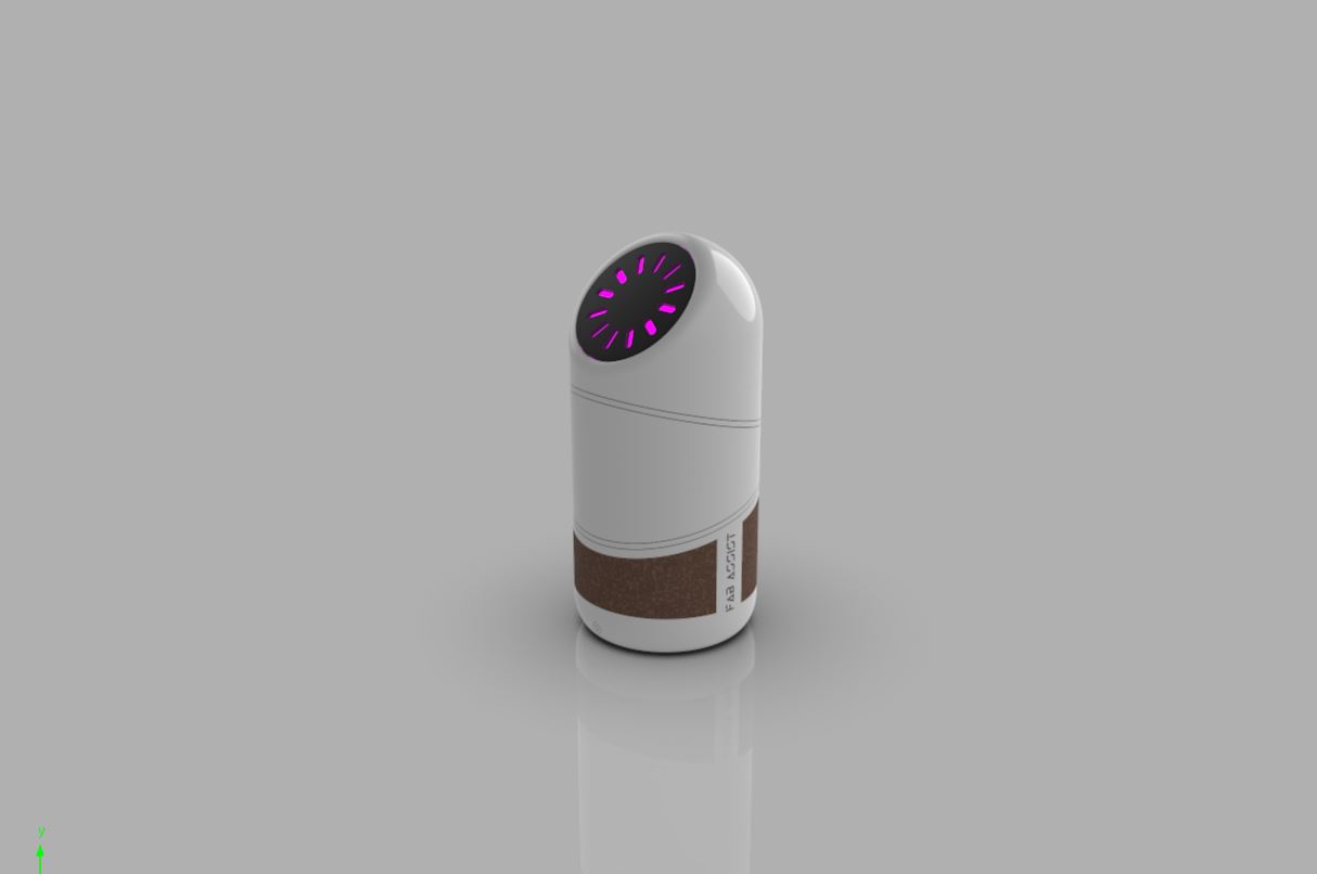
Smart Speaker
My idea is to develop assistant based on google api. I want it to act like a smart speaker with some dancing and lighting features.The brain for processing the audio output will be a raspberry pi zero. I'll be adding custom boards for servo movement and light features.
My project will consist of different processes that I've learned through through this course.
This can be called a Fab Assist in which the raspberry pi will be communicating with other boards using serial communication.I'll be using the google API to function it like google home.
Ideation Stage
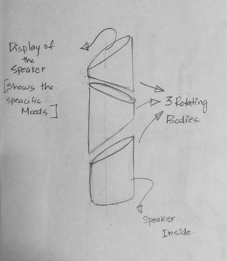
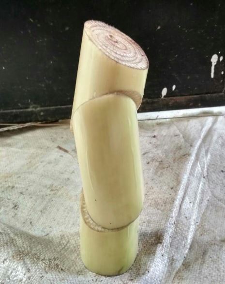
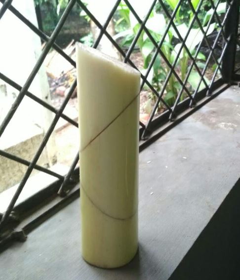
I went through different ideation sketching to get a satisfiying shape for my product. The simple idea was to have a single cylindrical body splitted into 3 bodies on three different non-parllel planes so that when they rotate about that plane we will get some sort of a dancing movement.
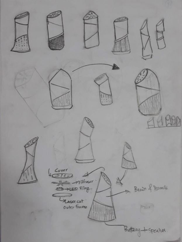
Shape study
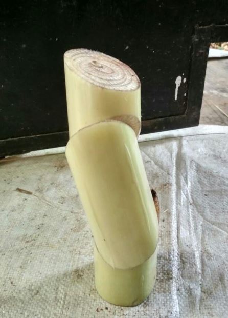
I wanted to know about the forms of the design and how well the shapes will work. So I went for a small alternative 'banana stems' cause it has a nice cylindrical shape, it was readily available and easy to modify the shape.
Electronics
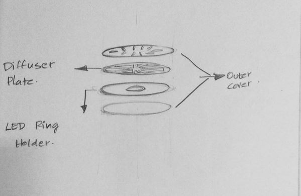
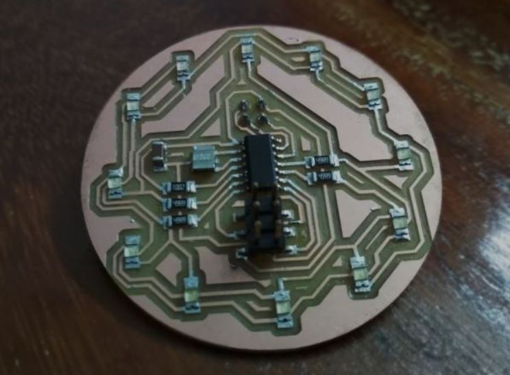
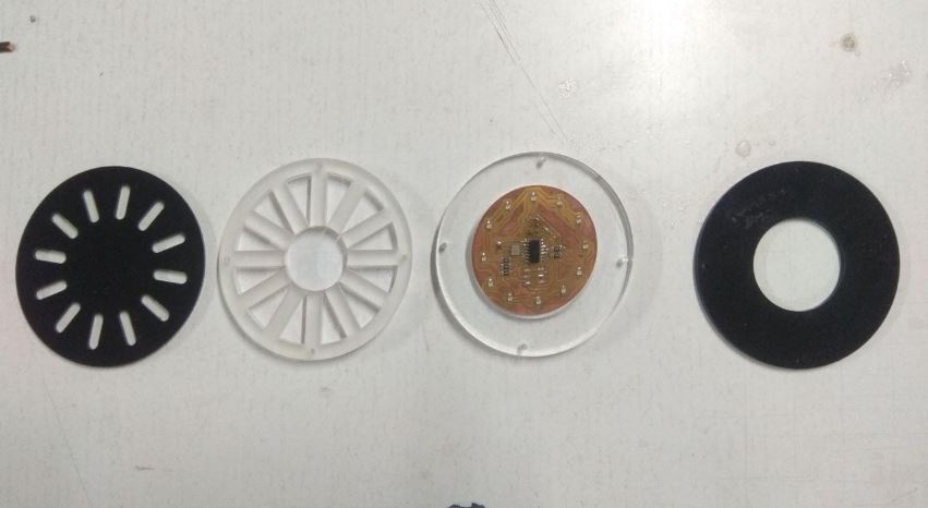
LED Ring
I've already designed my LED ring in the Networking week.
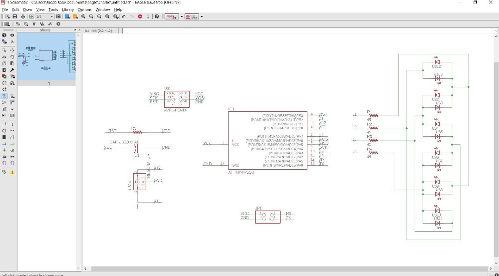
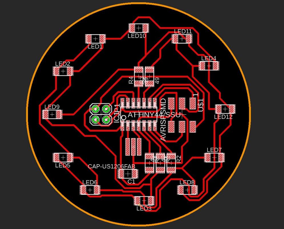
Download the design files here.
Running a simple test program for a running LED in arduino IDE.
		#include
		#define NUMBER_OF_PINS 4

		byte pins[] = {8,7,3,2};
		Charlieplex charlieplex = Charlieplex(pins , NUMBER_OF_PINS);

		charliePin led1 = { 0 , 1 };
		charliePin led2 = { 1 , 0 };
		charliePin led3 = { 0 , 2 };
		charliePin led4 = { 2 , 0 };
		charliePin led5 = { 1 , 2 };
		charliePin led6 = { 2 , 1 };
		charliePin led7 = { 1 , 3 };
		charliePin led8 = { 3 , 1 };
		charliePin led9 = { 0 , 3 };
		charliePin led10 = { 3 , 0 };
		charliePin led11 = { 2 , 3 };
		charliePin led12 = { 3 , 2 };
		void setup(){
					}
		void loop(){
				charlieplex.charlieWrite(led10,HIGH);
				delay(100);
				charlieplex.clear();
				charlieplex.charlieWrite(led11,HIGH);
				delay(100);
				charlieplex.clear();
				charlieplex.charlieWrite(led4,HIGH);
				delay(100);
				charlieplex.clear();
				charlieplex.charlieWrite(led12,HIGH);
				delay(100);
				charlieplex.clear();
				charlieplex.charlieWrite(led7,HIGH);
				delay(100);
				charlieplex.clear();
				charlieplex.charlieWrite(led8,HIGH);
				delay(100);
				charlieplex.clear();
				charlieplex.charlieWrite(led3,HIGH);
				delay(100);
				charlieplex.clear();
				charlieplex.charlieWrite(led6,HIGH);
				delay(100);
				charlieplex.clear();
				charlieplex.charlieWrite(led5,HIGH);
				delay(100);
				charlieplex.clear();
				charlieplex.charlieWrite(led9,HIGH);
				delay(100);
				charlieplex.clear();
				charlieplex.charlieWrite(led2,HIGH);
				delay(100);
				charlieplex.clear();
				charlieplex.charlieWrite(led1,HIGH);
				delay(100);
				charlieplex.clear();
				}
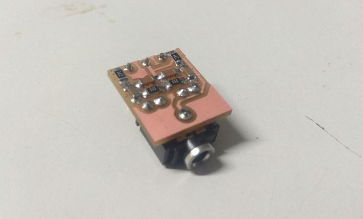
Audio Output
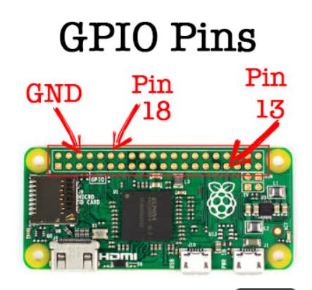
Raspberry pi zero doesn't has an in built audio.So. I'll have to add a audio filter circuit to filter out the audio output through the GPIO pins and send it out through the 3.5mm audio jack.I went through this page to get an idea about this.
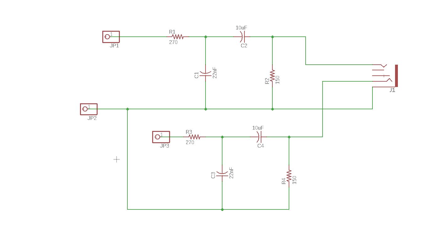
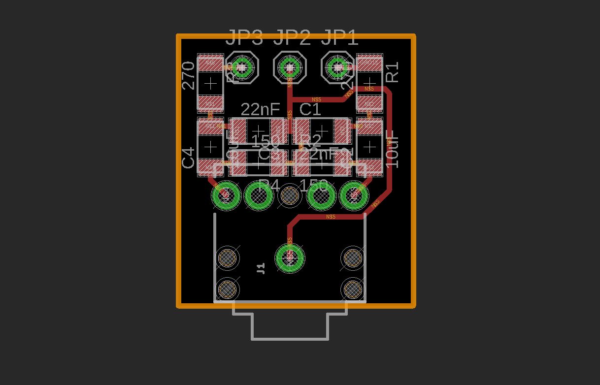
Download the design files here.
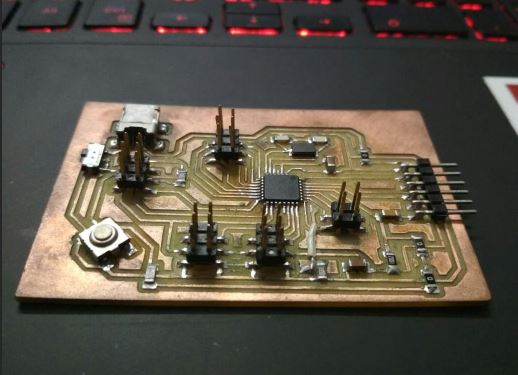
Servo and LED driver
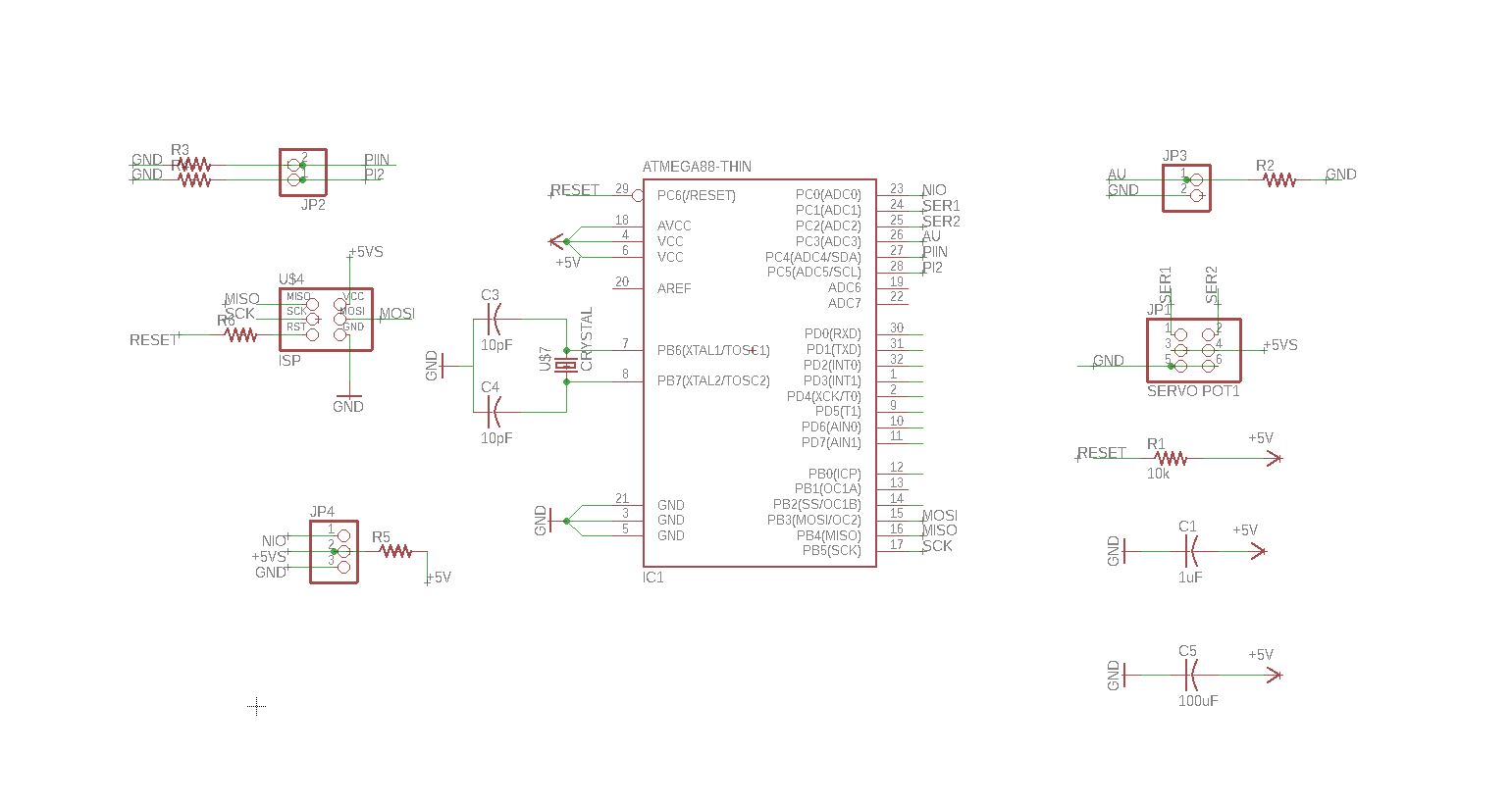
At first I needed to make some kind of an arduino clone to drive my servos and led ring. So I started by taking an existing design called Danduino based on atmega 328p chipset designed by a guy called dan chen since this one used only the components in our fab inventory so I picked this one over the shashta kit. I will be first checking this design and later I will removing all the unwanted pins and redesign the board for my purpose.
I followed the steps mentioned by him and he even included the steps to set up the Arduino IDE for
atmega 328P
I wrote a code to sweep two servos in different angles. One in 180degree and other 90 degres.
#include

Servo myservo1;

Servo myservo2;

int pos_1 = 0;
int pos_2 = 0;

void setup() {
myservo1.attach(A1);
myservo2.attach(A2);

}

void loop() {


for (pos_1 = 0; pos_1 <= 180; pos_1 += 1)
	 {
	myservo1.write(pos_1);              // goes from 0 degrees to 180 degrees
	delay(15);
	}
	for (pos_1 = 180; pos_1 >= 0; pos_1 -= 1)
	{
	myservo1.write(pos_1);              // goes from 180 degrees to 0 degrees
	delay(15);
	}


	for (pos_2 = 0; pos_2 <= 90; pos_2 += 1)
	{
	myservo2.write(pos_2);        		// goes from 0 degrees to 90 degrees
	delay(15);
	}
	for (pos_2 = 90; pos_2 >= 0; pos_2 -= 1)
	{
		myservo2.write(pos_2);         	// goes from 90 degrees to 0 degrees
		delay(15);
	}
	}
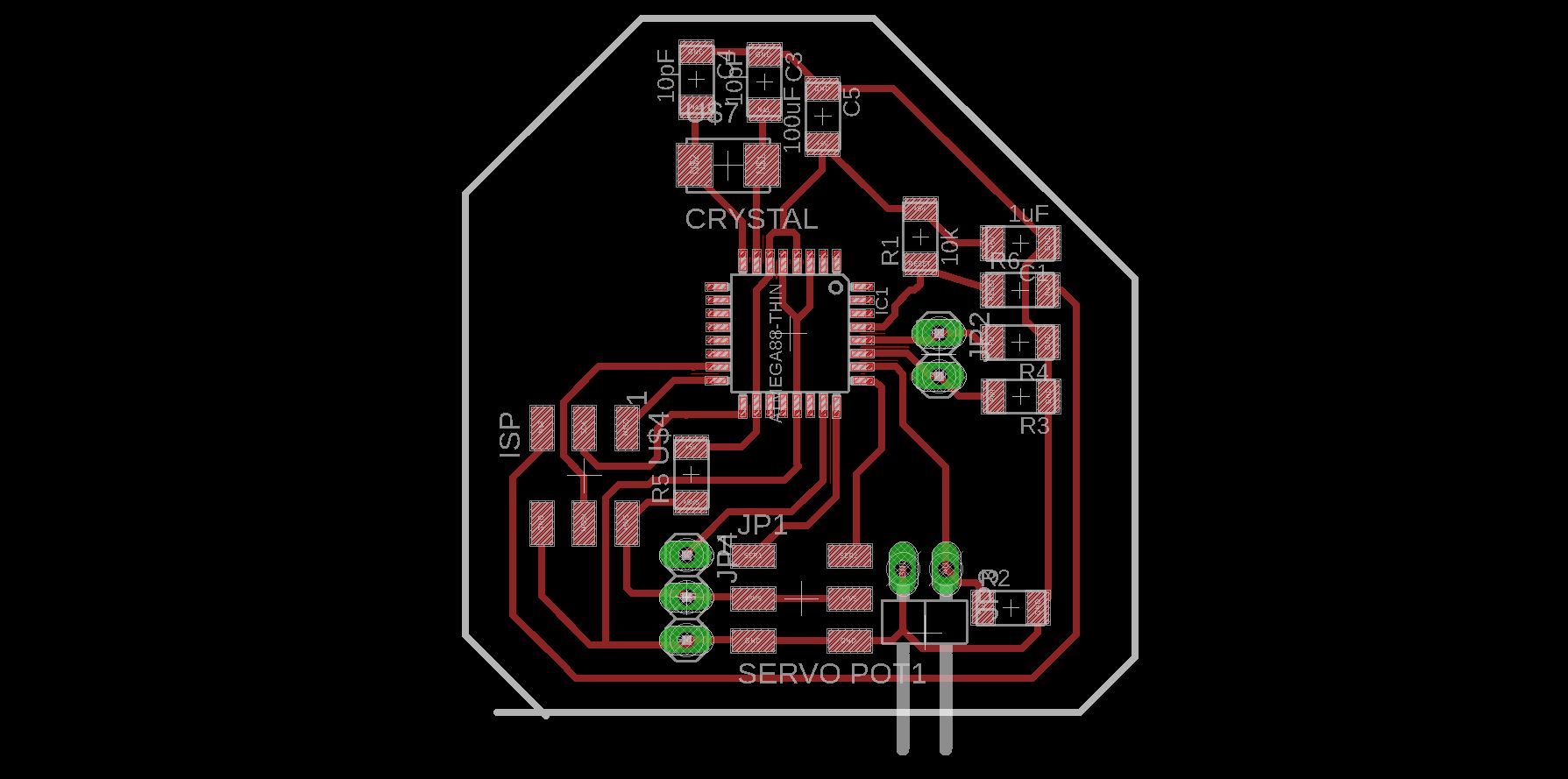
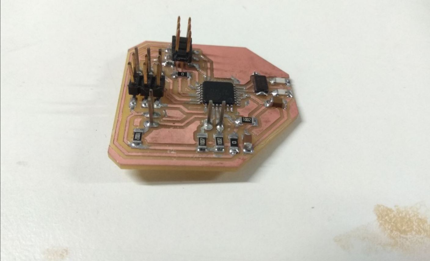
Modified Board
I designed a board using Atmega 328p for controlling the servos and mood lights.I kept it to the minimum by just using two pins each for controlling 2 servos, one pin for controlling the LED,Two pins for communicating with pi and One pin as the analogue audio input from the speaker.
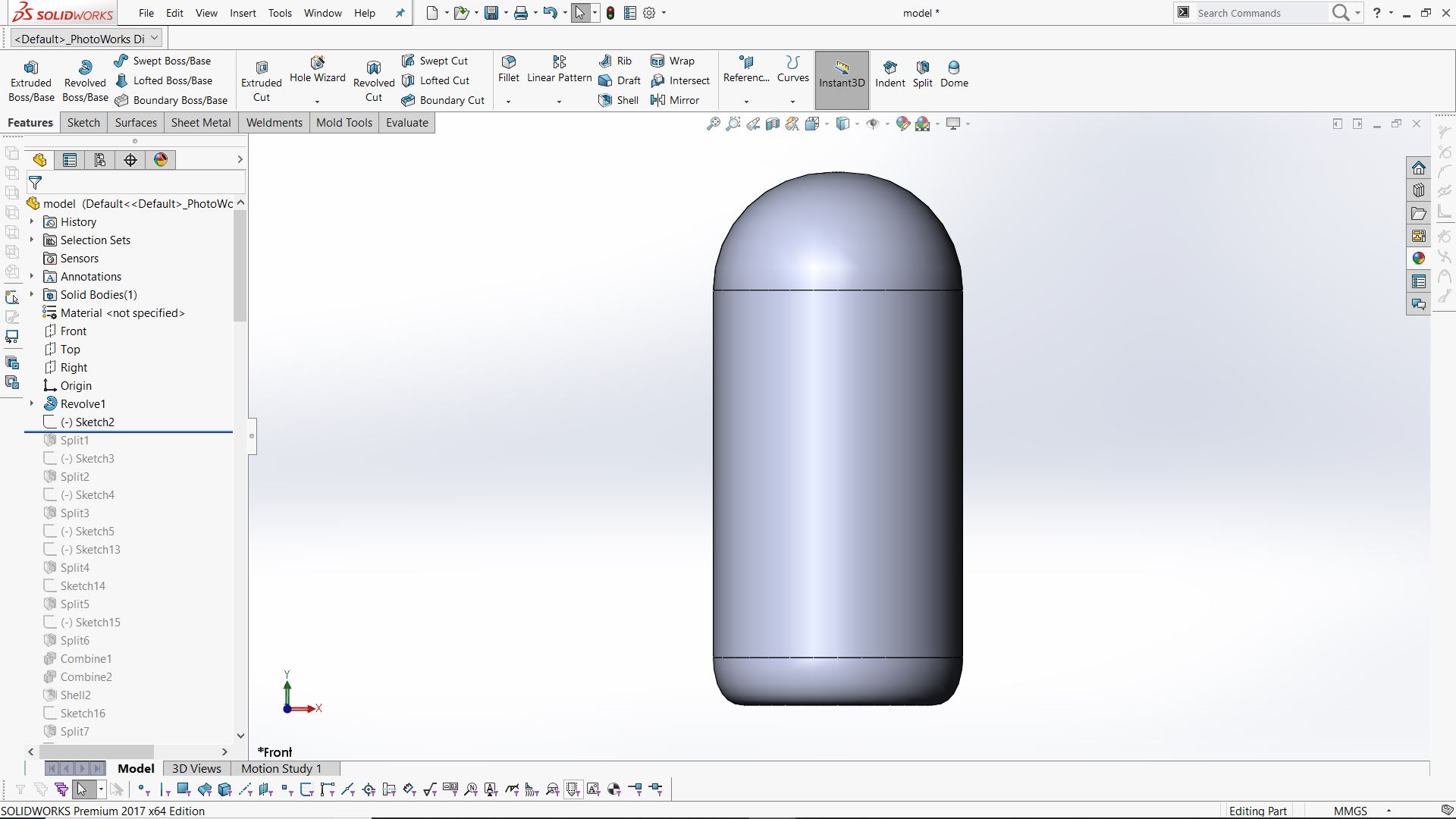
Mechanical Design
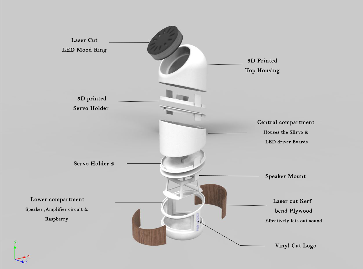
I designed my robot in solidworks and these were the stages I went through.
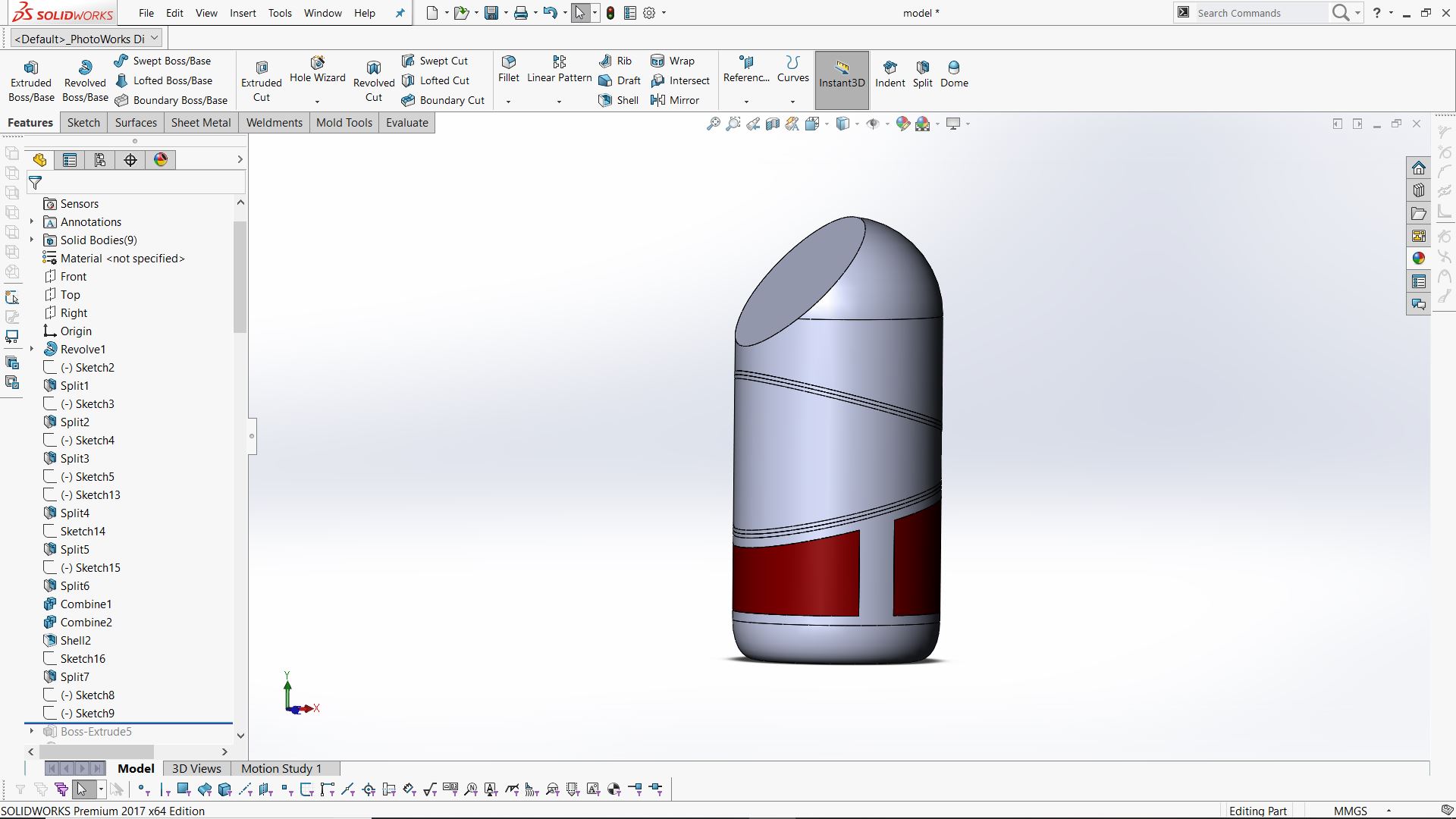
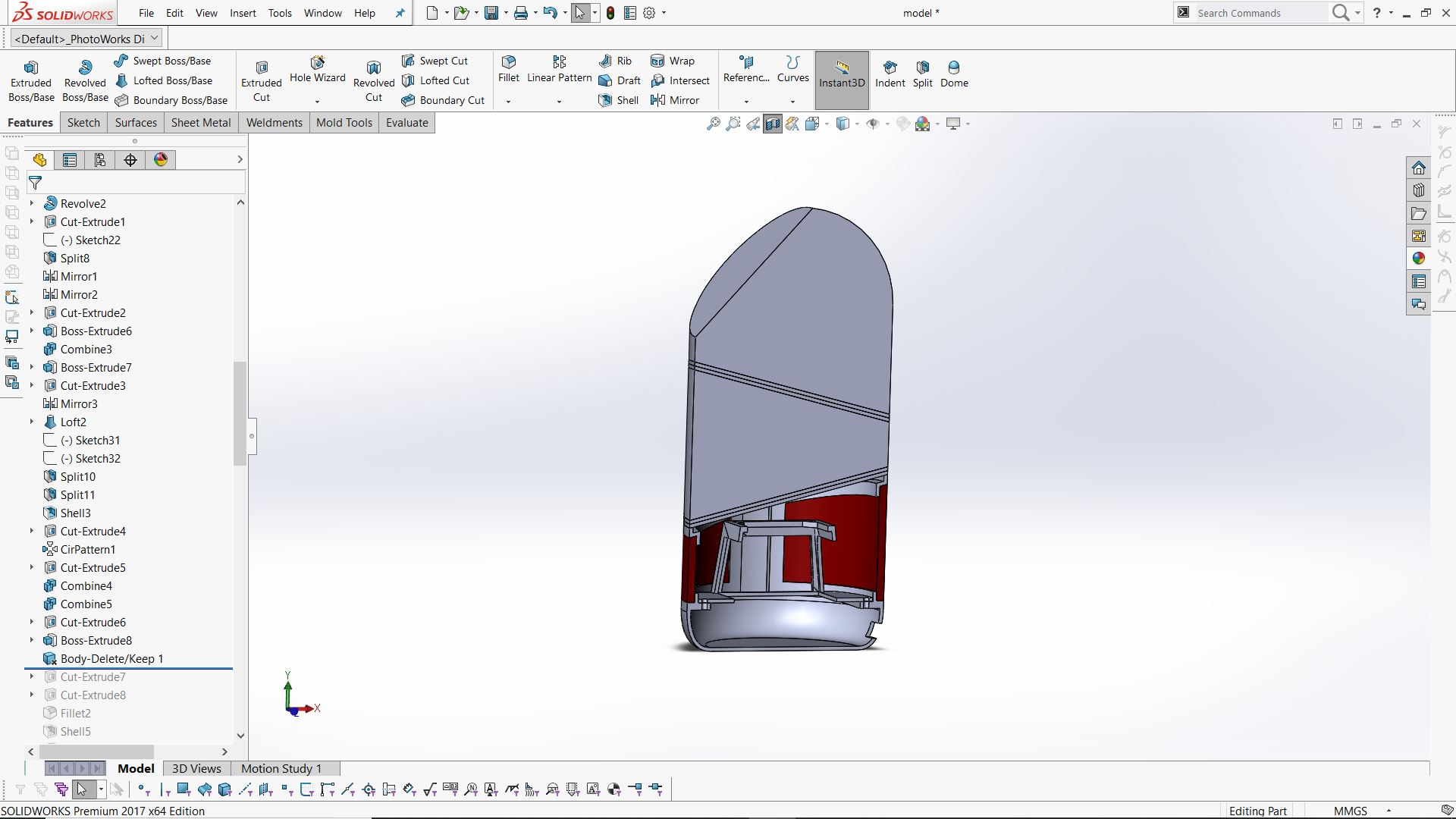
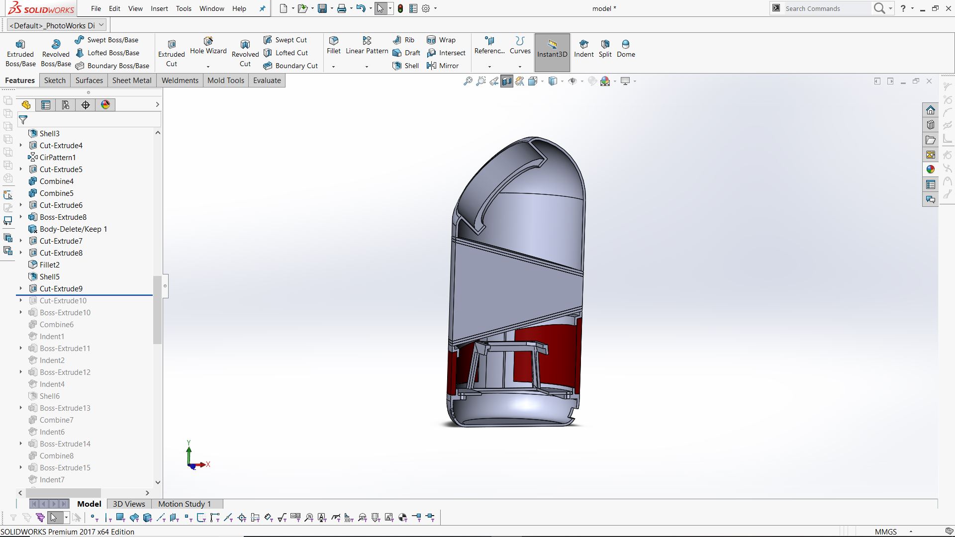

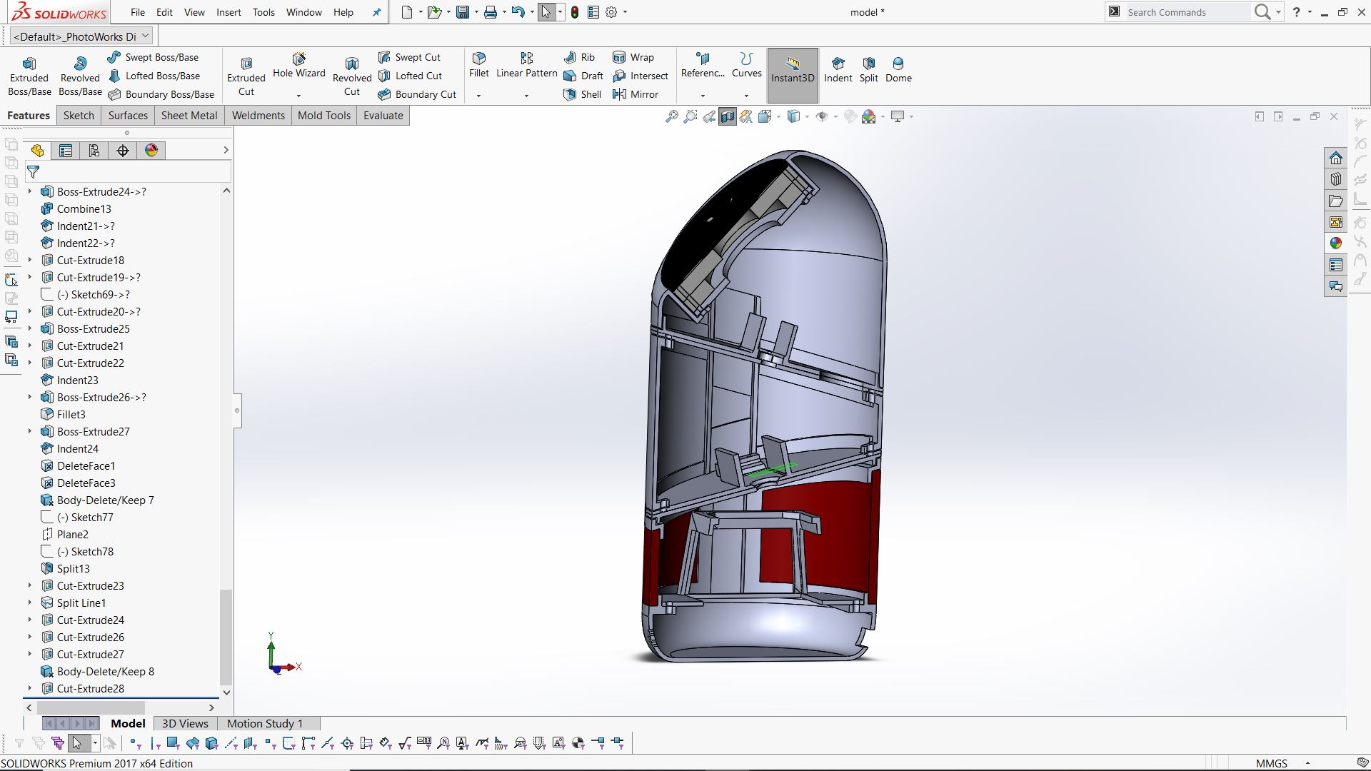
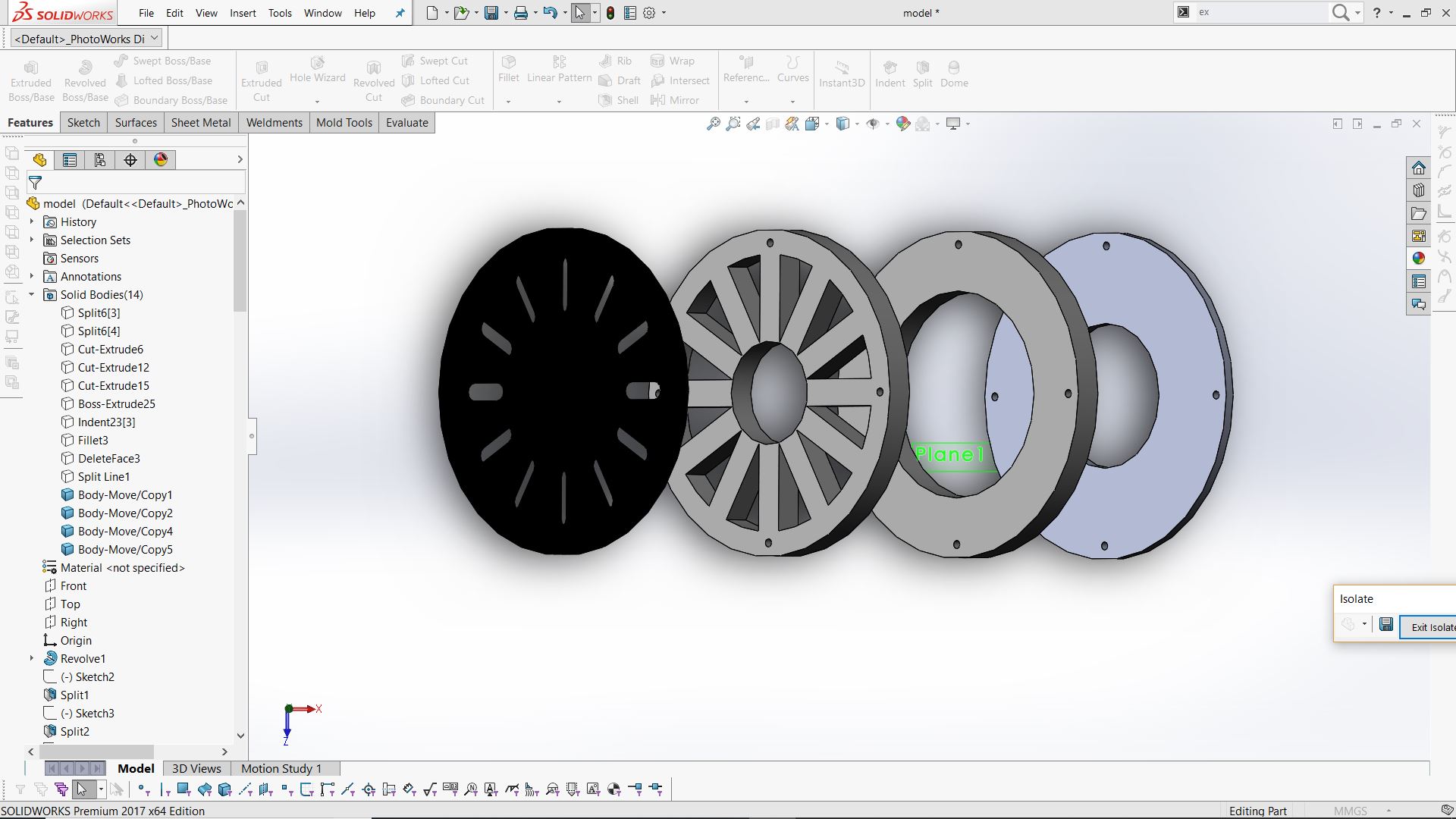
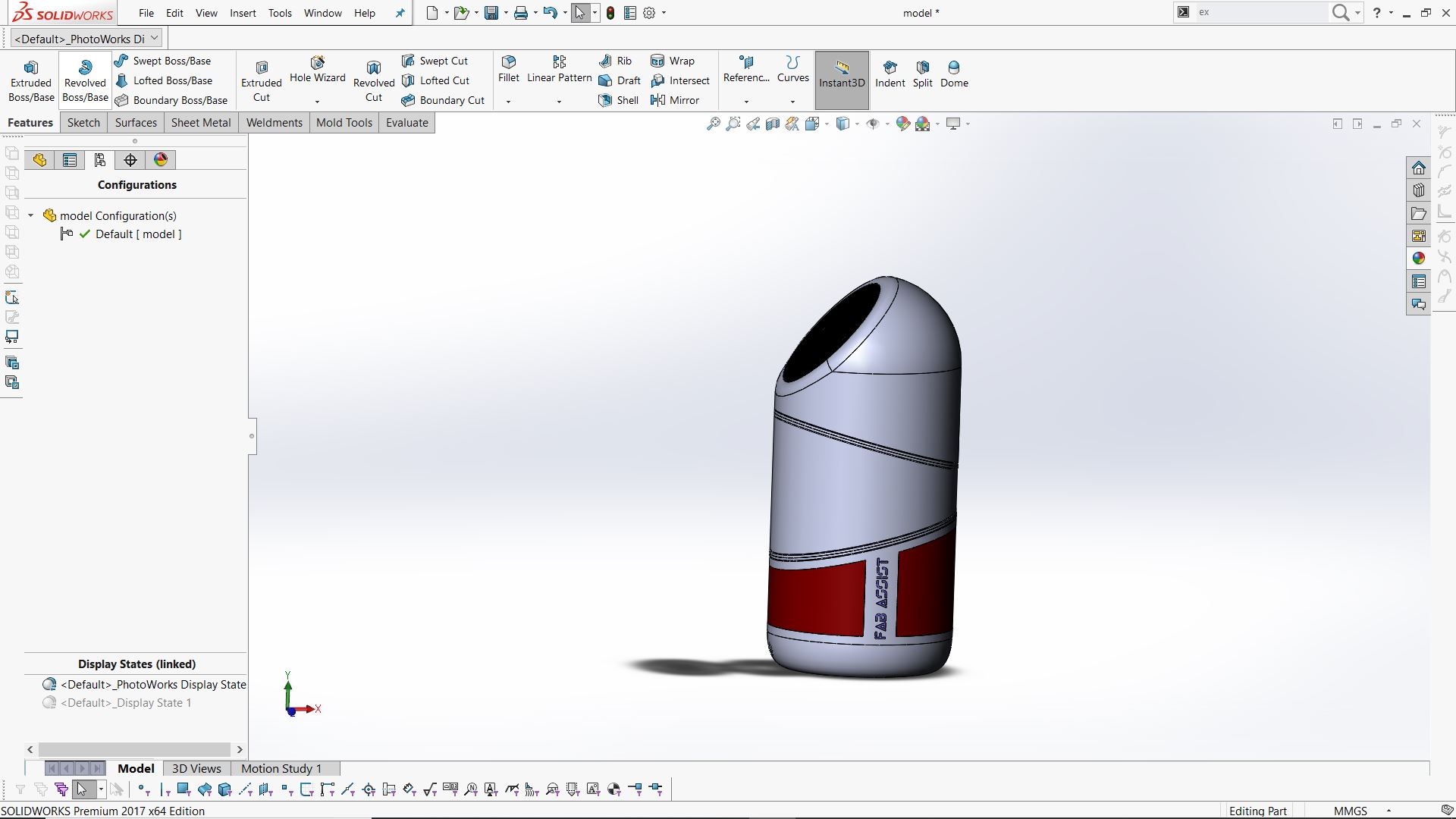
Download the design files here.
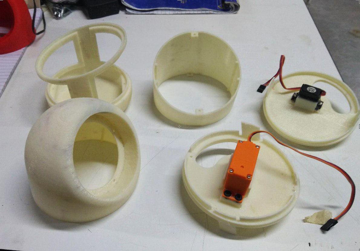
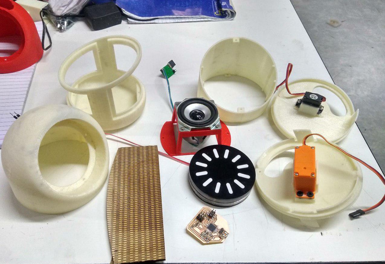
Fabricating the parts
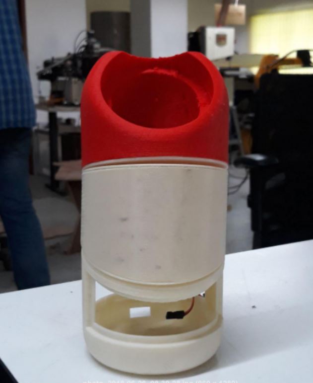
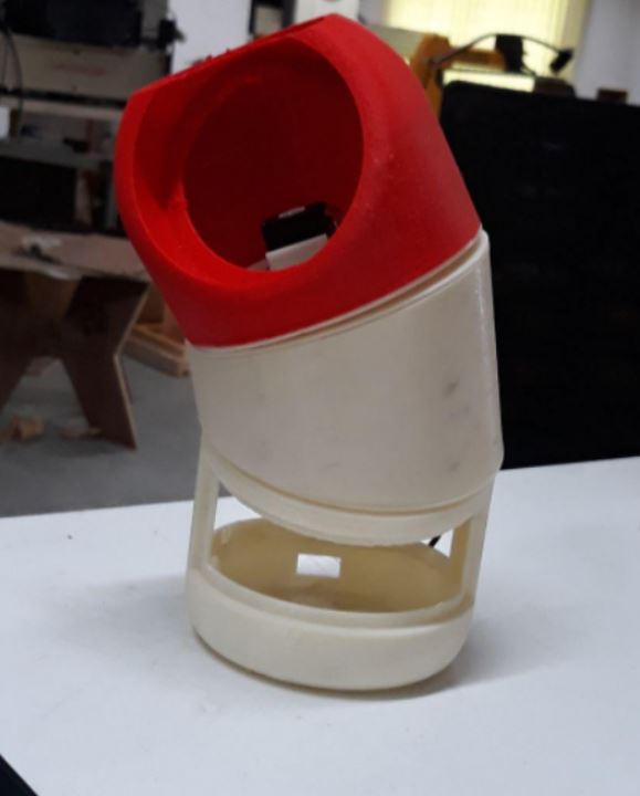
Main body
The main body of the speaker will be mostly 3d printed. You can download all the file for 3D printing here.
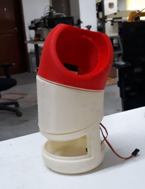
I printed most of the parts in Dimension since our Ultimaker was out of service.
I tried printing the top portion in ultimaker using the red PLA to give some sort of color contrast between head and rest of the body. But the print was stuck midway. So I gave another print in Dimension and went on to assemble my speaker with the parts I already have to see how well they will all fit together.I've already given a clearence of .5mm between the mating parts and it came out to be a pretty good fit.
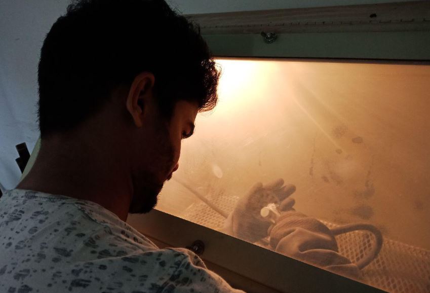
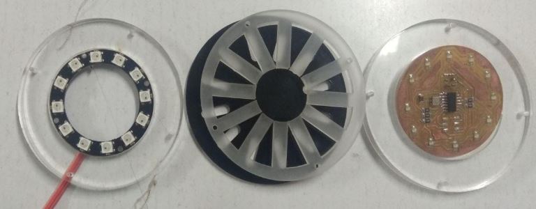
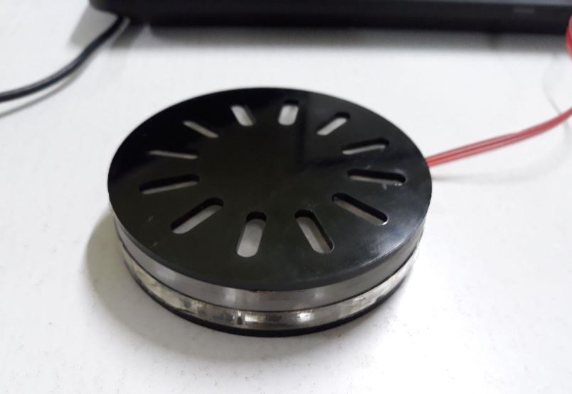
Mood Rings
All the parts of mood rings will be lasercut. Each layers will be laser cut and will be stacked to complete the module.Sand blasting will be used to make the diffusor from the clear acryllic.
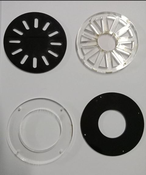
But my Boards stopped working (it was made few weeks before) and I had to improvise. My friend Suhail had a neopixel ring with him and I borrowed to complete my project.
Download the files for laser cutting here.
Kerf Bending
The closure for covering the bottom part will be made from plywood.Kerf bending technique will be used to bend the plywood.
Download the files for 3D printing here.
Assembling
Setting up the Google home.
One can easily setup the google home using google API and a raspberry pi. All the steps are mentioned in official google webpage.Read this article about Google Assistant library for more information.
After setting up the google home next it was time to setup custom actions on your google home. That's how we will be making our assisst dance when I ask him to 'Turn-On'. In this case Raspberry Pi will be sending a high value to the servo control board when I ask it to 'Turn-On'.Similarly the RaspberryPi should send a 0 value when I ask it to 'Turn-Off'
This is how communication will take place in my Board.I have also written another code for the servo Boards to move when it recieves a high value from the Raspberry Pi.Code for bringing the speaker to a neutral position in idle condition and Code for setting up the neo pixels in different moods will also be added to it.
#include
	#include
	#define pinPix 2
	#define numPix 12

	Adafruit_NeoPixel myNeoPixels = Adafruit_NeoPixel(12, 2, NEO_GRB + NEO_KHZ800);
	Servo myservo;
	Servo myservo2;
	int pos = 0;

	void setup() {
		myservo.attach(A1);
		myservo2.attach(A2);
		myNeoPixels.begin();
		Serial.begin(9600);
		pinMode(7, INPUT);
	}

	void loop() {
		int reading = digitalRead(7);
		Serial.println(reading);
		if (reading == HIGH) {
		ledTrail(50, 4, 100, 255, 255, 0, 0, 0);   // Pause; R,G,B foreground; R,G,B backgroun
		move_top(130, 10);
		ledTrail(50, 4, 100, 255, 255, 0, 0, 0);   // Pause; R,G,B foreground; R,G,B backgroun
		move_top(50, 10);
		}

		else
		{move_top(90, 10);
		ledTrail(50, 4, 100, 255, 255, 0, 0, 0);
		}
	}
	void move_top(int dest, int spd) {
		int dir = ((dest - pos) >= 0) ? 1 : (-1);
		while (dest != pos) {
		myservo.write(pos);
		myservo2.write(pos);
		pos += dir;
		delay(spd);
		}
	}
	const byte extra = 4;  // how many ahead, and behind, to light up
	void ledTrail(int pause, int steps, byte Rf, byte Gf, byte Bf, byte Rb, byte Gb, byte Bb) {

		int tmpR, tmpG, tmpB;
		for (int s = 1; s <= steps; s++) {
		tmpR = (Rf * s) / steps;     // Multiply first to avoid truncation errors
		tmpG = (Gf * s) / steps;
		tmpB = (Bf * s) / steps;


		for (int i = 0; i < numPix; i++) {
			myNeoPixels.setPixelColor(i, Rf, Gf, Bf);

			for (int s = 1; s < extra + 1; s++)
			{
			tmpR = (Rf * (extra - s)) / extra;     // Multiply first to avoid truncation errors
			tmpG = (Gf * (extra - s)) / extra;
			tmpB = (Bf * (extra - s)) / extra;
			myNeoPixels.setPixelColor((i + s) % numPix, tmpR, tmpG, tmpB);
			myNeoPixels.setPixelColor((i + numPix - s) % numPix, tmpR, tmpG, tmpB);
			}

			for (int s = steps; s > 0; s--) {
			tmpR = (Rf * s) / steps;     // Multiply first to avoid truncation errors
			tmpG = (Gf * s) / steps;
			tmpB = (Bf * s) / steps;
			}

			myNeoPixels.show();
			delay(pause);
		}
		}
	}
