
Week Twelve
Assignment
What I did
Introduction
This week we were taught about various output devices. Neil gave us an introduction to various output devices that we can try this week. I wanted to do something that I'll be using for my final project as well. I wanted to control 2 servo motors and a speaker in my final project. So the idea was to design a board so that I can control 2 servo motors and to add a pin to connect to the audio amplifier as well. I will not be making the amplifier this week as the maximum power of the amplifier that can be made using the smd components available at the fab inventory is 1W. Since I wanted more power I thought to use an amplifier that was lying around in the lab .
Basics
A servomotor is a rotary actuator or linear actuator that allows for precise control of angular or linear position, velocity, and acceleration. It consists of a suitable motor coupled to a sensor for position feedback. It also requires a relatively sophisticated controller, often a dedicated module designed specifically for use with servomotors.(wiki)
I read about servo and this website was really helpfull.
Design
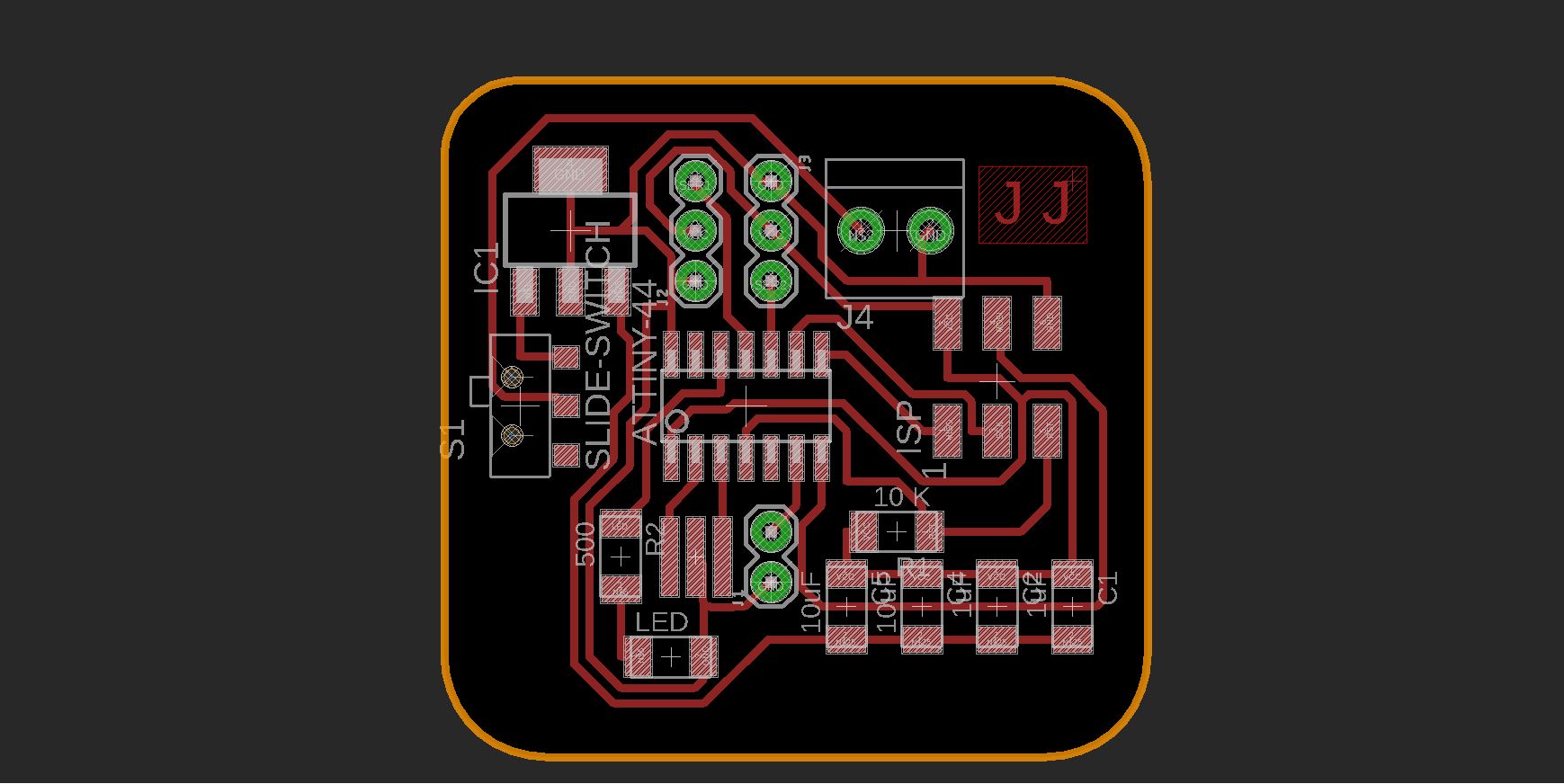
I started designing in Eagle.The idea was to use Atmega 328p microcontroller for controlling the servos. I read the Datatsheet of the microcontroller to know about the pins and other detaills.
I choose this one because this one has bigger memory and has more pins so that we can add more components further.I also heard that we have to add extra libraries to Arduino Ide while programming Attiny for servos. So, to avoid this complication I selected Atmega 328p .
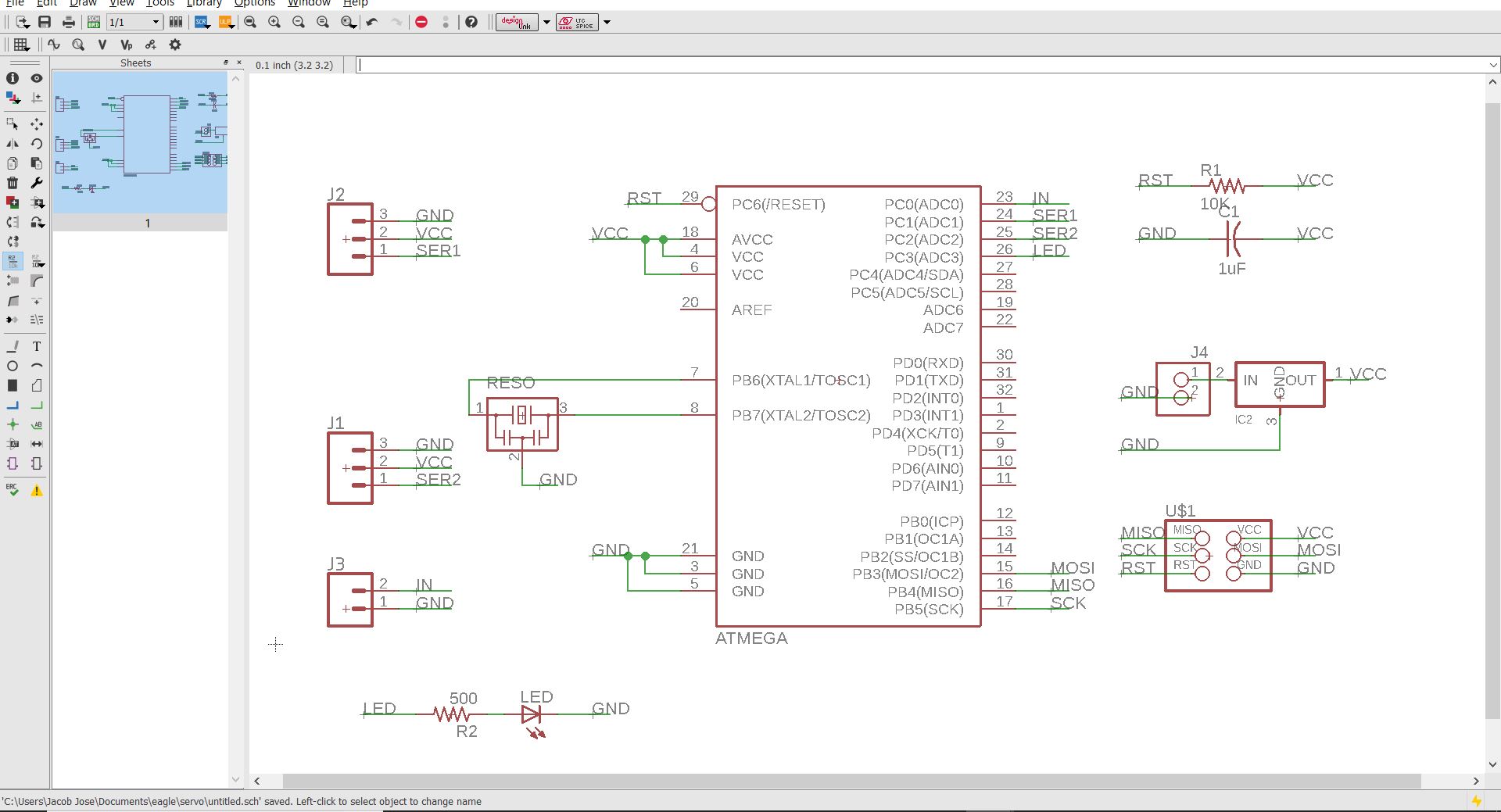
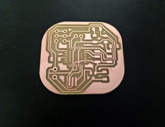
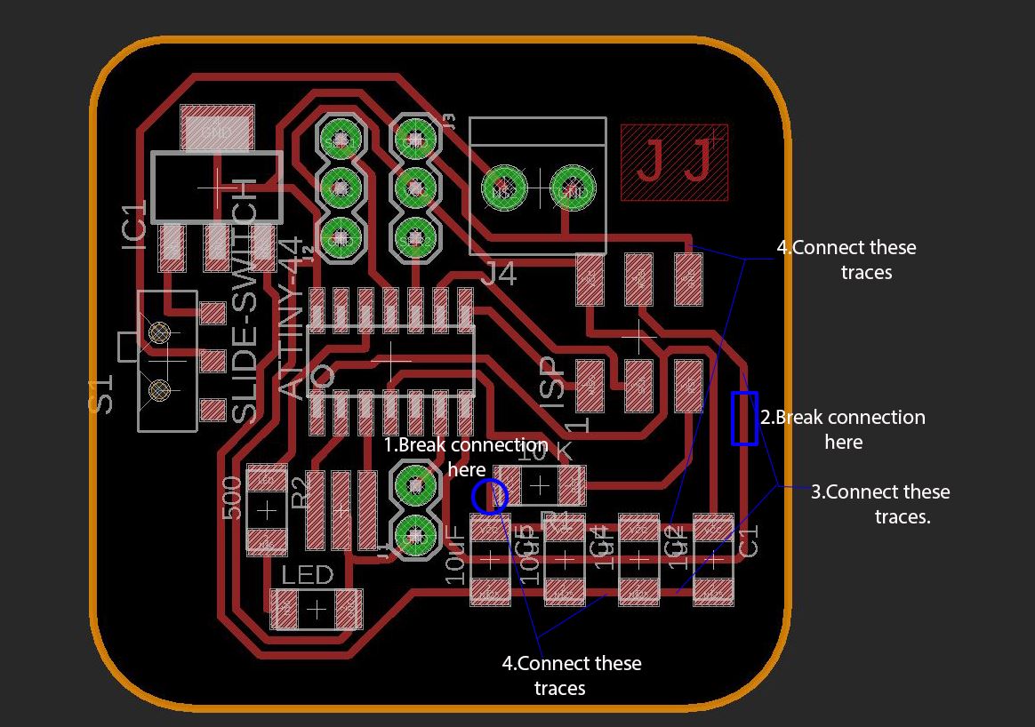
First I went with the autorooting option. But the maximum I could reach was about 70%.So I manually rooted the rest.
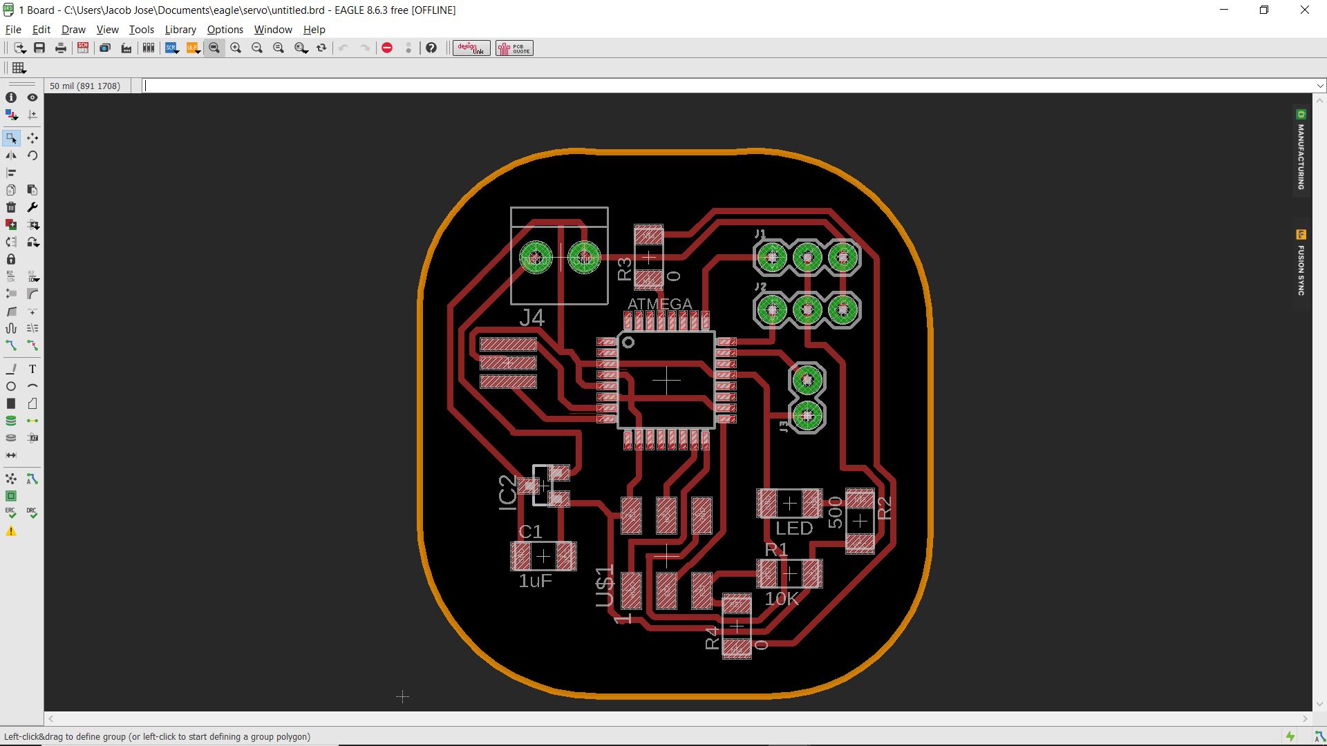
Since there are through hole components in this design we have to make three images for traces,cutout and drill holes.You can download all the design files here
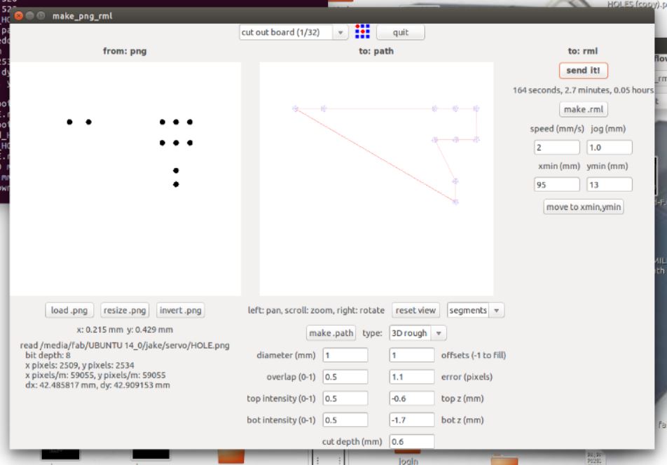
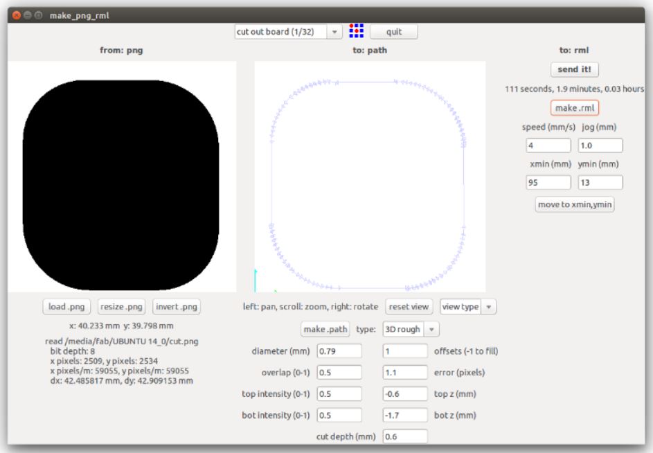
Milling PCB
I used the Modella MDX 20 milling machine available at our lab. The detailed explanation of the machine and its operation is explained in the previous weeks.
Making the board
Testing the board
I first connected the board using my fab ISP. The power LED was on but I see some smoke coming out. I immediately removed the fab ISP and checked what it was. I found that my voltage regulator was extremely overheated. Then I checked for any shorts or bridges in the circuit but I couldn't find any :(.
Then I connected my board to 9v external battery supply. Then my voltage regulator overheated and exploded.
Debugging
I gain checked for the shorts but I couldn't find any. Then I called my instructor he also checked my board but couldn't find anything major. He made some suggestions in the existing board to make it work
He asked me to change the 10k resistor and place it between the output of the voltage regulator and Reset pin of the MC.He also asked me to remove the connection to LED nd check the board again.
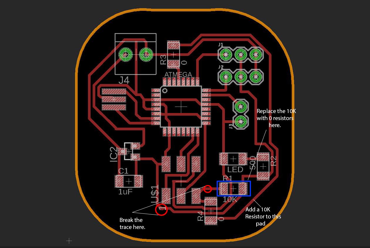
I replaced the voltage regulator and made the given changes to the board and again connected it using fab ISP. But the results were same and I got another heated, faulty voltage regulator.
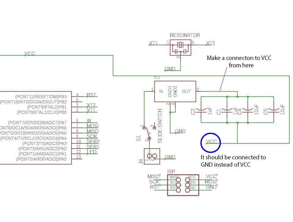
Digging more into the details of the voltage regulator and reading its datasheet I found that we need to add one 1 uF capacitor each in the input and output of the voltage regulator.With this, I concluded that this could be the one reason for my faulty board. So I thought to design another board with these changes included.
Board 2
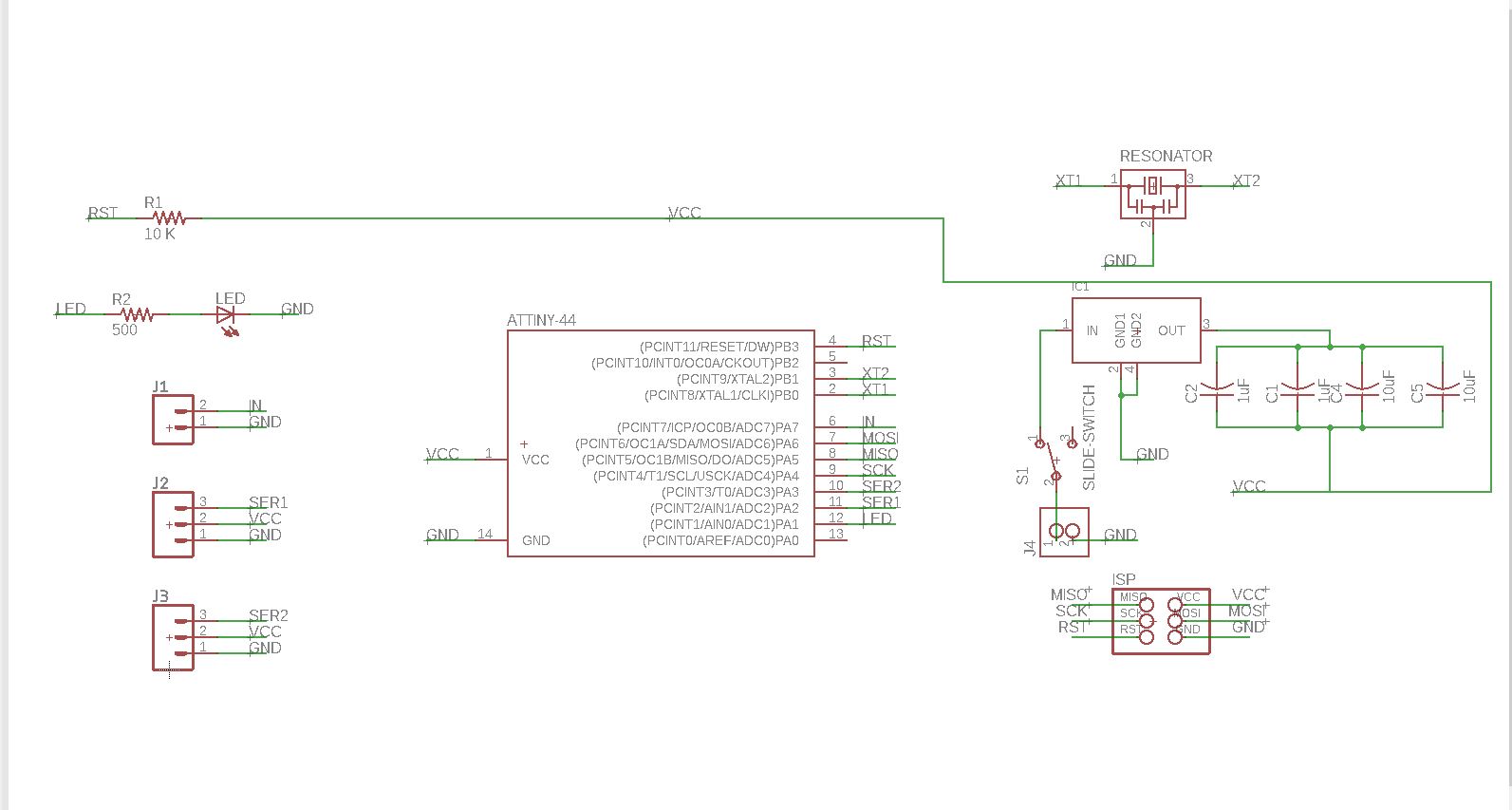
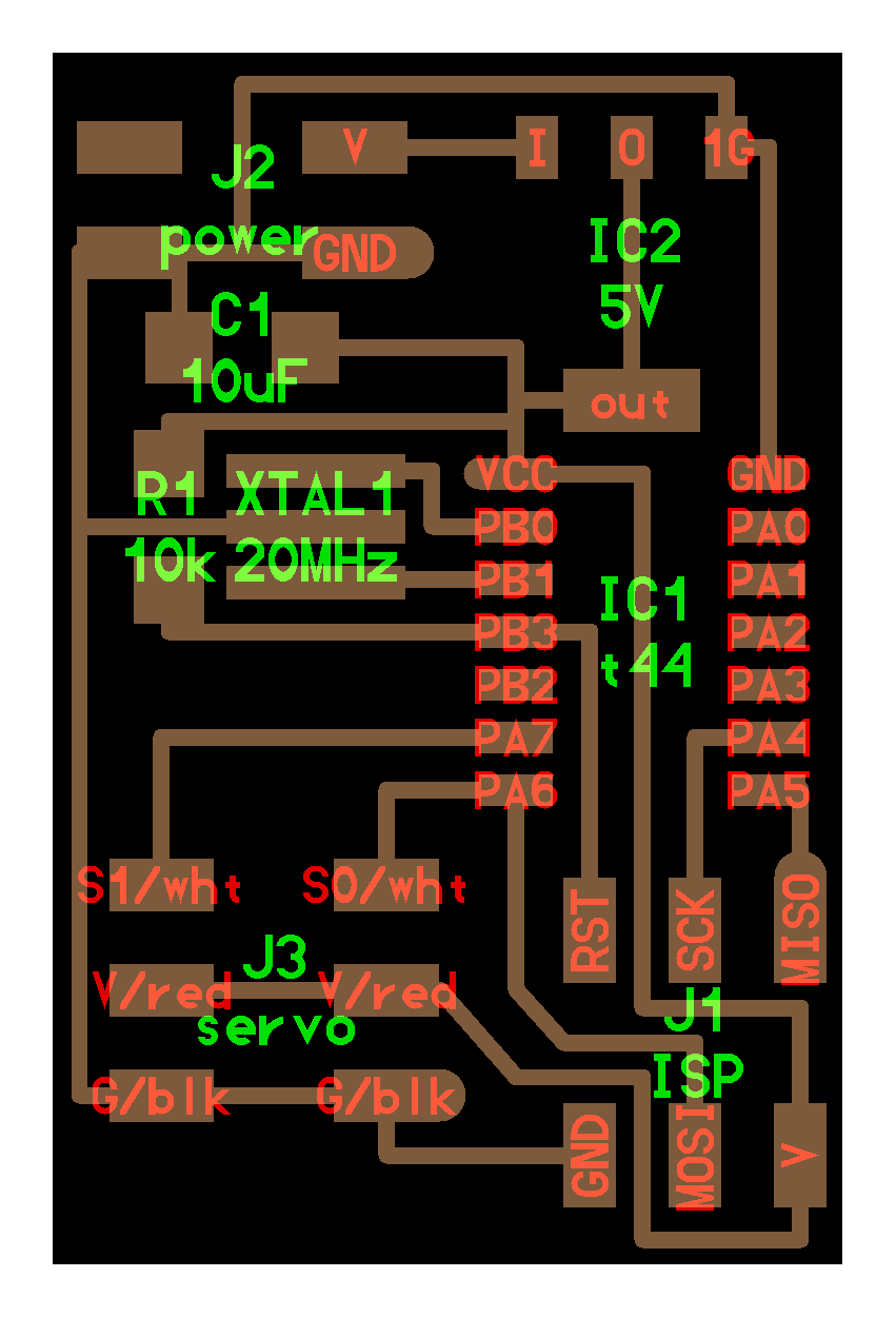
This time I thought to refer the neils board and use similar components to avoid further complications. So I am using a Attiny44 instead of a Atmega 328p in this board. I am also using a bigger regulator like the one used in neils board.
Designing the board
Before starting the design I referred the Datasheet of the voltage regulator and found that I have to use a 22uF capacitor in the output of the voltage regulator. Going through the inventory I realized that we didn't have a 22uF capacitor and will have to use two 10uF capacitors and two 1uF capacitors in parallel to serve the same purpose.
Download the complete Design files here.
Milling the board
I used the Modella MDX 20 milling machine for milling the PCB. The details about the machine operation is explained in the previous weeks.
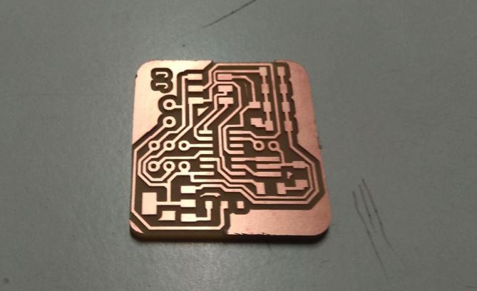
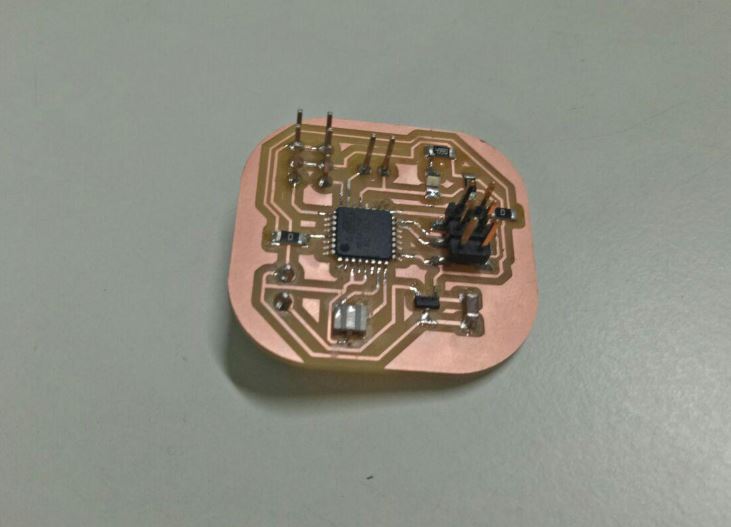
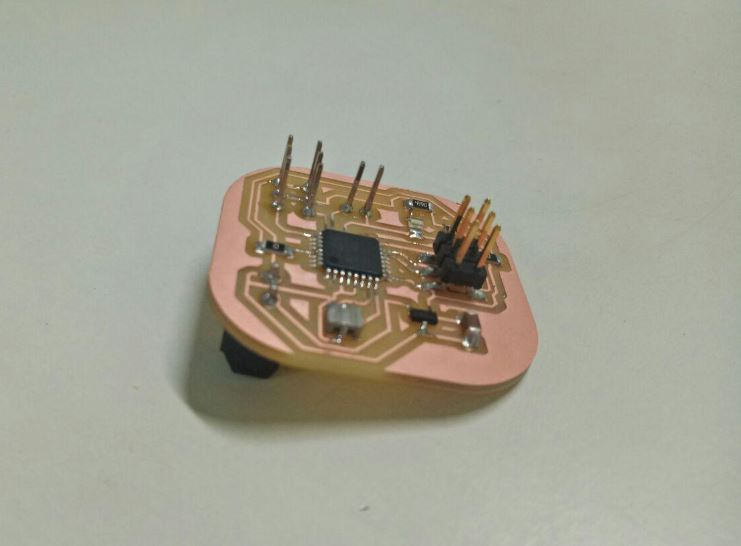
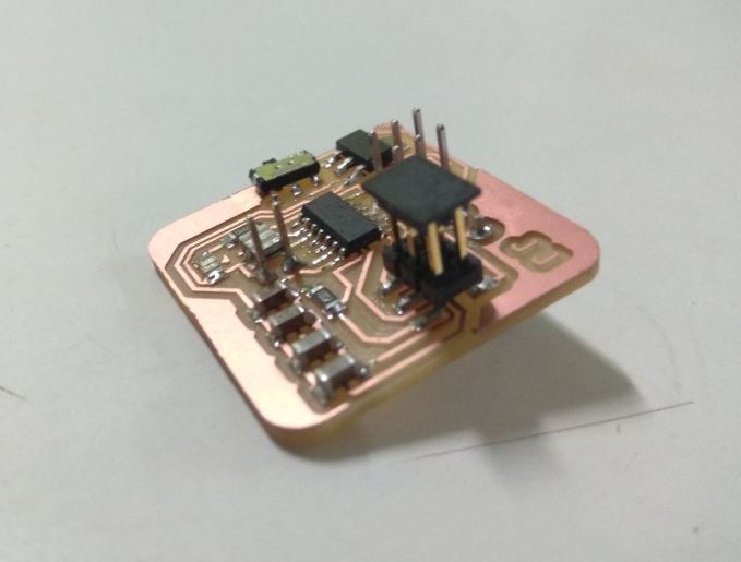
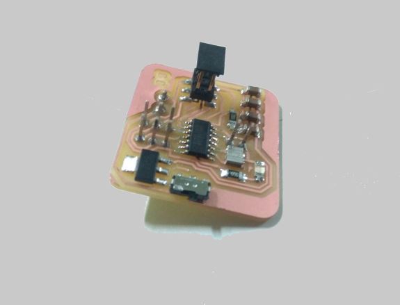
Soldering components
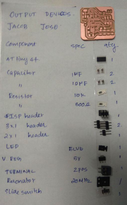
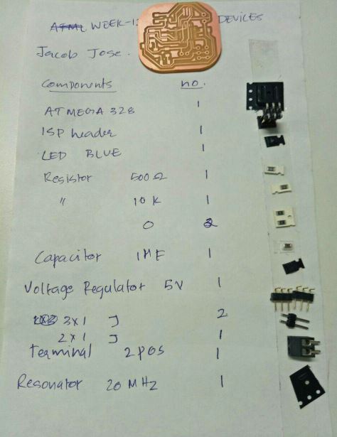
Components
Testing the board
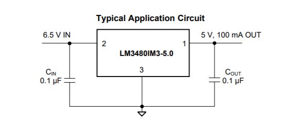
I connected my board using fab ISP and I encountered the same problem that is faced in my previous board and I saw smoke coming from the voltage regulator.I had to figure out the problem this time and I went through the datasheet of the voltage regulator to see the typical circuit diagram.
Troubleshooting
The typical circuit of the voltage regulator is given here
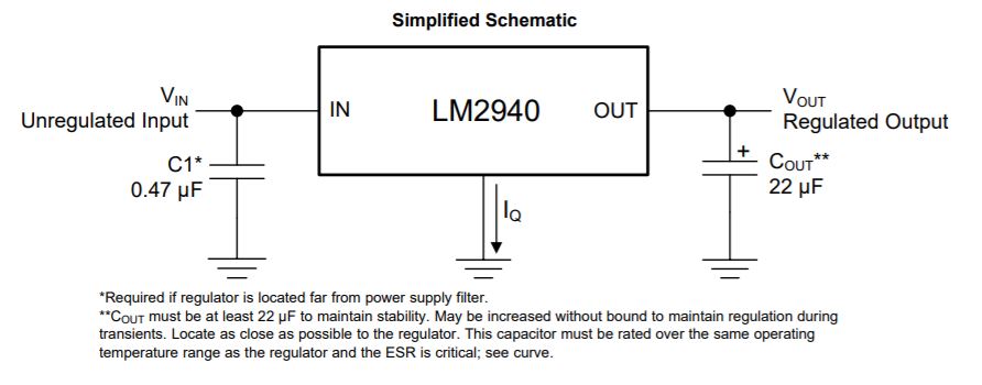
I checked my schematic and found that the capacitors in the output of the voltage regulator are not grounded and the vcc should be taken directly from the output of the voltage regulator.

I tested my board again and the overheating persisted even after these changes. I was really frustrated and then I started checking each component. There was no name slip in the voltage regulator compartment so I had to take it to the magnifying glass to read the details. I found that the voltage regulator we had in our inventory is ZLD 17-50. So I checked its datasheet and found it had an entirely different pinout even though both the voltage regulators looked the same.
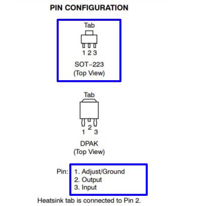
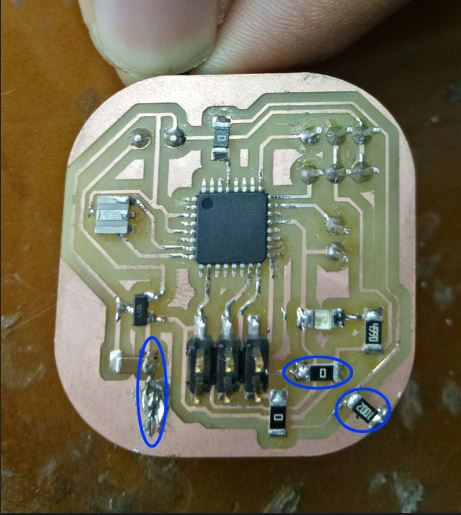
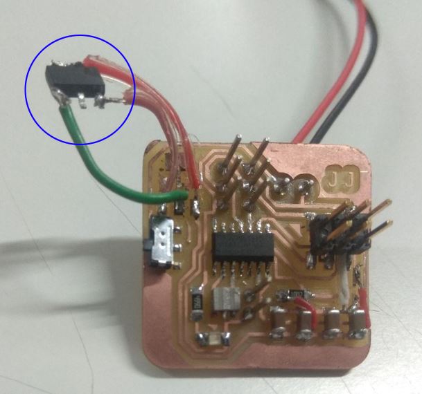
I soldered the Voltage regulator to the board using some jumper wires according to the pinout from the datashee tand tested it. This time there was no overheatinng :)
Programming the board
I connected my board to the pc using the fab ISP and I used Arduino IDE to write the code to rotate my servo.I used the SoftwareServo library foR rotating the servos.
		#include

		SoftwareServo servo;

		void setup()
		{
			servo.attach(2);}

		void loop() {
			int pos;
			for(pos = 0; pos < 90; pos += 1) {
				servo.write(pos);
				delay(10);
				SoftwareServo::refresh();
			}
			for(pos = 90; pos>=1; pos-=1) {
				servo.write(pos);
				delay(10);
				SoftwareServo::refresh();
			}
		}
Final Results
Group Assignment
This weeks group assignment was to measure the power consumption of the output devices we used. We measured the power conception of Buzzer, Servo motor and the LCD Display.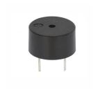
We refered the datasheet and it showed the values 3-6V DC / 25mA but the values we obtained was around 19mA in 5V
We referred the datasheet but there was no details regarding the power consumption in it. So we thought to measure it anyway. Before measuring the power consumption of servos we need to first connect a low-value resistor across the ground of servos and connect the oscilloscope across it.We used a 100 ohm shunt resistor for this purpose.And we can measure the current using basic ohms law.The value we got was around 75mA.
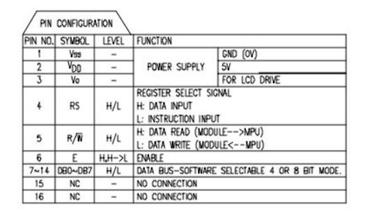
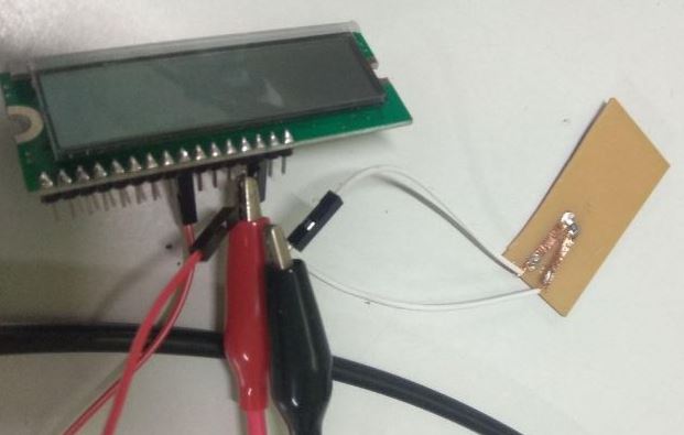
We frist refered the pin configuration and connected a shunt resistor accross the ground pin ie;VSS and a 5v is given to the VDD pin. Current is then measured using the multimeter and the value we got was around 79.8 uA but its the value of flow current.To measure the power consumption at the operating conditions we have to provide a HIGH value to the E-Enable pin of the LCD display. The current measured after this was about 513uA.
