Networking and communications
The assigment page
Design and build a wired &/or wireless network connecting at least two processors.
⇝ Making boards ⇝ Programming ⇝ Second making boards ⇝ Second programming
My radio transmitters are RF24. Neil gave us a page with librairies: http://playground.arduino.cc/InterfacingWithHardware/Nrf24L01
I try the first one but I did'nt understand how to use it with an Attiny. There's an exemple but it's for interfacing with an Arduino. And when I looking for explanations on internet, a lot of people had issues.
Those people uses the library called Mirf. I try to use it but it doesn't work. It seems that the pins were not the same.
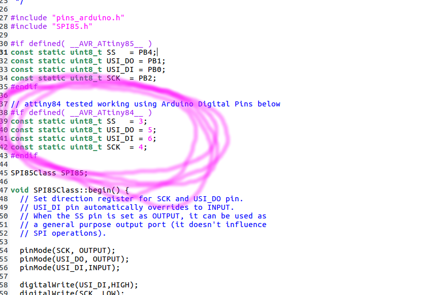
The library is using a file called SPI85.cpp where pins references are stored. I changed it to my value:
And run this sketch, one of the library's example:
/*
This is an attiny84 example code for the nRF24L01 that can communicate with RF24 library
All the support files and libraries for the attiny for nRF24L01 is at repo listed below
* repo : https://github.com/stanleyseow/arduino-nrf24l01/
* Author : Stanley Seow
* e-mail : stanleyseow@gmail.com
* date : 8 Aug 2013
Some default values to take note when using this mirf/spi85 library
Uses Mirf forked library from https://github.com/xdarklight/arduino-nrf24l01
- node addressing is similar to RF24 libs but the bytes are flipped
byte TADDR[] = {0xe3, 0xf0, 0xf0, 0xf0, 0xf0}; will matches receiver node of RF24 below
const uint64_t pipes[2] = { 0x7365727631LL, 0xF0F0F0F0E3LL };
The repo for the RF24 lib is at https://github.com/stanleyseow/RF24/
Added TinyDebugSerial to the codes for TX only serial debugging
https://code.google.com/p/arduino-tiny/
*/
#include <SPI85.h>
#include <Mirf.h>
#include <MirfHardwareSpi85Driver.h>
#include <SoftwareSerial.h> // SoftwareSerial allows serial com with Attiny
#define rxPin 3
#define txPin 5
SoftwareSerial mySerial(rxPin, txPin);
// This USI was defined in SPI85.cpp
// Not to be confused with SPI (MOSI/MISO) used by ICSP pins
// Refer to page 61 of attiny84 datahseet
//
//#define USI-DO 5
//#define USI-DI 6
//#define USCK 4
#define CE 1
#define CSN 2
// ATMEL ATTINY84 / ARDUINO
//
// +-\/-+
// VCC 1| |14 GND
// SerialTx (D 0) PB0 2| |13 AREF (D 10)
// (D 1) PB1 3| |12 PA1 (D 9)
// RESET PB3 4| |11 PA2 (D 8)
// PWM INT0 (D 2) PB2 5| |10 PA3 (D 7) CE
// SS/CSN (D 3) PA7 6| |9 PA4 (D 6) USCK
// USI-DI (D 4) PA6 7| |8 PA5 (D 5) USI-DO
// +----+
int bufferSize = 0;
char buffer[32] = "";
unsigned int counter = 0;
uint8_t nodeID = 0;
void setup(){
mySerial.begin( 9600 ); // for tiny_debug_serial
Mirf.cePin = CE;
Mirf.csnPin = CSN;
Mirf.spi = &MirfHardwareSpi85;
Mirf.init();
// This address is compatible with my example of rpi-hub or nRF24_Arduino_as_hub
// at repo https://github.com/stanleyseow/RF24/examples/
byte RADDR[] = {0xe7, 0xde, 0xde, 0xde, 0xde};
byte TADDR[] = {0xe9, 0xde, 0xde, 0xde, 0xde};
// Get nodeID from TXADDR
nodeID = *TADDR & 0xff;
// Compatible with RF24
Mirf.baseConfig = _BV(EN_CRC) | _BV(CRCO);
// RF_DR_LOW, RF_DR_HIGH
// 00 - 1Mbps
// 01 - 2Mbps
// 10 - 250Kbps
// 11 - Reserved
// 1<<2 & 1<<1 is for Max RF Power
Mirf.configRegister( RF_SETUP,( 1<<RF_DR_LOW | 0<<RF_DR_HIGH ) | 1<<2 | 1<<1 );
Mirf.channel = 0x55; // Same as rpi-hub and sendto_hub ( channel 85 )
Mirf.setRADDR(RADDR);
Mirf.setTADDR(TADDR);
Mirf.config();
// Enable dynamic payload on the other side
Mirf.configRegister( FEATURE, 1<<EN_DPL );
Mirf.configRegister( DYNPD, 1<<DPL_P0 | 1<<DPL_P1 | 1<<DPL_P2 | 1<<DPL_P3 | 1<<DPL_P4 | 1<<DPL_P5 );
delay(100);
// Print out register readinds for important settings
uint8_t rf_ch, rf_setup = 0;
byte tx_addr[5];
byte rx_addr[5];
Mirf.readRegister(RF_CH, &rf_ch,sizeof(rf_ch));
Mirf.readRegister(RF_SETUP, &rf_setup, sizeof(rf_setup));
Mirf.readRegister(TX_ADDR, tx_addr, sizeof(tx_addr));
Mirf.readRegister(RX_ADDR_P1, rx_addr, sizeof(rx_addr));
mySerial.println();
mySerial.print("RF_CH :0x");
mySerial.println(rf_ch,HEX);
mySerial.print("RF_SETUP :0x");
mySerial.println(rf_setup,HEX);
mySerial.print("TX_ADDR :");
for ( int i=0;i<5;i++ ) { // Loop 5 times, print in HEX
mySerial.print( tx_addr[i], HEX);
}
mySerial.println();
mySerial.print("RX_ADDR :");
for ( int i=0;i<5;i++ ) { // Loop 5 times, print in HEX
mySerial.print( rx_addr[i], HEX);
}
mySerial.println();
delay(1000); // For serial debug to read the init config output
}
void loop(){
uint8_t sent = false;
unsigned long timer1;
timer1 = millis();
counter++;
sprintf(buffer,"%2X,%u,%08lu",nodeID,counter,timer1);
Mirf.payload = strlen(buffer);
mySerial.print("Len :");
mySerial.print(strlen(buffer));
mySerial.print(" Buffer :");
mySerial.println(buffer);
Mirf.send((byte *) buffer);
while( Mirf.isSending() )
{
delay(1);
sent = true; // Sent success
}
if (sent) {
mySerial.print("Sent :");
mySerial.println(buffer);
} else {
}
delay(1000);
} // End loop()
When I look the serial monitor, I have some funny characters who appears each second. A least,
I have something.
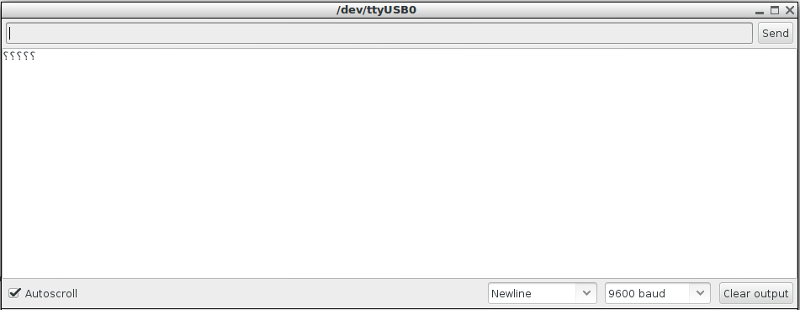
So perhaps it's because there's differents libraries, who's not using the same Attiny84 pinout between each other so I thought that in the confusion, I made something wrong.
We know that Martin Risseeuw
succeed to get the nF24 works for communication between 2 Attiny84 (I need a 84 because of the number of pins, gyro needs 4 as the nf24).
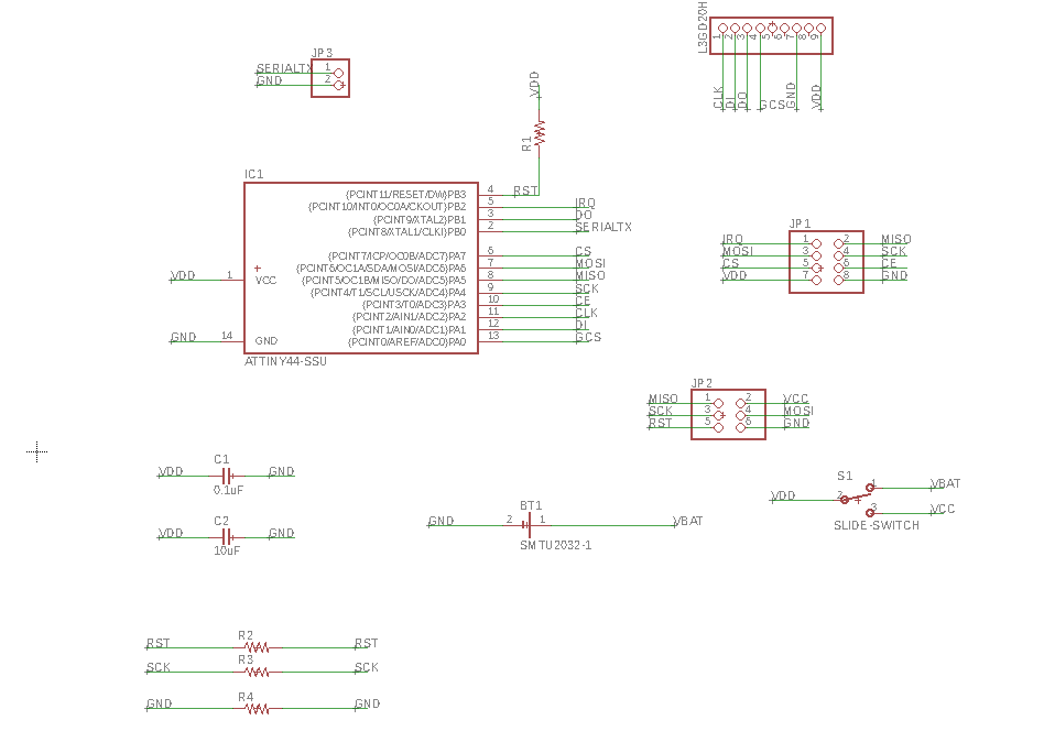
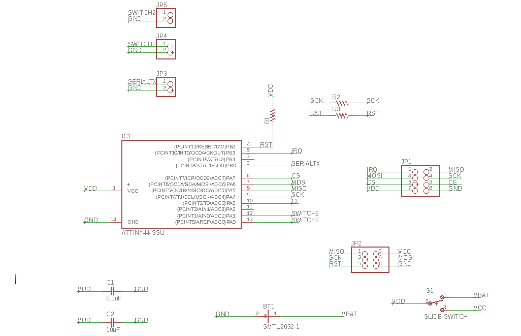
So I design 2 boards following exactly Martin's pinout:
// ATMEL ATTINY84 / ARDUINO
//
// +-\/-+
// VCC 1| |14 GND
// SerialTx (D 0) PB0 2| |13 AREF (D 10)
// (D 1) PB1 3| |12 PA1 (D 9)
// RESET PB3 4| |11 PA2 (D 8)
// PWM INT0 (D 2) PB2 5| |10 PA3 (D 7) CE
// SS/CSN (D 3) PA7 6| |9 PA4 (D 6) USCK
// USI-DI (D 4) PA6 7| |8 PA5 (D 5) USI-DO
//
So I design 2 boards (they're pretty the same boards with a different pinout than
Networking and communications week).
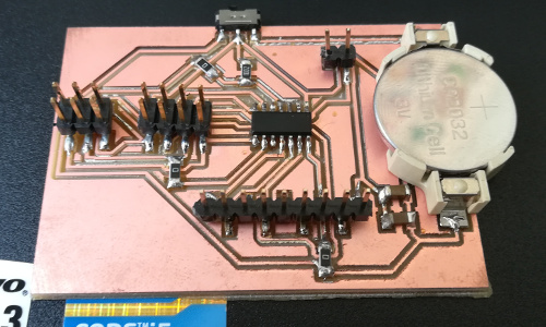
One with the gyro:
-1 Attiny84
-1 0.1uF Capacitor
-1 10uF Capacitor
-3 0 Ohm resistors
-1 10k resistor
-1 2032 battery holder
-1 slide-switch
-1x9 pinheads (for gyro)
-1x2 pinheads (for serial)
-2x4 pinheads (for nF24)
-2x6 pinheads (for programming)
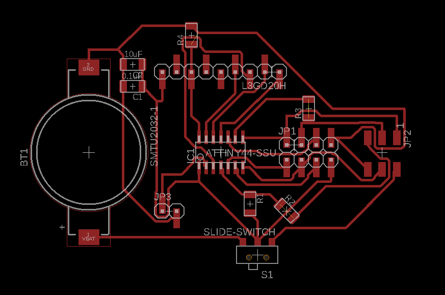
The board after milling it and solder the components:
The other one with just 2 outputs pins:
-1 Attiny84
-1 0.1uF Capacitor
-1 10uF Capacitor
-2 0 Ohm resistors
-1 10k resistor
-1 2032 battery holder
-1 slide-switch
-1x4 pinheads (for outputs)
-1x2 pinheads (for serial)
-2x4 pinheads (for nF24)
-2x6 pinheads (for programming)
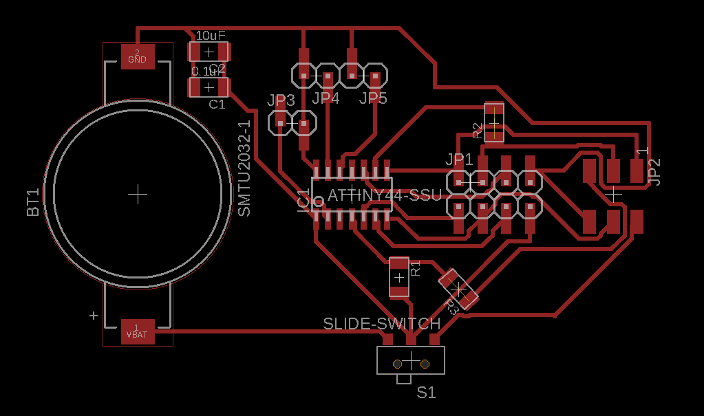
The board after milling it and solder the components:
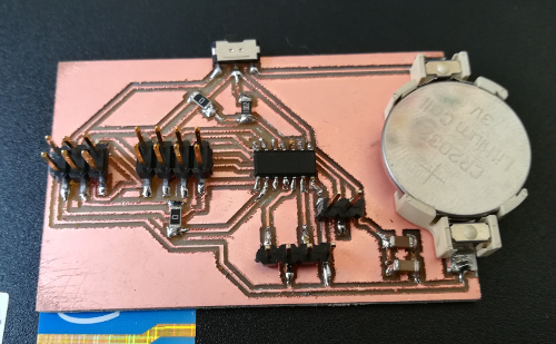
I tested it with the regular
avrdude -c usbtiny -p t84 and they works!
Programming the radio boards
So now I have the good boards with the good pinout, it's time programming. To avoid conflict between libraries, versions, etc, I tried on another computer with Arduino 1.5.
I downloaded
this library.
I downloaded
this Arduino Tiny Core.
And I put this code from Martin's page in one of the board:
Ping Client
/*
* repo : https://github.com/stanleyseow/arduino-nrf24l01/
* Author : Stanley Seow
* e-mail : stanleyseow@gmail.com
* date : 8 Aug 2013
* Edited by : By Martin on 5 may 2014
Some default values to take note when using this mirf/spi85 library
Uses Mirf forked library from https://github.com/xdarklight/arduino-nrf24l01
- node addressing is similar to RF24 libs but the bytes are flipped
byte TADDR[] = {0xe3, 0xf0, 0xf0, 0xf0, 0xf0}; will matches receiver node of RF24 below
const uint64_t pipes[2] = { 0x7365727631LL, 0xF0F0F0F0E3LL };
The repo for the RF24 lib is at https://github.com/stanleyseow/RF24/
*/
#include <SPI85.h>
#include <Mirf.h>
#include <MirfHardwareSpi85Driver.h>
#include <nRF24L01.h>
// This USI was defined in SPI85.cpp
// Not to be confused with SPI (MOSI/MISO) used by ICSP pins
// Refer to page 61 of attiny84 datahseet
//
//#define USI-DO 5
//#define USI-DI 4
//#define USCK 6
#define CE 7
#define CSN 3
// ATMEL ATTINY84 / ARDUINO
//
// +-\/-+
// VCC 1| |14 GND
// SerialTx (D 0) PB0 2| |13 AREF (D 10)
// (D 1) PB1 3| |12 PA1 (D 9)
// RESET PB3 4| |11 PA2 (D 8)
// PWM INT0 (D 2) PB2 5| |10 PA3 (D 7) CE
// SS/CSN (D 3) PA7 6| |9 PA4 (D 6) USCK
// USI-DI (D 4) PA6 7| |8 PA5 (D 5) USI-DO
// +----+
int bufferSize = 0;
char buffer[32] = "";
unsigned int counter = 0;
uint8_t nodeID = 0;
void setup(){
Serial.begin( 9600 ); // for tiny_debug_serial
Mirf.cePin = CE;
Mirf.csnPin = CSN;
Mirf.spi = &MirfHardwareSpi85;
Mirf.init();
/*
* Configure reciving address.
*/
Mirf.setRADDR((byte *)"clie1");
/*
* Set the payload length to sizeof(unsigned long) the
* return type of millis().
*
* NB: payload on client and server must be the same.
*/
Mirf.payload = sizeof(unsigned long);
/*
* Write channel and payload config then power up reciver.
*/
/*
* To change channel:
*
* Mirf.channel = 10;
*
* NB: Make sure channel is legal in your area.
*/
Mirf.config();
Serial.println("Beginning ... ");
}
void loop(){
unsigned long time = millis();
Mirf.setTADDR((byte *)"serv1");
Mirf.send((byte *)&time);
while(Mirf.isSending()){
}
Serial.println("Finished sending");
delay(10);
while(!Mirf.dataReady()){
//Serial.println("Waiting");
if ( ( millis() - time ) > 1000 ) {
Serial.println("Timeout on response from server!");
return;
}
}
Mirf.getData((byte *) &time);
Serial.print("Ping: ");<br><br><img src="final/img/serial.png" alt=""><br><br>
Serial.println((millis() - time));
delay(1000);
}
And I put this one in the other board:
Ping Server
*
* repo : https://github.com/stanleyseow/arduino-nrf24l01/
* Author : Stanley Seow
* e-mail : stanleyseow@gmail.com
* date : 8 Aug 2013
* Edited by : By Martin on 5 may 2014
Some default values to take note when using this mirf/spi85 library
Uses Mirf forked library from https://github.com/xdarklight/arduino-nrf24l01
- node addressing is similar to RF24 libs but the bytes are flipped
byte TADDR[] = {0xe3, 0xf0, 0xf0, 0xf0, 0xf0}; will matches receiver node of RF24 below
const uint64_t pipes[2] = { 0x7365727631LL, 0xF0F0F0F0E3LL };
The repo for the RF24 lib is at https://github.com/stanleyseow/RF24/
*/
#include <SPI85.h>
#include <Mirf.h>
#include <MirfHardwareSpi85Driver.h>
#include <nRF24L01.h>
// This USI was defined in SPI85.cpp
// Not to be confused with SPI (MOSI/MISO) used by ICSP pins
// Refer to page 61 of attiny84 datahseet
//
//#define USI-DO 5
//#define USI-DI 4
//#define USCK 6
#define CE 7
#define CSN 3
// ATMEL ATTINY84 / ARDUINO<br><br><img src="final/img/serial.png" alt=""><br><br>
//
// +-\/-+
// VCC 1| |14 GND
// SerialTx (D 0) PB0 2| |13 AREF (D 10)
// (D 1) PB1 3| |12 PA1 (D 9)
// RESET PB3 4| |11 PA2 (D 8)
// PWM INT0 (D 2) PB2 5| |10 PA3 (D 7) CE
// SS/CSN (D 3) PA7 6| |9 PA4 (D 6) USCK
// USI-DI (D 4) PA6 7| |8 PA5 (D 5) USI-DO
// +----+
int ledPinRed = 10;
int ledPinGreen = 8;
int ledPinBlue = 1;
int bufferSize = 0;
char buffer[32] = "";
unsigned int counter = 0;
uint8_t nodeID = 0;
void setup(){
Serial.begin( 9600 ); // for tiny_debug_serial
Mirf.cePin = CE;
Mirf.csnPin = CSN;
Mirf.spi = &MirfHardwareSpi85;
Mirf.init();
pinMode(ledPinRed, OUTPUT);
pinMode(ledPinGreen, OUTPUT);
pinMode(ledPinBlue, OUTPUT);
Mirf.setRADDR((byte *)"serv1");
/*
* Set the payload length to sizeof(unsigned long) the
* return type of millis().
*
* NB: payload on client and server must be the same.
*/
Mirf.payload = sizeof(unsigned long);
/*
* Write channel and payload config then power up reciver.
*/
Mirf.config();
digitalWrite(ledPinRed, HIGH);
digitalWrite(ledPinBlue, HIGH);
digitalWrite(ledPinGreen, HIGH);
Serial.println("Listening...");
}
void loop(){
/*
* A buffer to store the data.
*/
byte data[Mirf.payload];
/*
* If a packet has been recived.
*
* isSending also restores listening mode when it
* transitions from true to false.
*/
if(!Mirf.isSending() && Mirf.dataReady()){
Serial.println("Got packet");
/*
* Get load the packet into the buffer.
*/
Mirf.getData(data);
if (data[0] == '1') {
digitalWrite(ledPinRed, LOW);
digitalWrite(ledPinBlue, HIGH);
digitalWrite(ledPinGreen, HIGH);
}
else if (data[0] == '2') {
digitalWrite(ledPinRed, LOW);
digitalWrite(ledPinBlue, LOW);
digitalWrite(ledPinGreen, HIGH);
}
else {
digitalWrite(ledPinRed, LOW);
digitalWrite(ledPinBlue, LOW);
digitalWrite(ledPinGreen, LOW);
}
/*
* Set the send address.
*/
Mirf.setTADDR((byte *)"clie1");
/*
* Send the data back to the client.
*/
Mirf.send(data);
/*
* Wait untill sending has finished
*
* NB: isSending returns the chip to receving after returning true.
*/
Serial.println("Reply sent.");
}
}
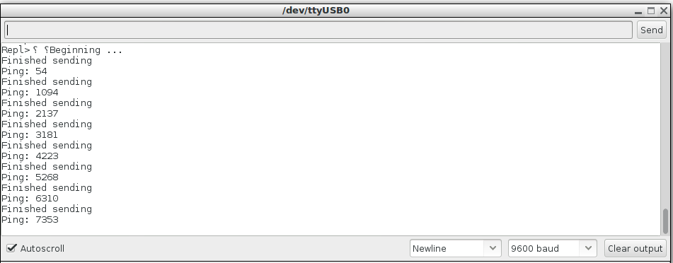
Basically, when you serial read the Client board, you see the Ping, so the time (in ms) that it make to send a signal, be seen by the Server board and transmit back to the Client.
It's suppose to be something like 40ms. But here, the time is bigger and bigger each loop with or without the nF24 plugged:
 So I decided to make something else for this assigment.