Electronic Design
The assigment page
The goal of this week was to learn an electronic design software and design my own board.
First things first
I had to choose a software. Everyone in the lab (excluding Henk) is using Eagle. So I downloaded it from Autodesk website and install it.
On Linux it's a simple folder to unzip with an executable in it.
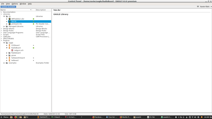
I also had to install the Fab Eagle library. I downloaded it and put it in the "lbr" folder in the Eagle folder. Fastoche.
Eagle
I launched Eagles. The control panel appears. It's where you manage your project and your librairies.
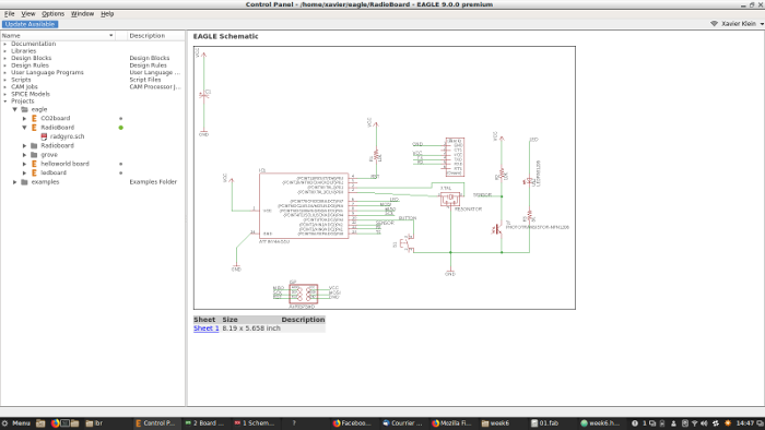
To use your libraries, open libraries and the lbr tabs. Right-click on it and select use. A green circle have to appears if it's good.
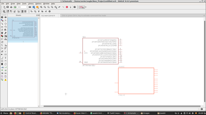
After that, time to create a new project. Click on File->New->Project. Name it and Right-click->New->Schematic. A new window appears, the Schematic design interface.
This interface allows you to make schematics, an hum, schematic view of your PCB. There's a lot of icons who correspond to tools here but I only used shortcut (just by typing the command):
Add = to add a new object from the library
Net = to start a net wire (the connections)
Move = move objects
Delete = delete objects
Name = name the objects and nets. When you're naming to net extremity with the same name, they're connected.
Value = add a value to the object
Label = label the object
Info = get information about the object
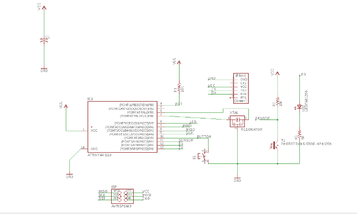
For this assigment we have to make an Echo-Hello-World board. The basic one is like this:
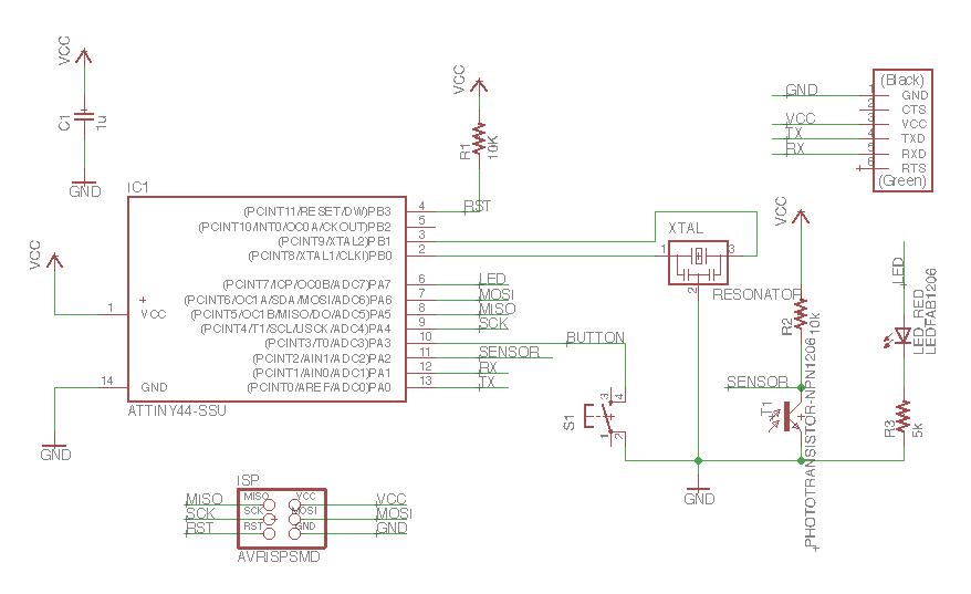
It has an Attiny44, a 6 pins header for programming with the FabISP, a flat 6 pins header for FTDI communication, a 10k resistor for the Reset pin (it prevents the device to reset randomly), a capacitor (to disable the automatic reset upon serial connection) and a resonator.
The resonator is here to have a precise, external clock. The ATTINY84 has an internal clock but it can be innacurate. The resonator has 3 pins. 2 pins, XTAL1 and XTAL2 on pin 2 and 3 of the Attiny44, the other one to ground (GND), pin 14.
We had to add 3 more elements: a button (input), a LED (output), a phototransistor (so a second input device for sensing light).
Buttons are basic components used to open or close manualy the circuit. Here, we plugged it to Attiny's pin 10 for reading its state (if its pushed or not). The button we had has 4 pins:
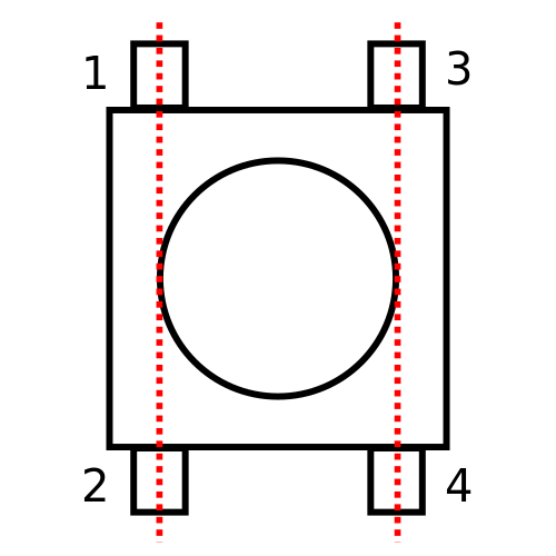
When you don't touch it, current can flow through pins 1 and 2 and pins 3 and 4. Pin 1 and pin 2 are not connected to pin 3 and 4
But when you press the button, pins 1 and 2 are now connected to pin 3 and 4:
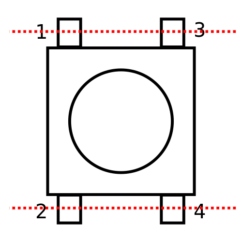
For this board we used only 2 pins, pins 1 and 3. Pin 3 is connected to Attiny's pin 10 (for reading its state) pin 1 is connected to GND. Some component are plugged after pin 1.
To have some feedbacks, we put also an LED. This component products light when current flows on it. It's polarized. Current comes from pin 6 (configure as an output pin) and after flowing in the LED, go to GND.
So there's a green mark on the SMD LED who's showing the GND side. Finally, we had to put a resistor. VCC is 5V and most of the time LED can't handle it. It will works a couple of minutes and the LED will fry.
So I had to do some researchs to know which resistor to add to the circuit. Part numbers are: 160-1167-1-ND. I googled it and find the datasheet.
To know resistor value, I went on this website. I needed 3 infos:
-Source voltage: 5V from USB.
-Diode forward voltage: according to digikey it's 1.8V.
-Diode forward current (mA): according to the datasheet: 40mA.
The website tells me to put a 82 Ohms resistor. But there's no such resistors at Waag so I used the smallest, a 499 Ohms resistor.
Photo transistor has to be first powered with VCC, before current flows in the compenent, we putted a 10k resistor who's acting like a pull-up resistor. The pull-up resistor is a way to be sure that the state of the component is HIGH or LOW and not something in between (floating state).
To read those states you need to plugged it to one of the Attiny44 pins. This component is polarized, there's a mark of one the sides, VCC come by this side. Finally, we plugged to the button to control it.
Here's the schematic:
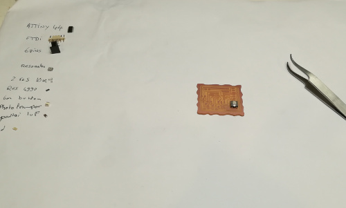
Here's what I needed:
6-pin header
Microcontroller ATtiny44A
FTDI header
20MHz resonator
2x Resistor (10k)
Resistor (value unknown till I calculate for the LED)
Button (6mm switch)
LED (red)
Phototransistor
Capacitor (1uF)
Ground
VCC
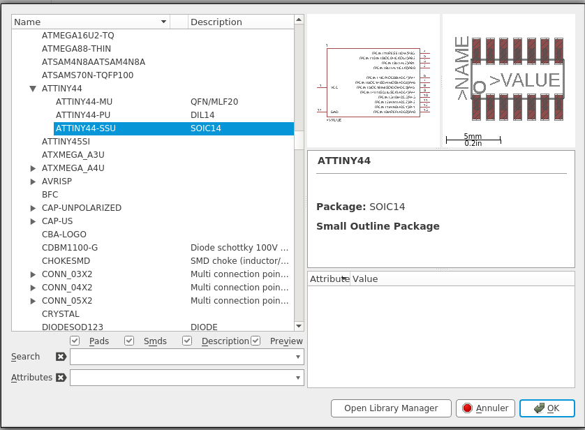
So I typed "Add" and this menu showed up. I searched for the Fab folder:
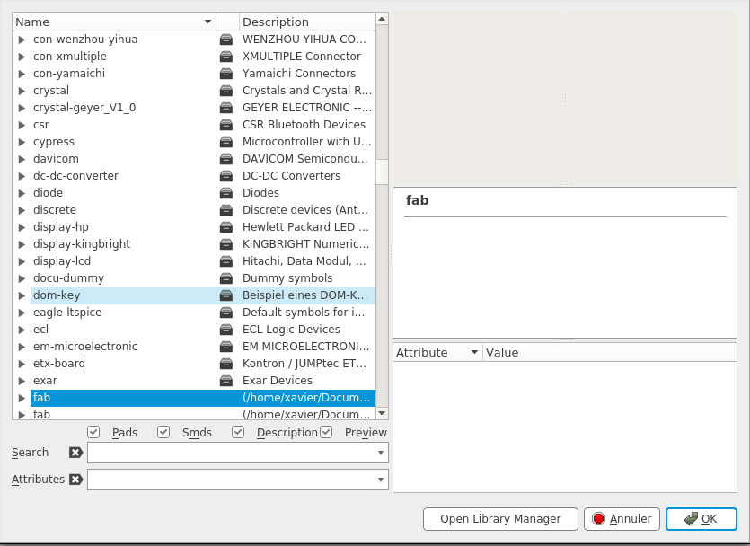
Inside it, I found one of the parts, for exemple the ATtiny44A, click on it and press OK. I choose where to put it and press Escape to come back to the ADD menu.
I did it for all the parts. After that I just had to use "Net" and "Name" commands to connect the parts:
Before designing the board, I clicked on the ERC button to check if there's no problems. There was no problem.
So now it's time to switch to the board. Click on the dedicated button (File -> Generate/Switch to board) to enter in Board mode.
In Board mode, you have to design the pcb for real. You have to organize all parts and draw the route between. In order to do that, I used some new shortcuts:
Route: route the traces
Ripup: ripup a route
Ratsnest: clean up the airwires
Rotate: rotate the selected part
Move: move the selected part
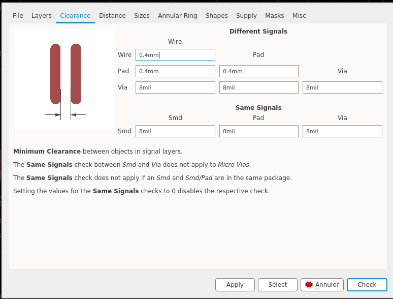
Before drawing I had to set design rules. Click on the DRC button on the toolbar. This menu open, I selected the "Clearance" tab and putted 0,4mm everywhere because I know that my endmill is 0,4mm diameter.
I started to draw my traces. Design rules are here to tells you when a trace isn't possible because of the size of your endmill.
After a lot of redraw (there's always a route impossible to make) I managed to have this (thanks to Johanna).
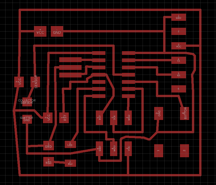
I use the DRC menu to check if there's any problems. No problem.
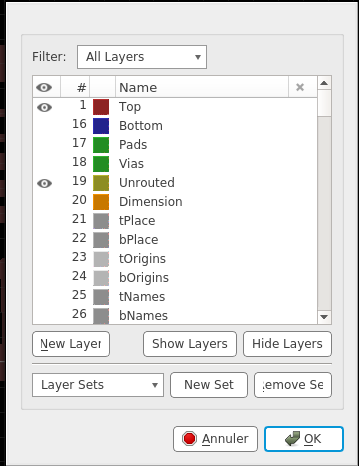
I used the Layer menu to select only the Top traces:
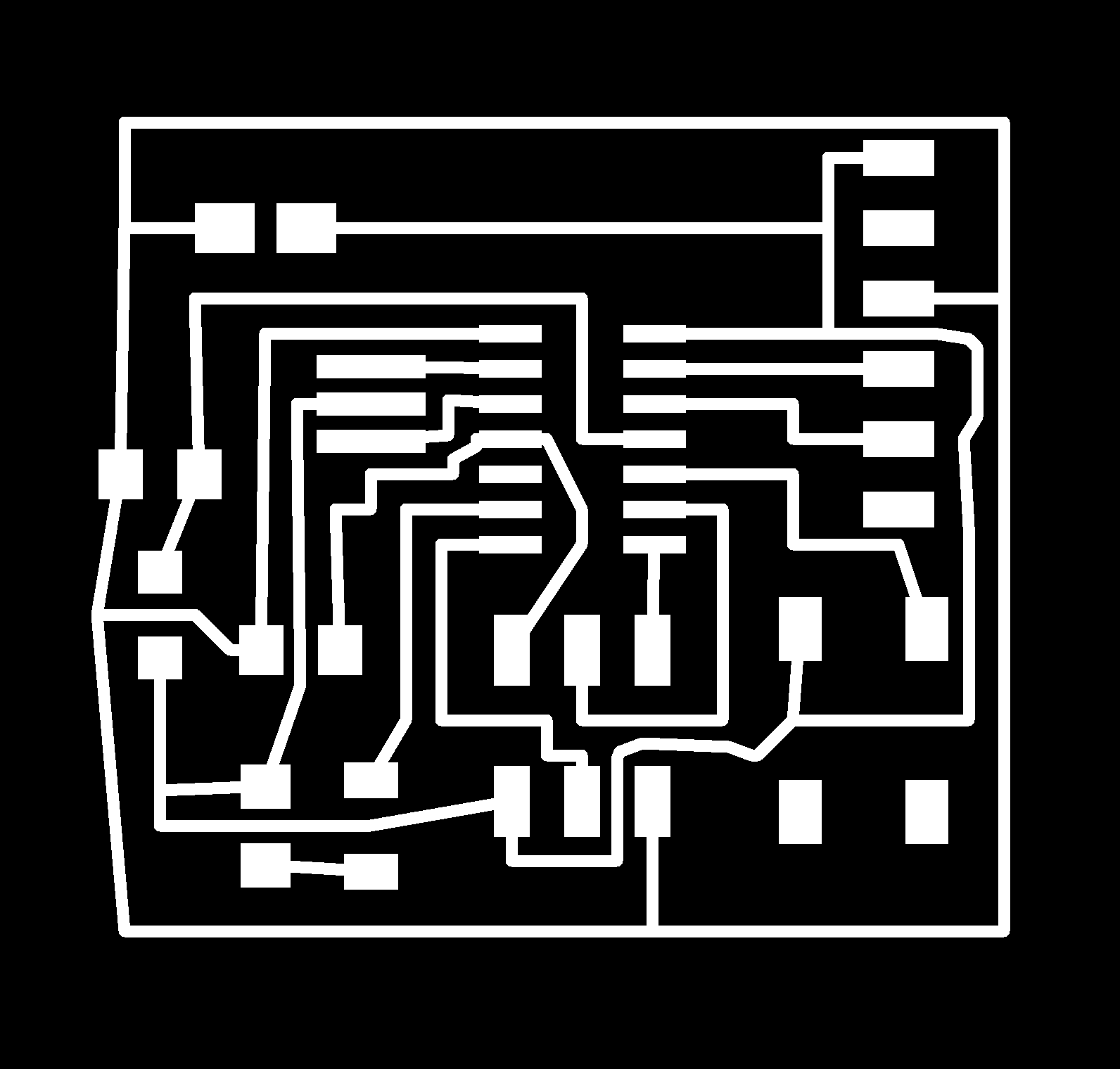
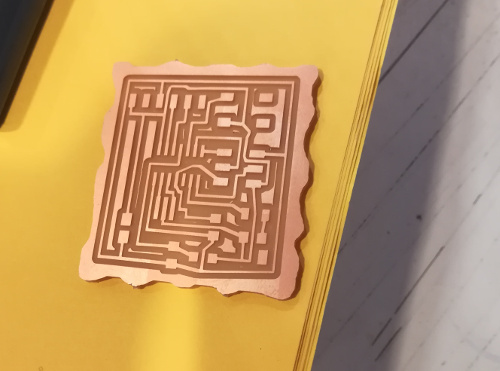
I finally export the board in png. File -> Export -> Image
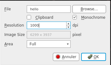
I checked Monochrome and put 1000 Dpi. I obtained this:
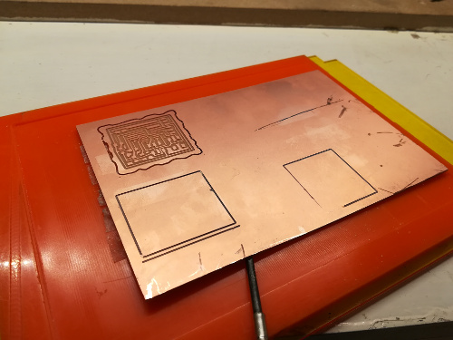
In Gimp, simply using the pencil, I draw this bottom layer:

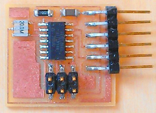
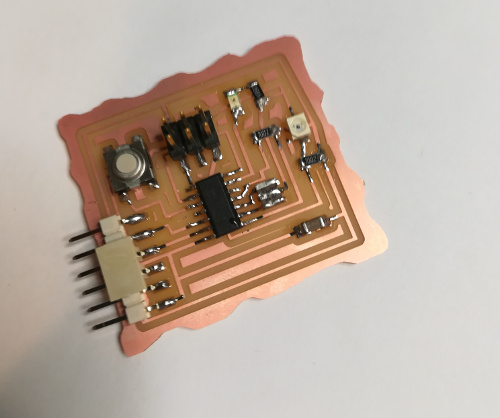
Using the same settings than Electronic Production week, I milled the board and soldered the part:
To see if it work, I checked if is there's a communication between the microcontroller and my computer.
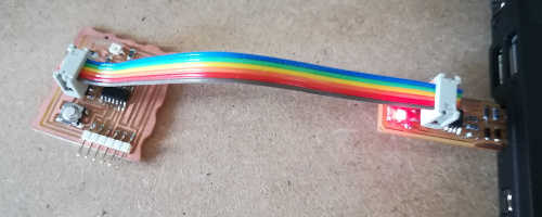
I take my FabISP, and plugged the 6 pin cable into the 6 pin header. I Plugged the other side to my new board.
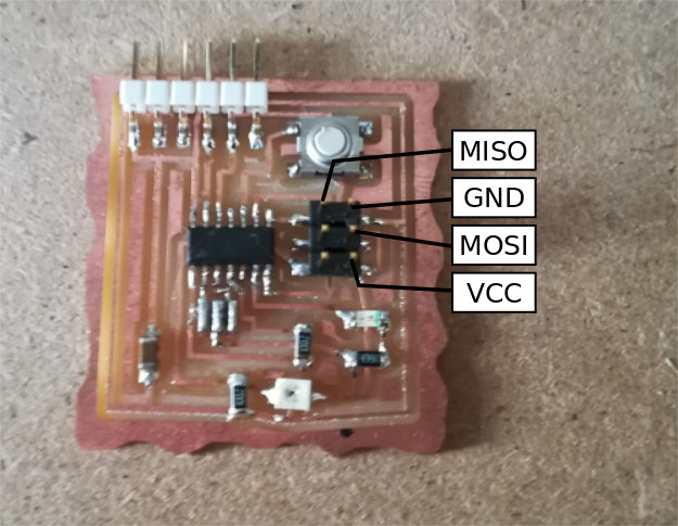
I watched out that FabISP's pins connect to the correct one on the board:
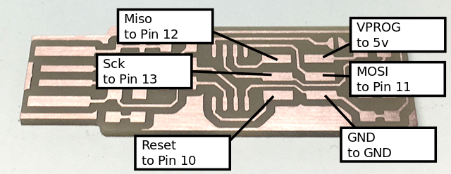
The result once connected:
I openned my terminal and enter this command:
avrdude -c usbtiny -p t44
If the result is:
avrdude: AVR device initialized and ready to accept instructions
Reading | ################################################## | 100% 0.01s
avrdude: Device signature = 0x1e9207 (probably t44)
avrdude: safemode: Fuses OK (E:FF, H:DF, L:FE)
avrdude done. Thank you.
It works ! Now it can be programmed!