Electronics Production
The assigment page
The goal of this week was to make a board, Brian's FabTinyISP, with a little milling machine, solder components on it and flash the firmware.
I really enjoyed discovering this topic, it feels like I have new powers!
⇝ Milling the board ⇝ Programming the board with an Arduino
Technical overview
There's several ways to make a board, but milling it in a copper plate seems to be a good way to do it. It seems to be fast and reliable.
This week we learnt how to use a small milling-machine, the Roland "Modela" MDX20.
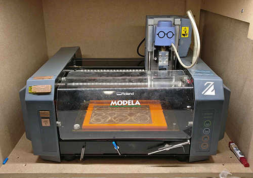
Useful Modela's specs:
-XY table size: 220 mm (X) x 160 mm (Y)
-Max operating aera: 203.2 mm (X) x 152.4 mm (Y) x 60.5 mm (Z)
-Max table load weight: 1000 g
-External dimensions: 476.8 mm (W) x 381.6 mm (D) x 305 mm (H)
Schematic I found in the user manual:
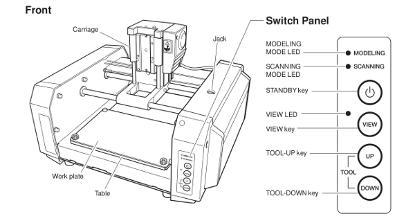
-Standby is used to turn off the machine.
-View mode put the table in the front and stop the tool. Usefull for placing your plate or changing the end mill.
-Up & Down allows you to move the tool on Z axis in order to make the Z zero or moving the tool without touching your work.
Push the two and the machine erase its memory. It's usefull if the machine tries to continue cutting something who's still in memory.
For this mill, we use 2 end mill: A 1/64 for traces, a 1/32 for cutting.
This machine is controlled by a dedicated computer, using Mods.
How to mill the board
1. The first thing to do is placing the copper plate on the table. Press view to let the table going in the front. XO and YO are at the bottom-left of the table.
2. I release the table by removing the 2 screws. I putted some double-face tape on the face without copper in order to stick to the table. I putted the table back.
I placed the end mill by loosen the collar using an allen wrench and push it in until the head of the end. I pressed view to come back in operating mode.
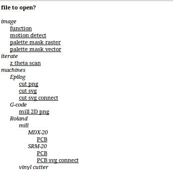
3. In the computer, I used the shortcut to connect to Mods. On this page, I selected "Open Server Program".
and here, PCB in the MDX's menu:
This screen will prompt:
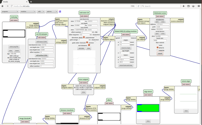
Here, you make all the settings for the machine:
-Read png- Select an high-resolution black and white png (at least 1000dpi).
-Set Pcb default- Select if it's tracing and cutting and the size of the tool.
-Mill Raster 2D- Select tool diameter, offset number, don't touch path merge and click calculate. It will generate the path.
-Roland MDX-20 etc- You can control the machine with this menu using the move to origin menu.
-WebSocket serial- Select Open to connect with the machine after launch the connection script in the desktop.
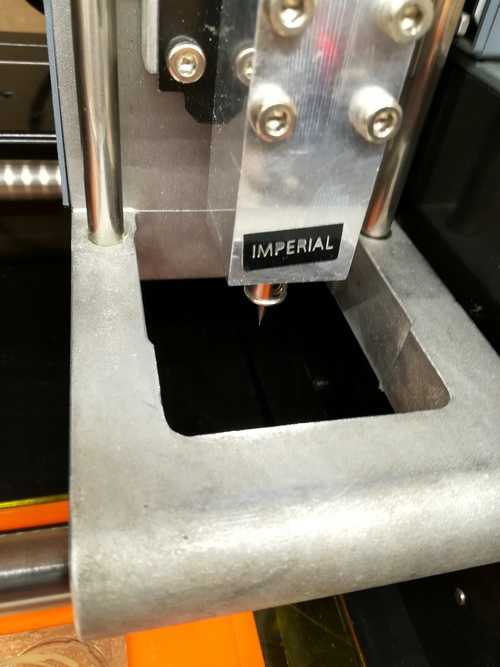
Now I had to make the Z0. Using the Move to origin command, I placed the end mill above my origin. I wrote somewhere origin's coordinates.
With the wrench, I loosen the collar and get down the end mill till it touched the copper. I spinned around a bit to remove the dust and tighten the collar.
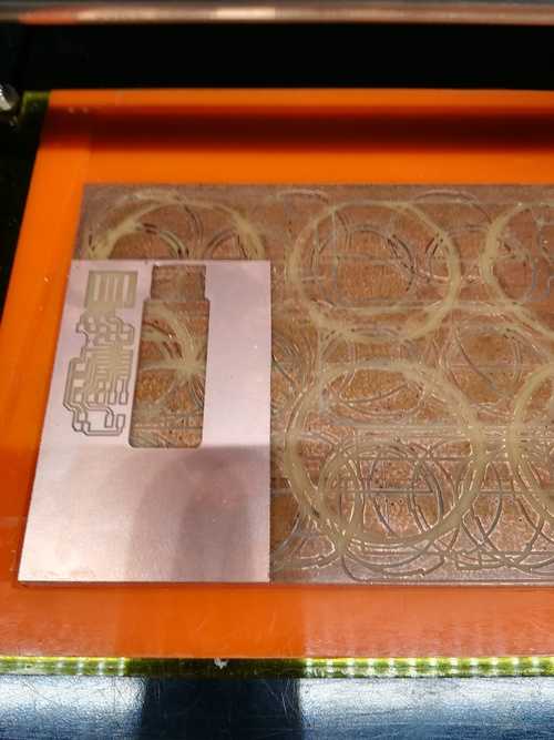
To start, I repressed calculate and Send File.
You have to use two files.
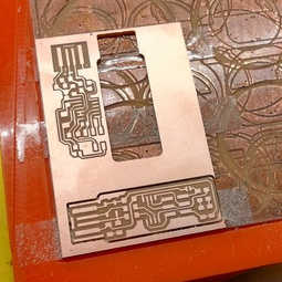
The first one it's for the trace and use a 1/64 end mill:

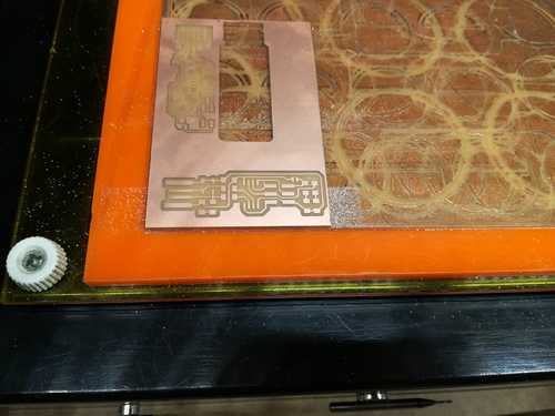
The second one it's for cutting out the board and use a 1/32 end mill:

How to solder the component
First things first, you have to wash the board with soap in order to remove the fat.
Fix your board with some double-face tape on a A4 sheet. The board will be easier to manipulate.
I took those components:
-1x ATtiny85
-2x 1kΩ resistors
-2x 499Ω resistors
-2x 49Ω resistors
-2x 3.3v zener diodes
-1x red LED
-1x green LED
-1x 100nF capacitor
-1x 2x3 pin header
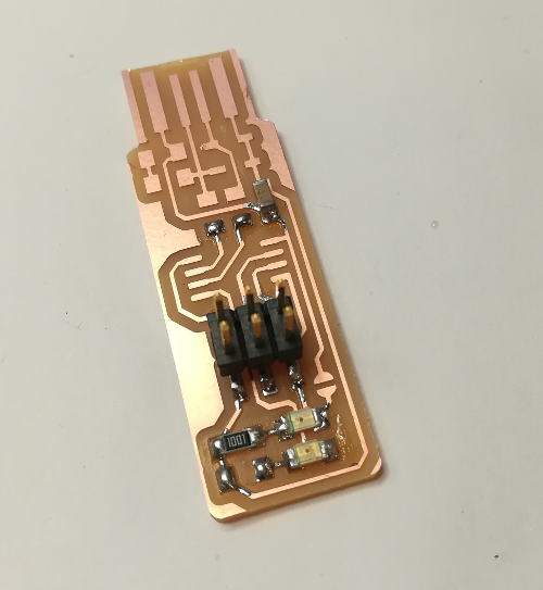
I followed Brian's schematics and started to solder the components on my board.
Here's how to solder a component:
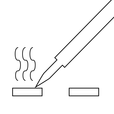
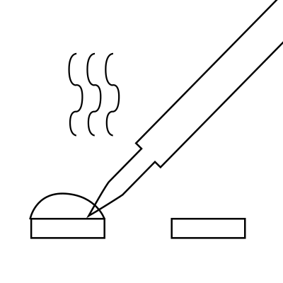
Heat one the 2 pads. Come with a bit of tin and heat it on the pad. When there's is enought tin, it forming a ball.
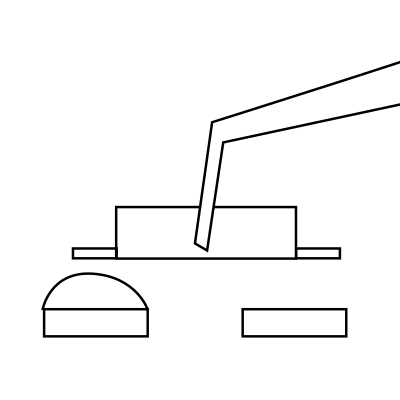
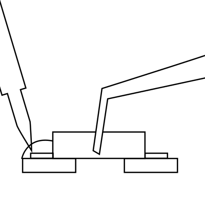
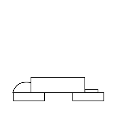
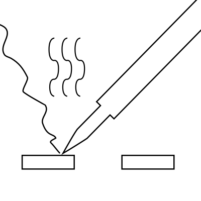
Take your component with an electronic special tweezer. Heat the tin ball and put the component into the melted tin. When the tin covers both the pad and the component's contact, remove your iron.
Heat the second pad AND the component's contact. Put some tin, it suppose to melt naturaly and make a beautiful joint. Remove the tin and move away you iron.
If your first solder is not well done, try just heat it with the iron. Put some more tin if you think it's necessary. It's done!
My soldering order:
-2x3 pins.
-2 LEDs with their resistor.
-2 diodes, resistors and capacitor.
-the attiny85.
I forget to solder the jumper, so when I try the board in the computer the first time there's no red LED.
I forget also to cover the USB pins with tin. I think I was very excited.
Emma did a quick test, the board seemed to work, let's programm it!