Networking and communications
The assigment page
Design and build a wired &/or wireless network connecting at least two processors.
⇝ Making boards ⇝ Programming ⇝ Second making boards ⇝ Second programming
This week I want to make a foot switch triggered by the gyroscope on another board. I tested first with a momentary swith some weeks ago:
So here the concept: If the gyro is moving then trigger the rythmbox.
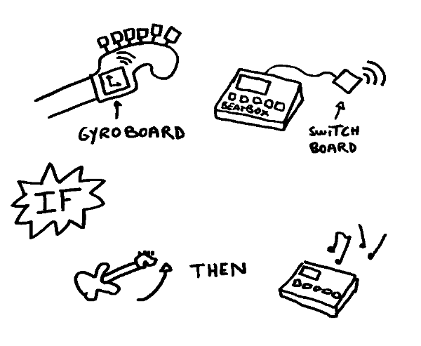
Ok. A footswitch is basicly a switch and if the button is pressed, the circuit is closed and then it's trigerring the rythmbox. So I need to send some current into the rythmbox.
My machine it's an Alesis SR-16 who's working with 9V. To be sure, I made this little circuit and mesure how many volt is using for the switch. 3.3V. So it's perfect, my boards will be powered with 3V batteries.

And I tested with the "Blink" exemple to control the machine. It's 5V then, but it didn't seems to be a problem, the blinking is very short:
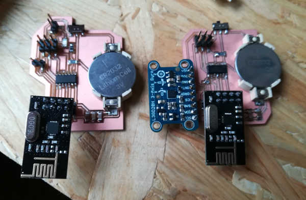
I need 2 boards. One on the guitar with the gyro and one who will be plugged to the machine and control it. Those boards will be powered with 3v button batteries.
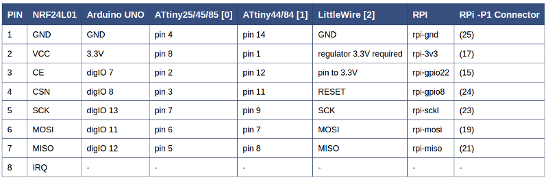
I'm using an RF24 radio component. I checked on the Arduino library where to connect its pins on an Attinny84 HERE.
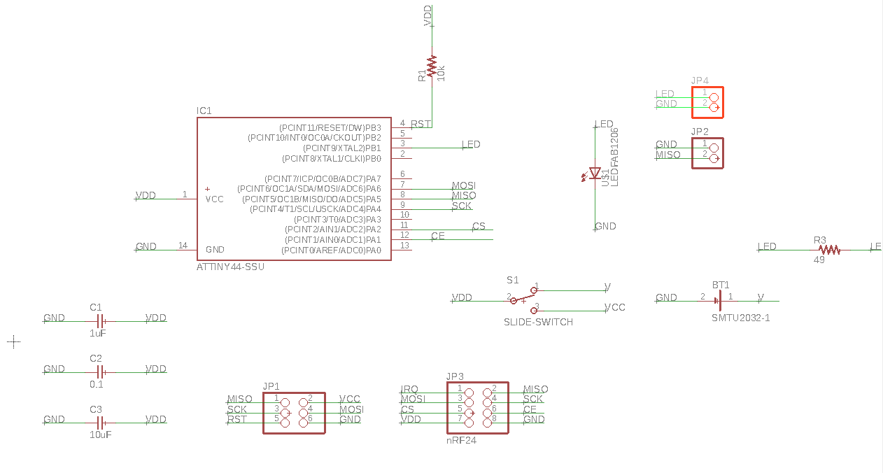
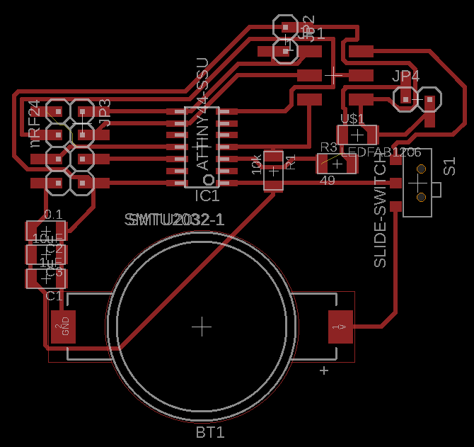
Here the schematics and traces for the first board (gyro):
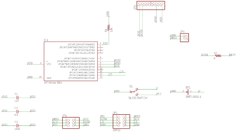
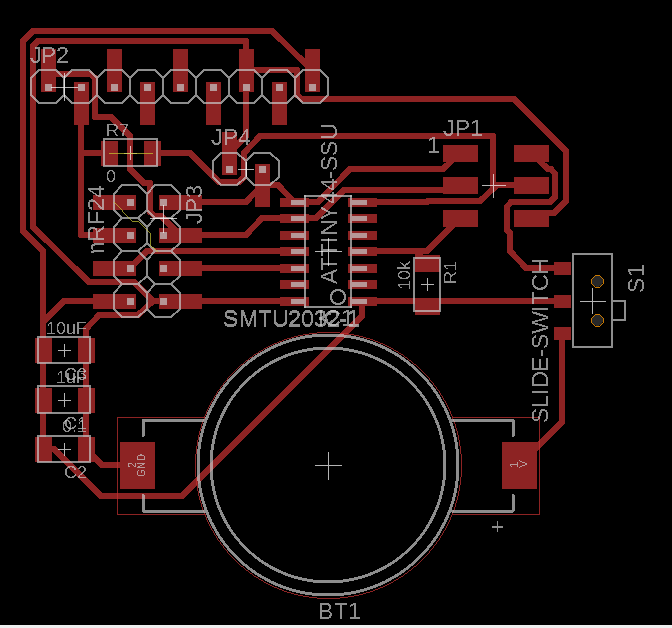
Components:
- Attiny84A
- Slide switch
- 9 pins headers
- 2 pins headers
- 6 pins headers
- 8 pins headers
- 10k resistor
- 1 0 ohm resistors
- 3 capacitor: 1uF, 0.1, 10uF
- Renata SMTU-2032-1 battery holder (footprints)
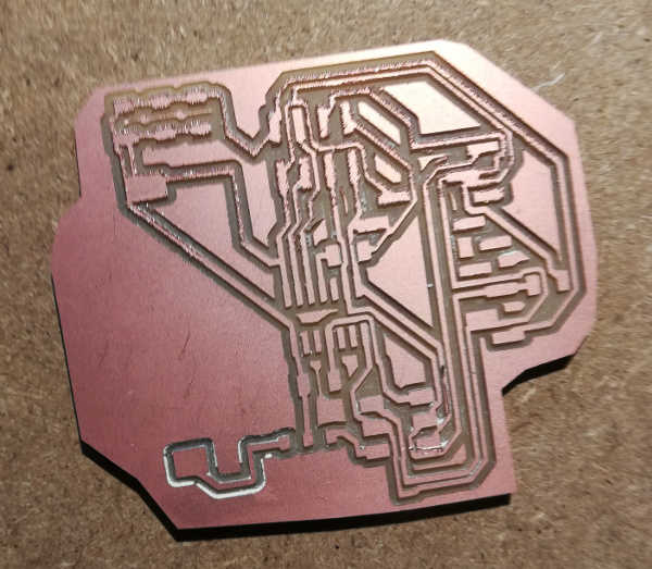
I try to mill this board but the result was no good, with a lot of traces who was not milled:
And here's the schematics and traces for the second board:
Components:
- Attiny84A
- Slide switch
- 2 2 pins headers
- 6 pins headers
- 8 pins headers
- 1 red led
- 2 10k resistor
- 3 capacitor: 1uF, 0.1, 10uF
- Renata SMTU-2032-1 battery holder (footprints)
A bit of avrdude -c usbtiny -p t84. My boards are reconized.
I tested first the gyro board with my old gyro-plexy.ino. It worked.
I test the second one with this code:
NOW TIME TO CODE