Networking and communications
The assigment page
Design and build a wired &/or wireless network connecting at least two processors.
⇝ Making boards ⇝ Programming ⇝ Second making boards ⇝ Second programming
Making I2C communication boards
The radio never works. So I have to find another thing to do. I chose I2C because in my Input device week I used a gyroscope which use I2C.
So I'm used to SCL and SDA pins. The goal is to use an Attiny85 to communicate with another. The master one tells the slave to makes an LED to blink.
I2C communication according to Sparkfun I2C is:
For making the boards, I used Eagle as usual. I used this website to know how to wire all the stuff.
So I made 2 boards. The master is a basic board with an Attiny85 and 2 pins for I2C communication. The slave one is the same but with an red LED and its resistor.
For I2C communication, you have to use 2 dedicated pin, you can find it on the datasheet:

SDA (data) is pin 5 and SCL (clock) is pin 7. The same than MOSI and SCK. You have to put some pull-up resistors between pins and VCC too.
Master board
Components:
-Attiny85
-1uF Capacitor
-3 1k resistor
-1 2x6 pins header
-1 2X2 pins header
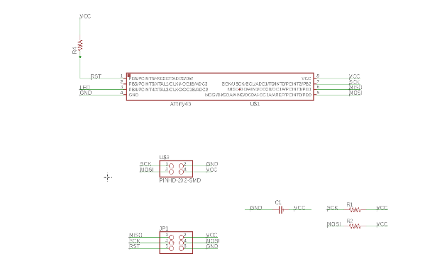
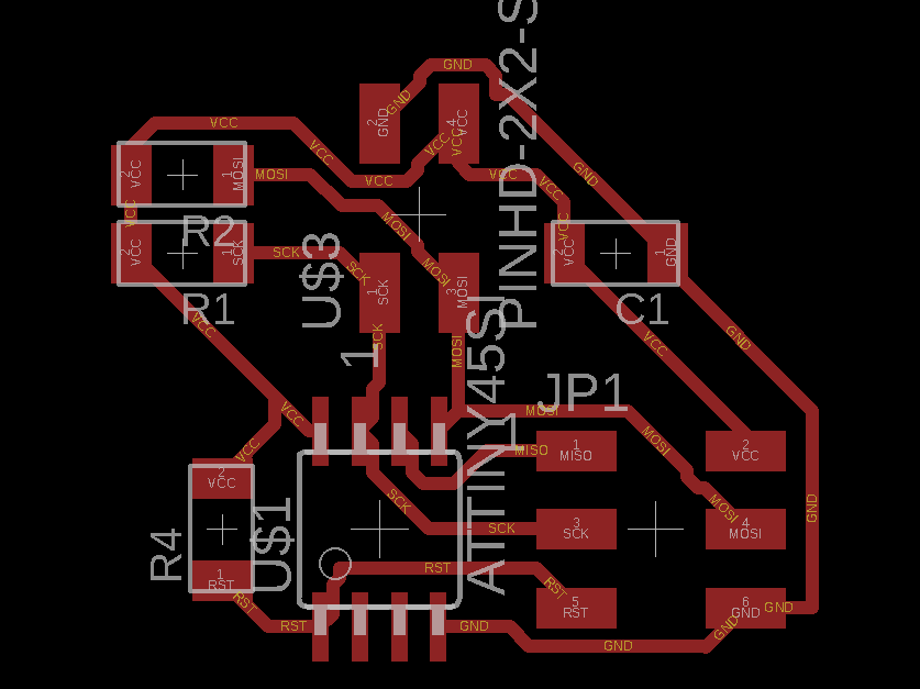
Slave board
Components:
-Attiny85
-1uF Capacitor
-3 1k resistors
-1 499 Ohm resistor
-1 red LED
-1 2x6 pins header
-1 2X2 pins header
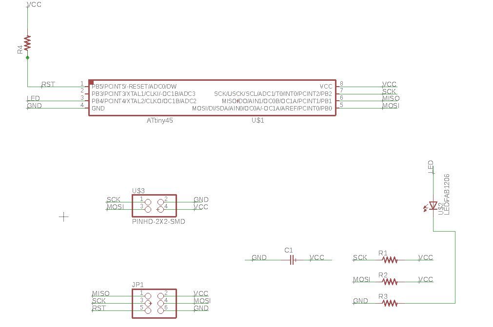
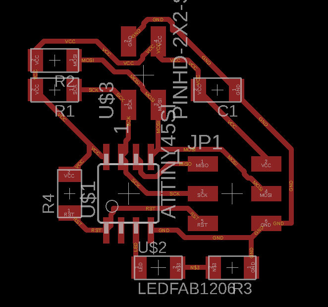
I milled the boards, I had some incidents (the sheet moves) so I had to cut the boards by hands:

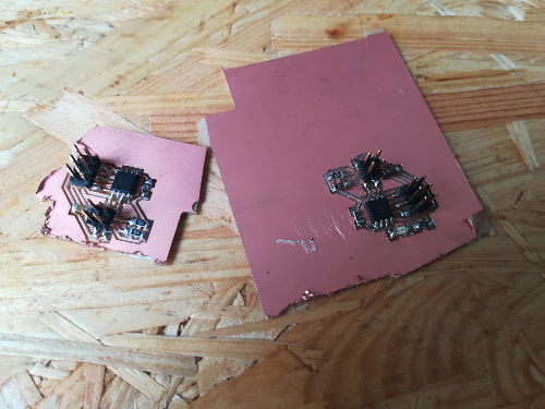
So it's a couple of ugly boards, there's a lot of shorts but it's worked at the end after testing the boards with avrdude -c usbtiny -p t85.
TIME TO CODE, eventually.