FINAL PROJECT
⇝ First presentation ⇝ Project Development ⇝ Electronic ⇝ Programming ⇝ The clamp ⇝ The enclosure
Download unsuccessfull RF24 boards Eagle files
Download the succefull wired-gyroscope Eagle files
Making the radio boards
In the
Networking and communications week I tried to make 2 boards communinate using the radio transceiver
nF24.
I failed because there's differents libraries, who's not using the same Attiny84 pinout between each other so I thought that in the confusion, I made something wrong.
We know that Martin Risseeuw
succeed to get the nF24 works for communication between 2 Attiny84 (I need a 84 because of the number of pins, gyro needs 4 as the nf24).
So I design 2 boards following exactly Martin's pinout:
// ATMEL ATTINY84 / ARDUINO
//
// +-\/-+
// VCC 1| |14 GND
// SerialTx (D 0) PB0 2| |13 AREF (D 10)
// (D 1) PB1 3| |12 PA1 (D 9)
// RESET PB3 4| |11 PA2 (D 8)
// PWM INT0 (D 2) PB2 5| |10 PA3 (D 7) CE
// SS/CSN (D 3) PA7 6| |9 PA4 (D 6) USCK
// USI-DI (D 4) PA6 7| |8 PA5 (D 5) USI-DO
//
So I design 2 boards (they're pretty the same boards with a different pinout than
Networking and communications week).
One with the gyro:
-1 Attiny84
-1 0.1uF Capacitor
-1 10uF Capacitor
-3 0 Ohm resistors
-1 10k resistor
-1 2032 battery holder
-1 slide-switch
-1x9 pinheads (for gyro)
-1x2 pinheads (for serial)
-2x4 pinheads (for nF24)
-2x6 pinheads (for programming)
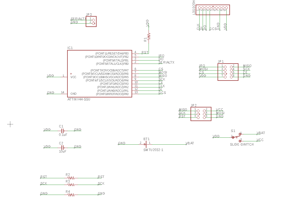
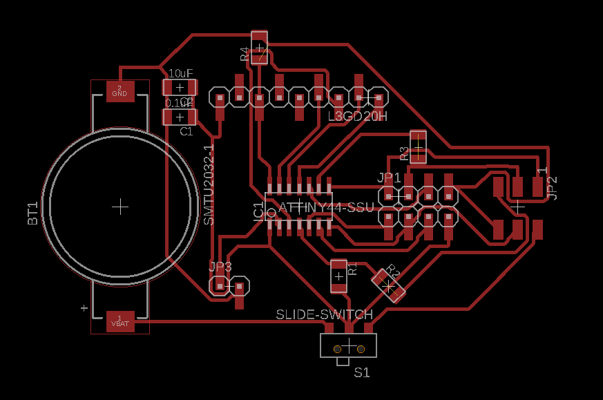
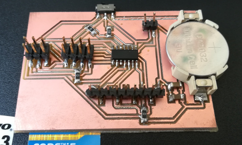
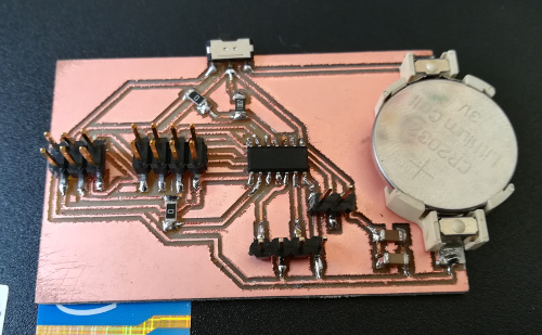
The board after milling it and solder the components:
The other one with just 2 outputs pins:
-1 Attiny84
-1 0.1uF Capacitor
-1 10uF Capacitor
-2 0 Ohm resistors
-1 10k resistor
-1 2032 battery holder
-1 slide-switch
-1x4 pinheads (for outputs)
-1x2 pinheads (for serial)
-2x4 pinheads (for nF24)
-2x6 pinheads (for programming)
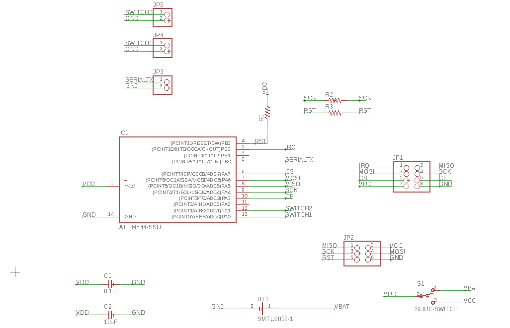
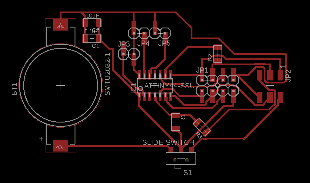
The board after milling it and solder the components:
I tested it with the regular
avrdude -c usbtiny -p t84 and they works!
Programming the radio boards
So now I have the good boards with the good pinout, it's time programming. To avoid conflict between libraries, versions, etc, I tried on another computer with Arduino 1.5.
I downloaded
this library.
I downloaded
this Arduino Tiny Core.
And I put this code from Martin's page in one of the board:
Ping Client
/*
* repo : https://github.com/stanleyseow/arduino-nrf24l01/
* Author : Stanley Seow
* e-mail : stanleyseow@gmail.com
* date : 8 Aug 2013
* Edited by : By Martin on 5 may 2014
Some default values to take note when using this mirf/spi85 library
Uses Mirf forked library from https://github.com/xdarklight/arduino-nrf24l01
- node addressing is similar to RF24 libs but the bytes are flipped
byte TADDR[] = {0xe3, 0xf0, 0xf0, 0xf0, 0xf0}; will matches receiver node of RF24 below
const uint64_t pipes[2] = { 0x7365727631LL, 0xF0F0F0F0E3LL };
The repo for the RF24 lib is at https://github.com/stanleyseow/RF24/
*/
#include <SPI85.h>
#include <Mirf.h>
#include <MirfHardwareSpi85Driver.h>
#include <nRF24L01.h>
// This USI was defined in SPI85.cpp
// Not to be confused with SPI (MOSI/MISO) used by ICSP pins
// Refer to page 61 of attiny84 datahseet
//
//#define USI-DO 5
//#define USI-DI 4
//#define USCK 6
#define CE 7
#define CSN 3
// ATMEL ATTINY84 / ARDUINO
//
// +-\/-+
// VCC 1| |14 GND
// SerialTx (D 0) PB0 2| |13 AREF (D 10)
// (D 1) PB1 3| |12 PA1 (D 9)
// RESET PB3 4| |11 PA2 (D 8)
// PWM INT0 (D 2) PB2 5| |10 PA3 (D 7) CE
// SS/CSN (D 3) PA7 6| |9 PA4 (D 6) USCK
// USI-DI (D 4) PA6 7| |8 PA5 (D 5) USI-DO
// +----+
int bufferSize = 0;
char buffer[32] = "";
unsigned int counter = 0;
uint8_t nodeID = 0;
void setup(){
Serial.begin( 9600 ); // for tiny_debug_serial
Mirf.cePin = CE;
Mirf.csnPin = CSN;
Mirf.spi = &MirfHardwareSpi85;
Mirf.init();
/*
* Configure reciving address.
*/
Mirf.setRADDR((byte *)"clie1");
/*
* Set the payload length to sizeof(unsigned long) the
* return type of millis().
*
* NB: payload on client and server must be the same.
*/
Mirf.payload = sizeof(unsigned long);
/*
* Write channel and payload config then power up reciver.
*/
/*
* To change channel:
*
* Mirf.channel = 10;
*
* NB: Make sure channel is legal in your area.
*/
Mirf.config();
Serial.println("Beginning ... ");
}
void loop(){
unsigned long time = millis();
Mirf.setTADDR((byte *)"serv1");
Mirf.send((byte *)&time);
while(Mirf.isSending()){
}
Serial.println("Finished sending");
delay(10);
while(!Mirf.dataReady()){
//Serial.println("Waiting");
if ( ( millis() - time ) > 1000 ) {
Serial.println("Timeout on response from server!");
return;
}
}
Mirf.getData((byte *) &time);
Serial.print("Ping: ");
Serial.println((millis() - time));
delay(1000);
}
And I put this one in the other board:
Ping Server
*
* repo : https://github.com/stanleyseow/arduino-nrf24l01/
* Author : Stanley Seow
* e-mail : stanleyseow@gmail.com
* date : 8 Aug 2013
* Edited by : By Martin on 5 may 2014
Some default values to take note when using this mirf/spi85 library
Uses Mirf forked library from https://github.com/xdarklight/arduino-nrf24l01
- node addressing is similar to RF24 libs but the bytes are flipped
byte TADDR[] = {0xe3, 0xf0, 0xf0, 0xf0, 0xf0}; will matches receiver node of RF24 below
const uint64_t pipes[2] = { 0x7365727631LL, 0xF0F0F0F0E3LL };
The repo for the RF24 lib is at https://github.com/stanleyseow/RF24/
*/
#include <SPI85.h>
#include <Mirf.h>
#include <MirfHardwareSpi85Driver.h>
#include <nRF24L01.h>
// This USI was defined in SPI85.cpp
// Not to be confused with SPI (MOSI/MISO) used by ICSP pins
// Refer to page 61 of attiny84 datahseet
//
//#define USI-DO 5
//#define USI-DI 4
//#define USCK 6
#define CE 7
#define CSN 3
// ATMEL ATTINY84 / ARDUINO
//
// +-\/-+
// VCC 1| |14 GND
// SerialTx (D 0) PB0 2| |13 AREF (D 10)
// (D 1) PB1 3| |12 PA1 (D 9)
// RESET PB3 4| |11 PA2 (D 8)
// PWM INT0 (D 2) PB2 5| |10 PA3 (D 7) CE
// SS/CSN (D 3) PA7 6| |9 PA4 (D 6) USCK
// USI-DI (D 4) PA6 7| |8 PA5 (D 5) USI-DO
// +----+
int ledPinRed = 10;
int ledPinGreen = 8;
int ledPinBlue = 1;
int bufferSize = 0;
char buffer[32] = "";
unsigned int counter = 0;
uint8_t nodeID = 0;
void setup(){
Serial.begin( 9600 ); // for tiny_debug_serial
Mirf.cePin = CE;
Mirf.csnPin = CSN;
Mirf.spi = &MirfHardwareSpi85;
Mirf.init();
pinMode(ledPinRed, OUTPUT);
pinMode(ledPinGreen, OUTPUT);
pinMode(ledPinBlue, OUTPUT);
Mirf.setRADDR((byte *)"serv1");
/*
* Set the payload length to sizeof(unsigned long) the
* return type of millis().
*
* NB: payload on client and server must be the same.
*/
Mirf.payload = sizeof(unsigned long);
/*
* Write channel and payload config then power up reciver.
*/
Mirf.config();
digitalWrite(ledPinRed, HIGH);
digitalWrite(ledPinBlue, HIGH);
digitalWrite(ledPinGreen, HIGH);
Serial.println("Listening...");
}
void loop(){
/*
* A buffer to store the data.
*/
byte data[Mirf.payload];
/*
* If a packet has been recived.
*
* isSending also restores listening mode when it
* transitions from true to false.
*/
if(!Mirf.isSending() && Mirf.dataReady()){
Serial.println("Got packet");
/*
* Get load the packet into the buffer.
*/
Mirf.getData(data);
if (data[0] == '1') {
digitalWrite(ledPinRed, LOW);
digitalWrite(ledPinBlue, HIGH);
digitalWrite(ledPinGreen, HIGH);
}
else if (data[0] == '2') {
digitalWrite(ledPinRed, LOW);
digitalWrite(ledPinBlue, LOW);
digitalWrite(ledPinGreen, HIGH);
}
else {
digitalWrite(ledPinRed, LOW);
digitalWrite(ledPinBlue, LOW);
digitalWrite(ledPinGreen, LOW);
}
/*
* Set the send address.
*/
Mirf.setTADDR((byte *)"clie1");
/*
* Send the data back to the client.
*/
Mirf.send(data);
/*
* Wait untill sending has finished
*
* NB: isSending returns the chip to receving after returning true.
*/
Serial.println("Reply sent.");
}
}
Basically, when you serial read the Client board, you see the Ping, so the time (in ms) that it make to send a signal, be seen by the Server board and transmit back to the Client.
It's suppose to be something like 40ms. But here, the time is bigger and bigger each loop with or without the nF24 plugged:
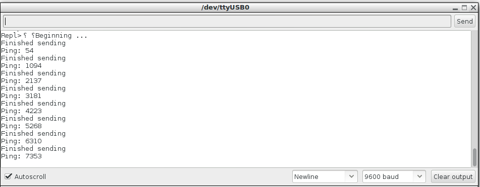
So now I think I lost enought times with radio and make my final project wired.
Designing a board for wired connections
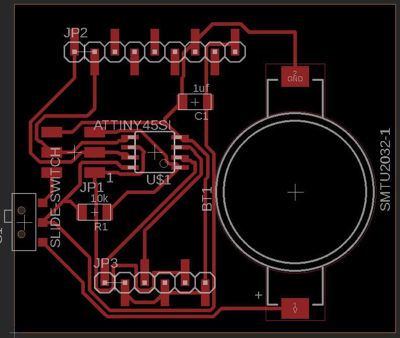
To comfort myself I told me that is rare to have wireless communication between "music things". Perhaps because of the risk of latency. So I designed a board in Eagle:
Components used:
- Attiny85 microcontroller
- L3GD20H 3 axis gyroscope
- Slide-switch
- CR2032 battery holder
- 1 10k resistor
- 1 1uF capacitor
- 2X6 pins header
- 1x6 pins header
Beside of the gyroscope it's a very simple board.
I've take an Attiny85 because I didn't need so much pins and it's more reliable than the 84 in term of compatibility with Arduino's libraries.
The gyro is the one I've already used in
Input week and
Interface and Application Programming week. It uses I2C communication and it's reliable (check
Networking week for more info about I2C).
For power I used 3.3V CR2032 battery because it's small and don't need so much juice.
The slide-switch allows to on-off the device and to programm the board (where you put some 5V form USB) without to have to remove the battery each time.
The resistor is for the reset pin. The capacitor to disable the automatic reset upon serial connection.
2X6 pins header for programming the board through ISP and 1x6 for the output pins.
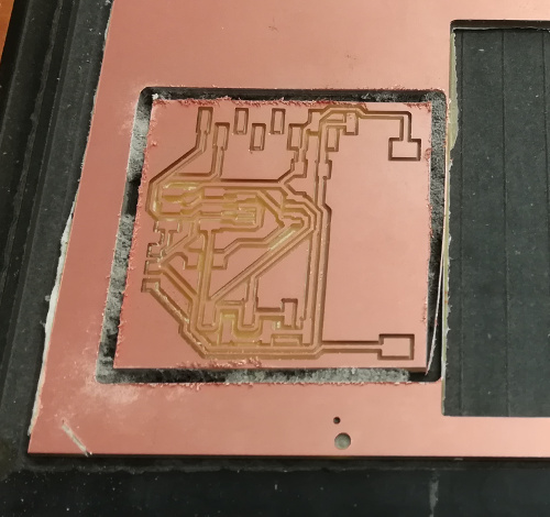
Schematic and board:
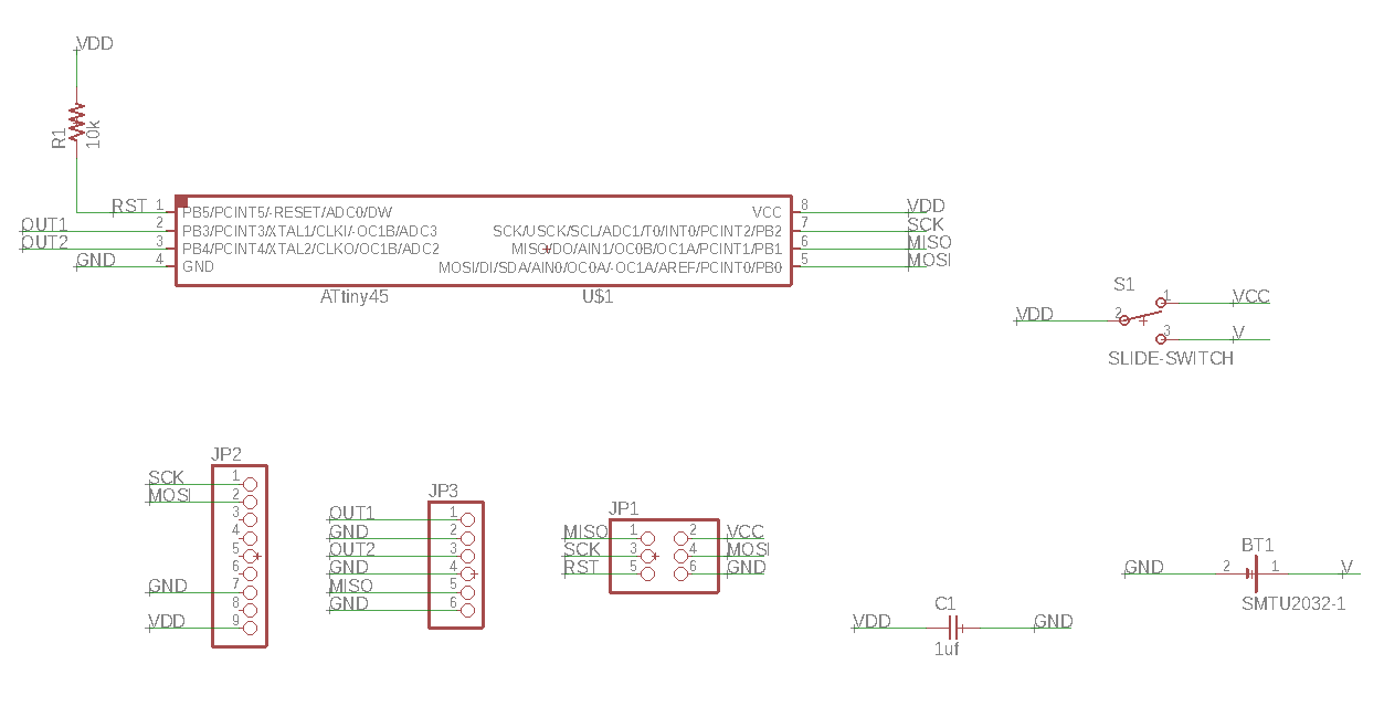
I milled it as usual with no problem and soldered the component.
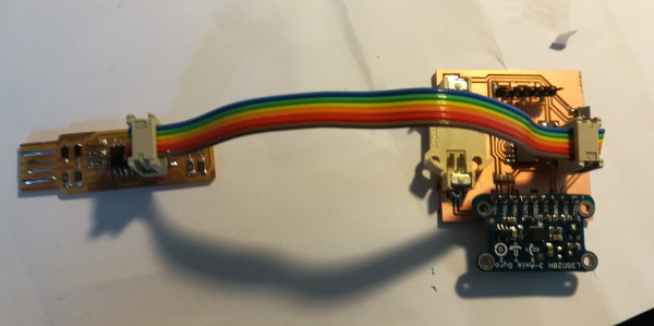
I tested with
avrdude -c usbtiny -p t85 and it works!
Time to code.