⇝ First presentation ⇝ Project Development ⇝ Electronic ⇝ Programming ⇝ The clamp ⇝ The enclosure
Download the Fusion360 files, STL and DXF.
Making of the output's enclosure
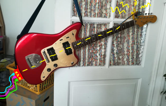
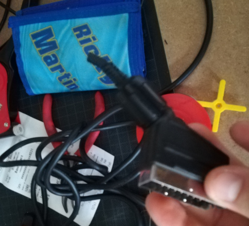
So there's the part with the gyroscope but you have a second part where the cable ends up to a device where you can plug your 6.5mm jack:
I want to make a basic box where the cable from the gyro ends to 3 female jack. And I want to use the strap button to fix it to the guitar.
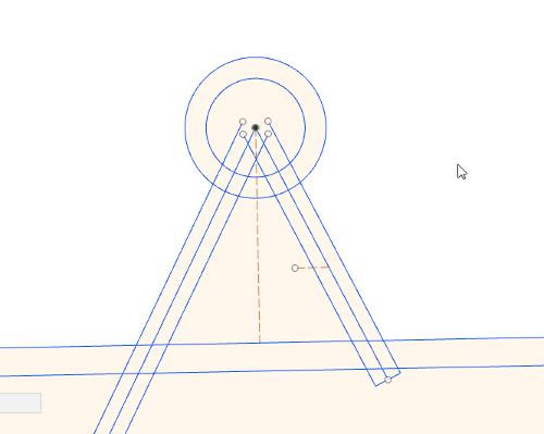
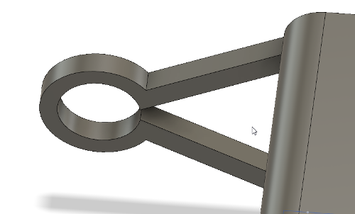
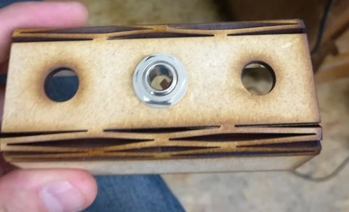
So in Fusion I modeled a test holder and extrude it for 2mm:
I printed it:
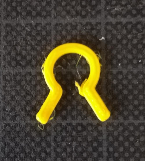
And it worked!
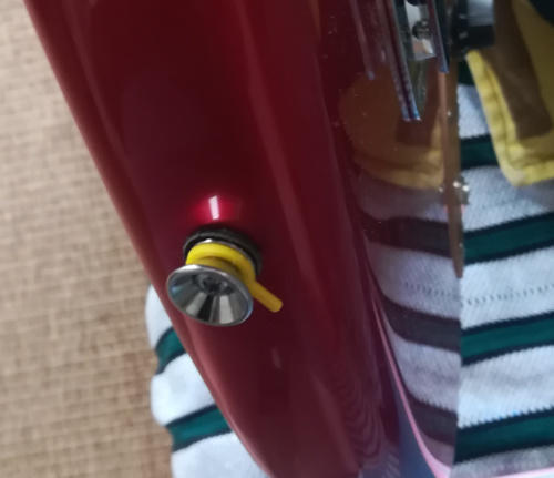
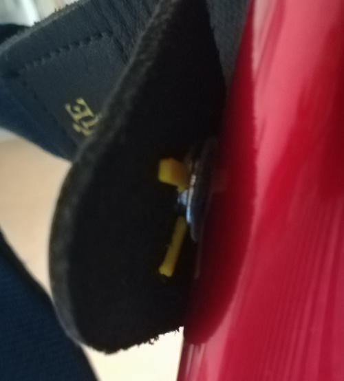
Critical point, the holder have to be thin enought for having the strap in the same time, it's working.
So now I have to make the enclosures for the three jack outputs. It's a simple box:
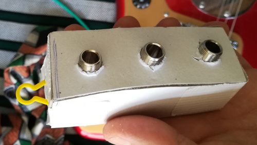
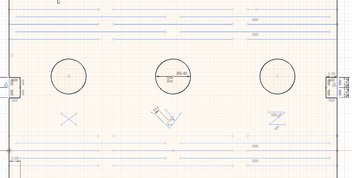
But simple press-fit boxes are not allowed so I add a flexible part. I modeled it in Fusion360. I did a first test, 5 rows, for each edge, I also some holes for the jacks:
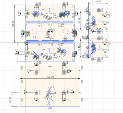
I lasercutted it using Imal's lasercutter. I did like always. I used 3mm MDF with those settings:
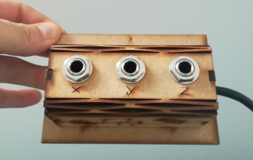
So I designed the other sides, write some infos on and the bottom:
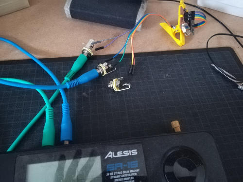
I took an old peritel cable, I cutted it and used 6 of its 9 cable inside to connect jacks with the clamped part. I soldered the cable on the jack (1 output and one GND, jack aren't polarized ) and the other side on a connector (1 output, 1 GND, 1 output, 1 GND, 1 output, 1 GND):
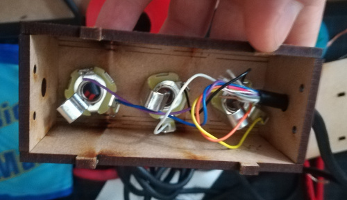
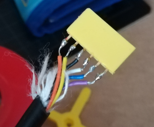
Red/Orange -> Z axis
White/Black -> Y axis
Blue/Violet -> X axis
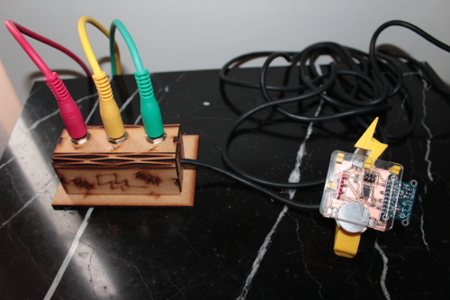
And here the result:
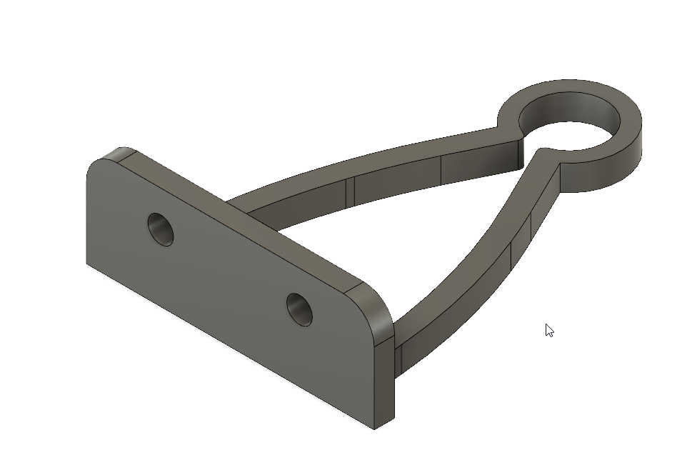
And the strap fixer? I modeled a final version on fusion360, print it and fix it with 2 screws, I've cutted some 2,5mm holes for it:
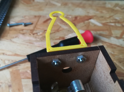
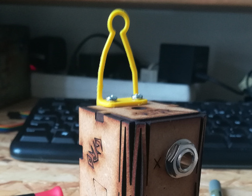
But it's too flimsy and the box can't stop moving when you use it, so, it will be on the ground.
And here a pic of all these things assembled: