Basically, the gyro sends 3 datas for each 3 axis. The datas are values expressed in DPS (degrees per second). So when a specific DPS is reached, it's triggering a little 3.3V pulse through the selected output pin.
There's 3 pins, one for each axis.
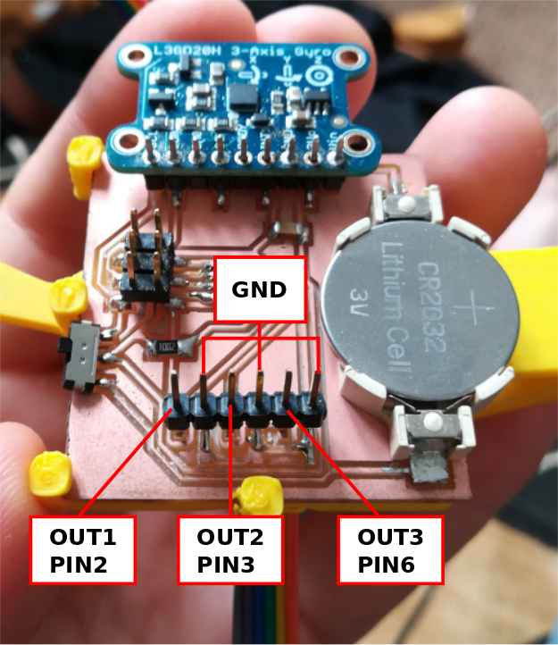
according to datasheet:
-Out1 Z axis, pin2 is digital 3, set as output.
-Out2 Y axis, pin3 is digital 4, set as output.
-Out3 X axis, pin6 is digital 1, set as output.
So there's the code I used so far:
#include <Wire.h> //Allows I2C com using SDA and SCL pins.
#include <Adafruit_L3GD20.h> //Loading sensor's library.
Adafruit_L3GD20 gyro; //Naming sensor
#include <SoftwareSerial.h> // SoftwareSerial allows serial com with Attiny
#define rxPin 0
#define txPin 5
SoftwareSerial serial(rxPin, txPin);
int OUT1 = 3; //
int OUT3 = 1; //
void setup()
{
serial.begin(9600);
pinMode(OUT1, OUTPUT);
pinMode(OUT3, OUTPUT);
// Try to initialise and warn if we couldn't detect the chip
if (!gyro.begin(gyro.L3DS20_RANGE_250DPS)) //You can choose your range here by comment/uncomment
//if (!gyro.begin(gyro.L3DS20_RANGE_500DPS))
//if (!gyro.begin(gyro.L3DS20_RANGE_2000DPS))
{
serial.println("Oops ... unable to initialize the L3GD20. Check your wiring!");
while (1);
}
}
void loop()
{
gyro.read();
serial.print("X: "); serial.print((int)gyro.data.x); serial.print(" "); //Data's serial prints
serial.print("Y: "); serial.print((int)gyro.data.y); serial.print(" ");
serial.print("Z: "); serial.println((int)gyro.data.z); serial.print(" ");
delay(100);
if (gyro.data.z > 60) //It's this threshold you have to set. Highter is it, speeder you have to move the guitar. Make some test.
{
digitalWrite(OUT3, LOW); // turn the X output to LOW to be sure there's no mismatch
digitalWrite(OUT1, HIGH); // turn the Z output for 10ms, it's enough to trigger the rhythmbox.
delay(10);
}
else
{
digitalWrite(OUT1, LOW); // turn the LED on (HIGH is the voltage level)
digitalWrite(OUT3, LOW); // turn the LED on (HIGH is the voltage level) //nothing happens.
}
if (gyro.data.x > 70)
{
digitalWrite(OUT1, LOW);
digitalWrite(OUT3, HIGH);
delay(10);
}
else
{
digitalWrite(OUT1, LOW); // turn the LED on (HIGH is the voltage level)
digitalWrite(OUT3, LOW); // turn the LED on (HIGH is the voltage level)
}
}
This code is set for 2 pins, so 2 movements. I plugged 2 pins of the board to my rhythmbox. X axis is for play/stop function, Z is for launching breaks and change patterns: