Mechanical and machine design
For the upcoming two weeks we are going to team up and create a working machine! Sounds like huge challenge since I never thought that I’m going to construct the working machine in my life!
I teamed up with: Coral, Carolina and Eve.
Coral created a website where we’ve merged our documentations: http://barcelonamachines.fabcloud.io/group3/
She also created a cool video which is showing the process of creating:
We are four people in the group so it won’t get messy each one was mainly focusing on one task, but still taking part in consulting and supporting others.
For me the task will be: take care about electronics (connections between the boards, motors and the battery) + programming.
Schedule and tasks:
We have two weeks. First one is ment to be mostly for working on mechanical desig, second - for machine design. As I’ve mentioned before we are four people, each one will be focusing on main task and supporting the others. But becouse some tasks can be executed paralelly, we will treat this weekly division (mechanicel/machine design) quite fluently, trying to use the time in the best way.
We are not planning the days exactly but more making to-do list with tasks:
Organsing:
- creating git repository, shared google docs for documentation and folders for files
- brainstorming about the idea for machine
- collecting inspirations
- dividing tasks
- collecting materials and parts
Designing:
- sketching the general structure
- reworking some files that we’ve found on inspirational pages (from previous FabAcademy years), creating addictional ones
- lasercutting the test assamblage in cardboard
- making test for kerf in actual material
- reworking the design after testing
- working on a pen holder
- making a mechanical testwith motors
Electronics:
- exploring Gestalt Nodes
- wiring the boards
- connecting the battery and motors
- testing on example code
- assambling motors and electronics with design and testing
- modifing the code
Assigning the main tasks:
Dorota: electronics and programming Carolina: design and electronics Coral: website, video, design Eva: design, lasercutting
For the mechanical design I’ve took part in first phase which was reaserch and brainstorming. Based on a inspiration from FabLab Ajaccio machine design http://archive.fabacademy.org/archives/2016/fablabajaccio/mtm.html I’ve also created one of the repeatable elements in Fusion 360.
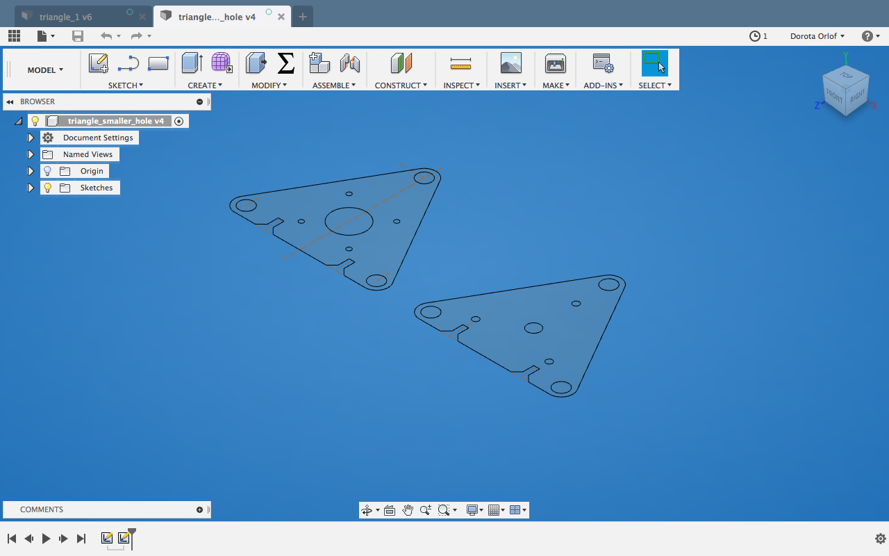
I exported it as a 2D Drawing and retoch (joined the broken lines in Illustrator)
I’ve understood pretty fast that it’s going to be very messy if we all four are going to work on design parts…they have to match each other so will be better to make them in one file. Also with the use of one type of programm (me and Coral are using Fusion 360, Carolina and Eve - Rhino).
I’ve passed the files to Carolina and jumped to my electronics&programming challenge.
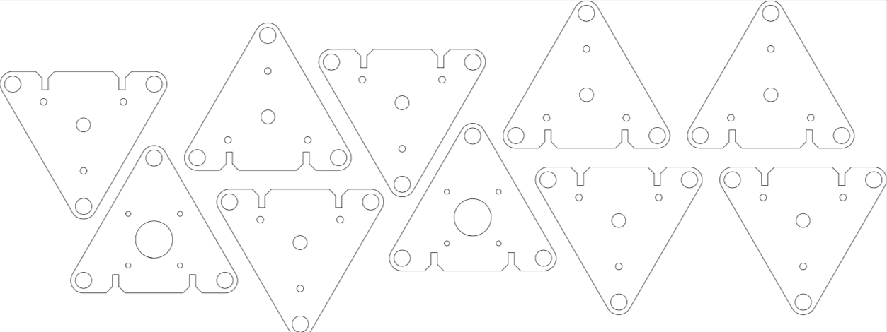
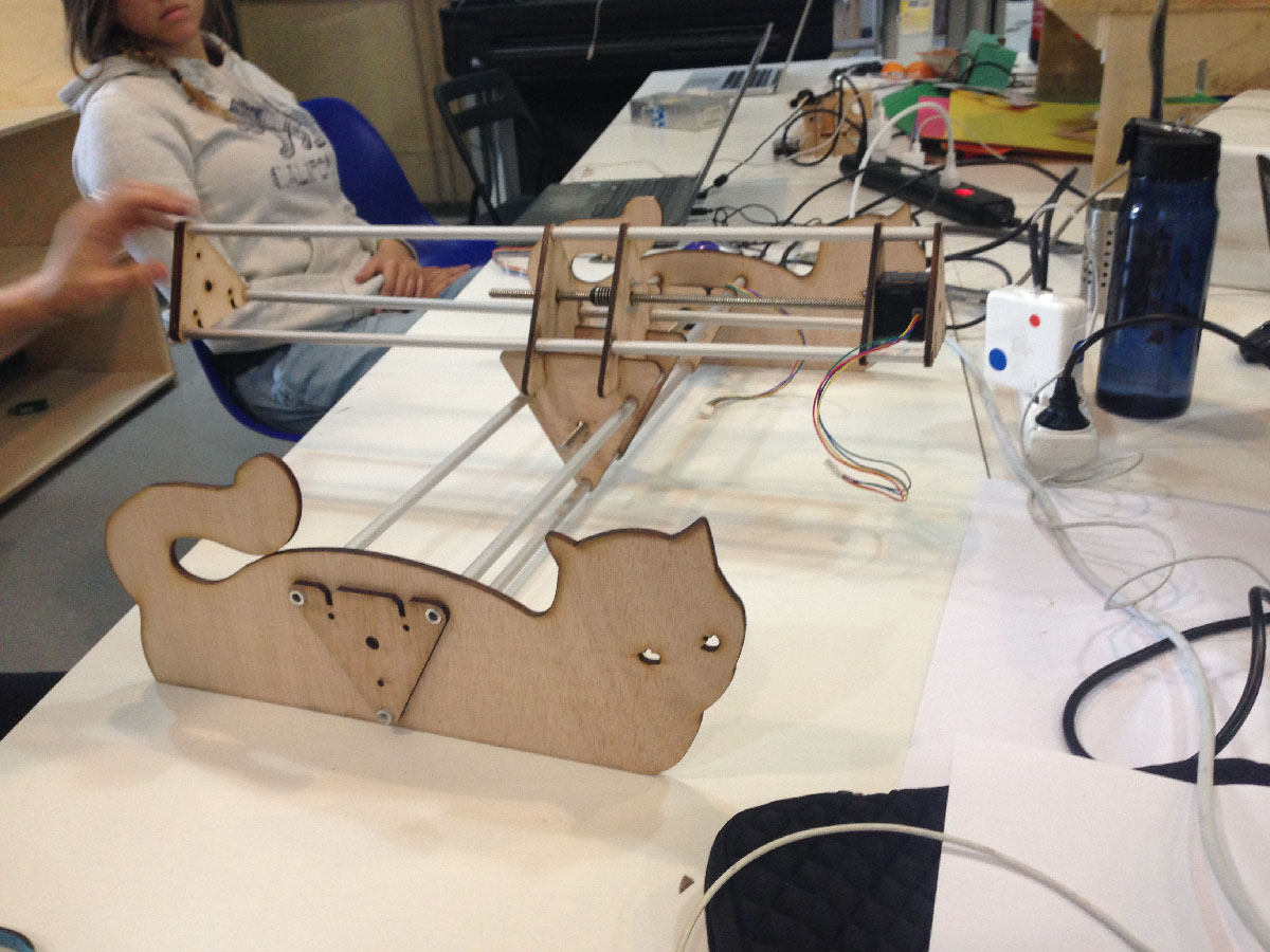
In the meantime, after girls tested and lasercutted the pieces, we’ve assembled the structure to see how everything looks like together. We were also able to test manually the machanism.
Electronics & programming
We are going to use Nadia Peek and James Coleman framework (pygestalt) for modular electronics (Gestalt Nodes) http://archive.monograph.io/james/m-mtm.
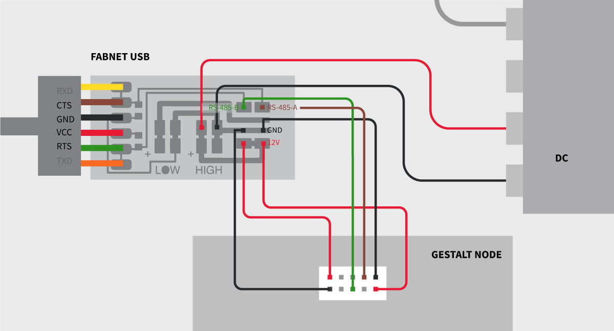
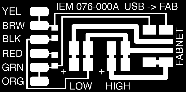
First I wanted to understand the connections between boards, motors, fab usb and battery. We are going to create a cabled network, where components are:
- FABNET-USB - bridge board soldered to FTDI cable to provide power and data to the network
- Gestalt nodes, each for driving single motor
- power supply (12Volts), connected to bridge board
The below schematics shows the connections in a simple way.
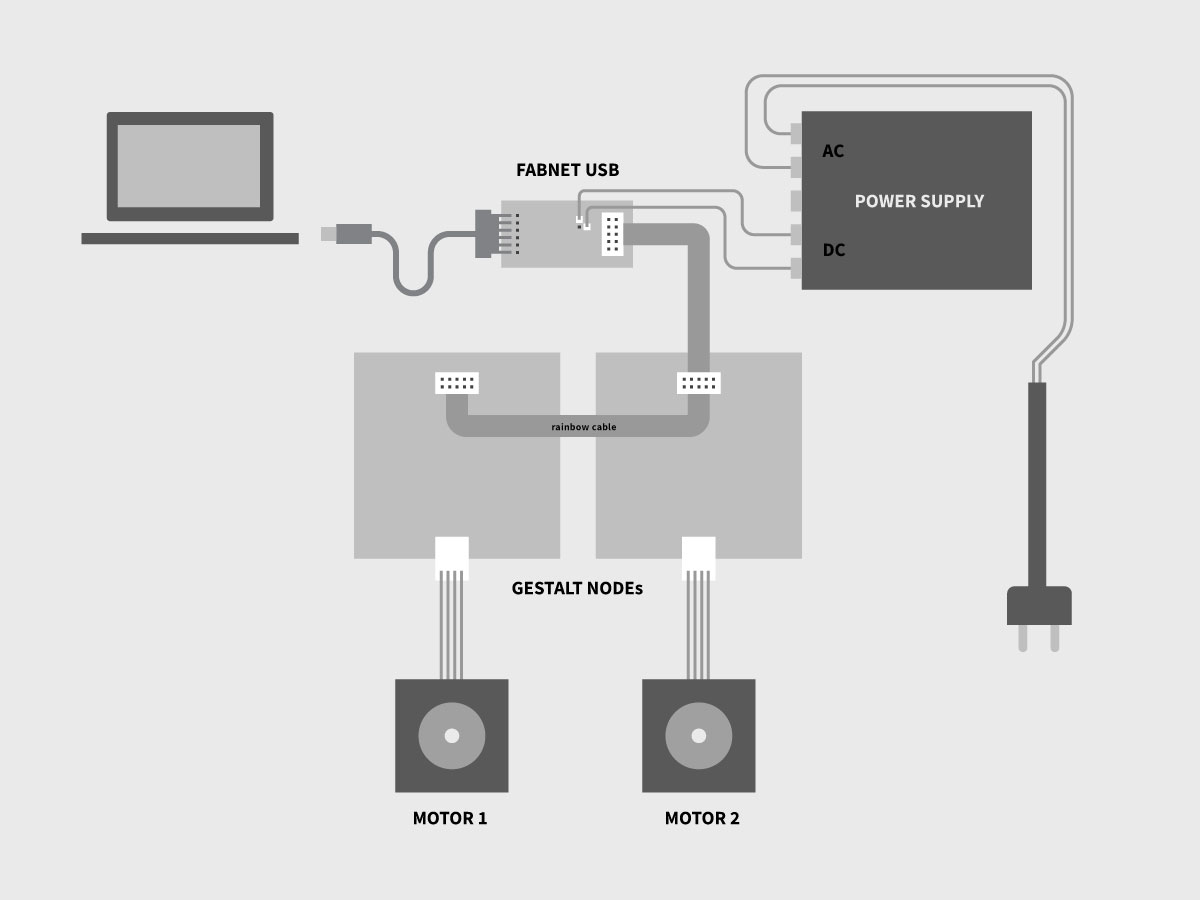
About the FAB NET:
Generally Fabnet is an RS-485 bus (https://en.wikipedia.org/wiki/RS-485) for serial communication system. Multiple receivers can be connected to such a network in a linear, multidrop bus. In our case we are going to connect two motors to drive two axises.
Informations about FabNet: http://mtm.cba.mit.edu/fabinabox/dev/fabnet/overview.html
Motor
We are going to use two stepper motors, each for driving one axis: https://www.amazon.com/STEPPERONLINE-17HS13-0404S1-Stepper-Motor-Printer/dp/B00PNEQ9T4
Battery
We are going to use battery which have output 12 Volts and 2.1 Ampere. Battery is going to transform the alternating current (AC) into direct current (DC) that we need to run our machine. We will get 220 Volts of alternating current from the socket and transform it to 12 Volts of direct current.
For that I had to connect 4 cables to the battery: two coming from the plug with AC (brown, blue), and two getting out to the board with DC (green,red).
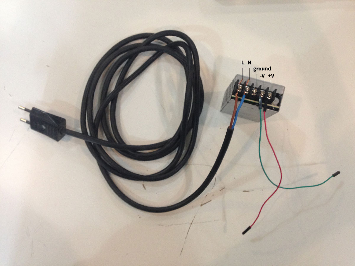
Pay attention:
NEVER HOT PLUG! ( boards should never be powered while connecting). We power the boards at the very end, forgetting this and connecting while powered will most likely destroy the Gestalt Node..
Now we have to connect pins from 8-pin header from FAB NET USB with pins from 10-pin header from geatalt node. Since the components are having different amount of pins we are going to use the cable which at the end is divided (so one can connect the pins in unconventional order).
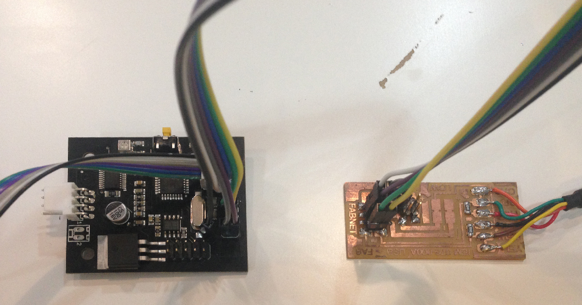
Pay attention:
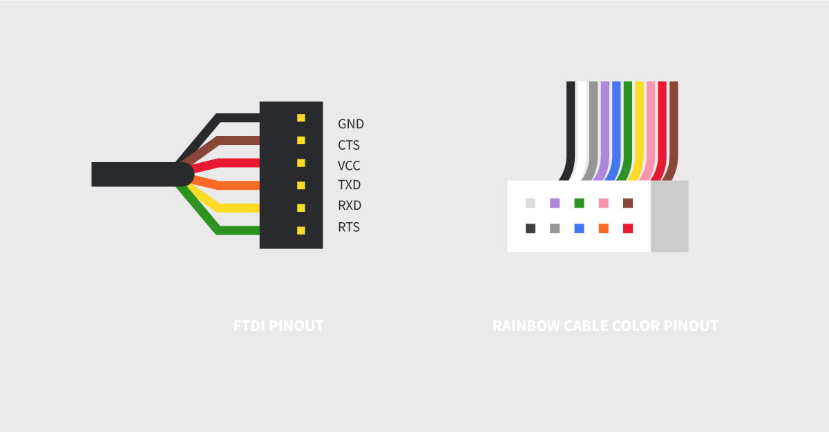
The FTDI cables order is different than ina regular FTDI cable. I guess it’s becouse it creates better composition with traces.
Here for reminding order and pinout of regular FTDI, order of colors of traditional rainbow cable:
We are using ready FABNET USB that we have in FabLab Barcelona, though if one would like to mill on its own, here are the traces:
PROGRAMMING
GESTALT NODE FIRMWARE:
Credits for Kris Rijnieks for writting a helpful README file in the GitHub repository of the firmware! The things got clearer after reading it.
One has to burn the firmware on the Gestalt nodes to work further with axis movement . Firmware is available on GitHub under this link:https://github.com/imoyer/086-005.
You have to download it and go into terminal to the folder which contains makefile.
To burn the firmware on the gestalt board connect all the necessary equipement:
- FAB USB to computer and to the node
- AVI ISP programmer to the node and your computer
- external power supply to FAB USB
Run the Makefile (by running command make in the terminal) for burning makefile on the board and setting up fuses.
PROGRAMMING THE BOARD/S:
We are going to program the boards in Python, with the use of pygestalt library which contains series of examples to control machines.
https://github.com/nadya/pygestalt
To properly install the library follow the README file inside the linked pygestalt git repository.
Once we have the library installed we can run the example codes:
- single_node.py
- xy_plotter.py
In both of the files one important thing is to change the usb-serial port which enables serial communication.
In the terminal you can list usb ports by typing ls /dev/cu. Now you have to copy the port name and place it in portName=

Now we can run the code by using command: python single_node.py
IMPORTANT: to run the example you have to get to the folder which contains it: pygestalt-master/examples/machines/htmaa
For controlling the axises we are using this line:
moves = [[0,10],[0,20],[20,20],[20,0],[0,0]]
where you specify the x and y position [x,y] of each step. The code above will give us the drawing of the square.
The triangle will be:
moves = [[0,20],[20,0],[0,0]]

We were also experimenting with circle drawing. My coding (and math) skills are very basic, so when it appeared that drawing a circle is much more complicated…I’ve got a hand from our instructor Xavi!
For that one would need a formula which will generate the points and put them in the place of coordinates. We have to specify some additional variables like pi, radius, degrees.
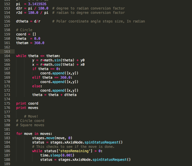
We’ve got the result of circle but with too many points, so the motor was getting a bit crazy and was shaking all the machine. If one would like to polish the code one have to reduce the amount of coordinates.
Python
I’m new to Python, here I’m writting down some code tipps that I’ve gathered during the Python tutorial:
- To install the package (for example pySerial), type in terminal:
sudo pip install pySerial
- To import the package library there are two ways:
from pySerial import *
import pySerial
- To run the code
python myscript.py
installing the git repository directlyy from terminal: git+git://github.com/nadya/pygestalt.git
or download the .zip package, navigate to the folder and: sudo easy_install pygestalt
or run the setup file: sudo python ./setup.py install
INSPIRATIONS:
Nadja: http://archive.monograph.io/james/m-mtm
Xavi: http://archive.fabacademy.org/2016/fablabbcn2016/students/262/index.html
Francesca Perona: http://fabacademy.org/archives/2015/eu/students/perona.francesca/index.html
FabNet: http://fabacademy.org/archives/2015/doc/MachineMakingNotes.html http://mtm.cba.mit.edu/fabinabox/dev/fabnet/overview.html
Files made/modified during this assignment:
triangles.dxf
pygestalt with examples of single_node.py and xy_plotter.py