Serial Communication between two PCBs
In this assignment I’m going to (first) examin the asynchronous serial communication between my Capacitance-sensor board and an Output-board. On the top of that I will make a serialcommunication between Capacitance-sensor and Processing runned on Raspberry Pi (I will be using this connection in my final project).
Now, when I know the things about input and output, time has come to connect this two. I knew I willbe complicated and indeed it was…I’ve spent looooot of time struggling with:
- my USB port disability
- wrong connection between RX and TX pins on a code level
- wrong connection between RX and TX pins on a board level - wrong wiring
Problem with USBport
Unfortunatelly one of two USB ports in my MacBook Pro is not reading the data since longer while. It could still give a voltage though this is why once a while I was able to programm my board (one port for Programmer one for FTDI cable.) I’m sayig once a while since super often when I was trying to use both of them the system was disabling them becouse of security reasons…Still don’t know why! It took me really long time to usnderstand waht is going on since there was no notification and the port-accesability was just disappearing. In some point I started to see this message though:

If this is happening one has to restart the computer to get the portenabled again. Thogh this solution is not always working, sometimes I have to restart three times to get it back…Anyways sometimes is unbarable to burn the code from my computer, i have to use the one that we have in the lab.
The probblems that I had with pins were becouse of me being lost with pin numeration…I’ve got a big help from Esteban who gave me a hand with correcting my mistakes and prevent from being eaten by frustration. In the end LED lights up whenever you touch the sensor pin!
To understand this process is very important for me: I’m going to involve two boards (+ the Raspberry Pi) in my final project.
Asynchronous communication
Asynchronous communication transfers the data without support from an external clock signal. To reach a stabile data transfer, the asynchronous serial protocol has a number of built-in rules - mechanisms like data bits, synchronization bits, parity bits, and baud rate.
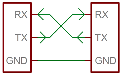
The communication is happening through the Serial bus, which consists of two wires - transmitting data (TX) and one for receiving data (RX).
Here detailed explanation from SparkFun: https://learn.sparkfun.com/tutorials/serial-communication/all
Wiring
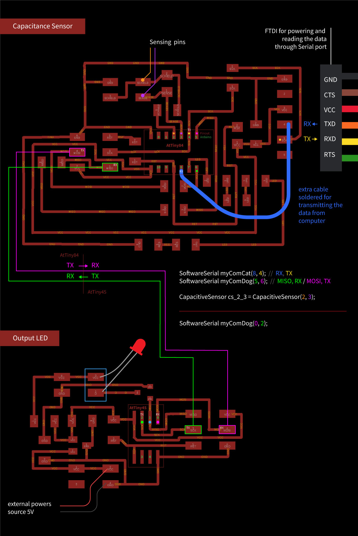
Underneath photos and schematics of the proper wiring.
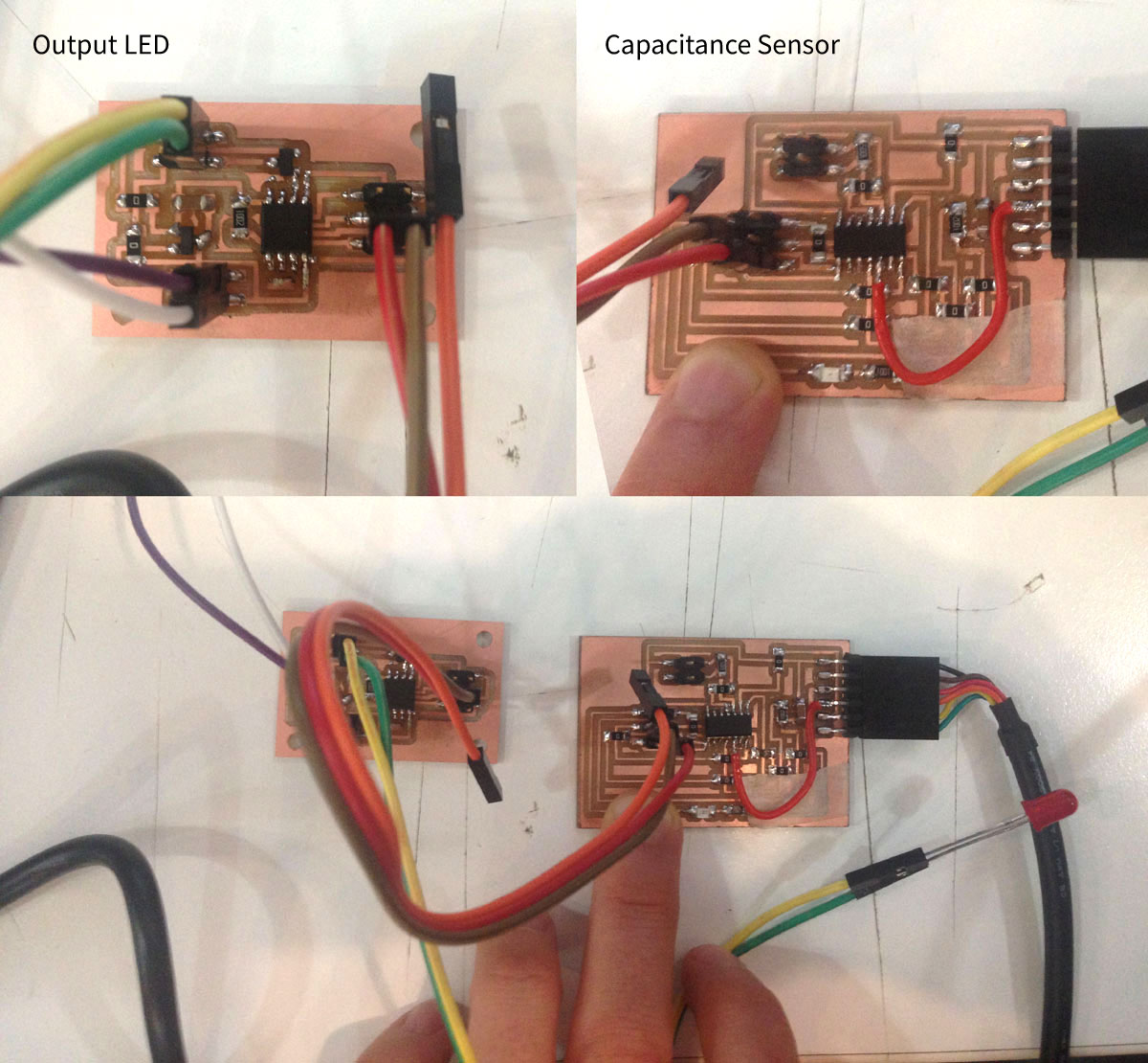
All the concept is about:
Sending the input data from Capacitance Sensor board through Serial Port to Output LED board. In other words getting the LED blink whenever somebody touchs the sensing pins. I’m communicating my two boards through two 6-pin ISP headers.
Code
I’m writting an Arduino code for each of two boards.
Important is to set up the proper pin numbers for the SoftwareSerial variable, include the proper libraries
Arduino code for CapacitanceSensor:
Including the library for serial communication and for capacitance sensor:
#include <SoftwareSerial.h>
#include <CapacitiveSensor.h>
Defining the proper pin numbers for the SoftwareSerial variable. Variable myComCat is responsible for printing the sensing values in the Serial Monitor, so I will get to know the range and setup the treshold (from which value the LED should light up). Variable myComDog will be communication channel between my two boards.
SoftwareSerial myComCat(8, 4); // RX, TX
SoftwareSerial myComDog(5, 6); // MISO, RX / MOSI, TX
Here I’m defining pins of 2x2 ISP header which will be sensing the touch:
CapacitiveSensor cs_2_3 = CapacitiveSensor(2, 3);
Setting the speed of data transfer:
void setup() {

  myComCat.begin(9600);
  myComDog.begin(9600);

}
Here I’m saying that value total1 comes from sensing the touch by previousely defined pins. Value should be printed in Serial Monitor.
void loop() {

    delay(10);

    long total1 = cs_2_3.capacitiveSensor(30);
    myComCat.println(total1);
And now whenewer the value is biggerthan 1000, myComCat and myComDog should write “1” in Serial Monitor:
if (total1 > 1000) {
      myComCat.write('1');
      myComDog.write('1');
  }
Anything else should write “2”
else{
      myComCat.write('2');
      myComDog.write('2');
    }
}
Arduino code for Output board
Including library:
#include <SoftwareSerial.h>
Defining Output pin and Software Serial variable (just for listening “1” or “2”. I don’t have to listen to the total1 values). The baud rate has to be the same as in code on Capacitance Sensor:
#define ledPin 1

SoftwareSerial myComDog(0, 2); // 5, MOSI, RX / 6, MISO, TX

char val;

void setup() {

pinMode(ledPin, OUTPUT);

digitalWrite(ledPin, HIGH);
delay(500);
digitalWrite(ledPin, LOW);

myComDog.begin(9600);

}
Now defining the behavior of LED: if the communication channel myComDog is available, and value is “1” than blink:
void loop() {
   if (myComDog.available())
   {
     val = myComDog.read();

   if (val == '1')
   {
     digitalWrite(ledPin, HIGH);

   }
If it’s “2” don’t blink:
 if (val == '2'){

     digitalWrite(ledPin, LOW);
   }
   delay(10);
   }
}
Now grabbing the programmer and uploading the code to the boards!
After hundreds of mistakes with wrong wiring and using the wrong pins its finally working. You can see the led blinking and the values in serial monitor are changing!
Coding for three boards
Since I’ve got back to this assignment while working on my Final Project I’m going to use this opportunity and involvethe vibration motor as an output. As a third board I’m going to use my Button-board from the Electronicd Design assignment as third node.
Since I’m going to send an adressed message to two different boards it’s important to set upthe proper timing method forboth of the boards. I’m going to use the millis function.
Here two references,goodforbeginners:
- https://www.norwegiancreations.com/2017/09/arduino-tutorial-using-millis-instead-of-delay/
- https://forum.arduino.cc/index.php?topic=503368.0
I’m going to send a number 1 or 2 through the Serial Port. I will connect my laptop to the Capacitance Sensor board which will play the roleof master board. Output board will be searching for 1 and answering only than. The same will do Button board, just will be answering only for number 2.
Code for the Capacitance Sensor
Capacitance Sensor will be connected to my computer, and will play a role of the master board. The code that I will upload is already written for the sensor function which is important for my final project.
#include <SoftwareSerial.h>
#include <CapacitiveSensor.h>

#define NUM_SAMPLES 30
#define THRESHOLD 5000

SoftwareSerial myComCat(8, 4); // RX, TX
SoftwareSerial myComDog(5, 6); // 5MISO, RX / 6MOSI, TX

CapacitiveSensor cs_2_3 = CapacitiveSensor(2, 3);

// Change this depending on the values coming
// fromthe sensor.
unsigned long average = 0;
unsigned long threshold = THRESHOLD;
unsigned long samples[NUM_SAMPLES];
int currSample = 0;
int maxSamples = NUM_SAMPLES;

void setup() {
  myComCat.begin(9600);
  myComDog.begin(9600);
}

void loop(){
  myComCat.listen();
  while (myComCat.available() > 0) {
    char inByte = myComCat.read();
    myComDog.write(inByte);
  }

  delay(100);

  unsigned long reading = cs_2_3.capacitiveSensor(30);

  if(currSample < maxSamples){
    // in the beginning we have to read the first NUM_SAMPLES samples
    // since the array is empty.
    samples[currSample] = reading;
    currSample++;

    myComCat.println("sampling...");
  }else{
    // when we are donre reading inthe NUM_SAMPLES readings
    // we have an array we can use for averaging
    // and we have to shift all readings of an array
    // we have to drop the first one and add one on top
    // so that we still have only NUM_SAMPLES readings

    // remove one sample from the beginning
    // and add one sample at the end of the array
    for(int i = 0; i < maxSamples; i++){
      if(i < maxSamples - 1){
        samples[i] = samples[i+1];
      }else{
        samples[i] = reading;
      }
    }

    unsigned long sum = 0;
    for(int i = 0; i < maxSamples; i++){
      sum += samples[i];
    }

    unsigned long numSamples = NUM_SAMPLES;
    average = sum / numSamples;
    myComCat.print("sum: ");
    myComCat.print(sum);
    myComCat.print("\t");
    myComCat.print("average: ");
    myComCat.print(average);
    myComCat.print("\t");
    myComCat.print("reading: ");
    myComCat.println(reading);

    if (reading > average + threshold) {
      myComCat.println("Fingers move!");
      myComDog.write('1');
    }
  }
}
Code for the Output Board
#include <SoftwareSerial.h>

const int vibPin =  1;
unsigned long previousMillis = 0;
unsigned long interval = 2000;
Since we use the port for listening only (on RX, which is 0) It is ok, that the TX pin is the same as vibPin.
SoftwareSerial inputPort(0, 1);

void setup() {
  pinMode(vibPin, OUTPUT);
  inputPort.begin(9600);
  previousMillis = millis();
}

void loop() {
Move the DC Motor
  unsigned long currentMillis = millis();
  unsigned long timePassed = currentMillis - previousMillis;
  if (timePassed > interval) {
    digitalWrite(vibPin, LOW);
  }else{
    digitalWrite(vibPin, HIGH);
  }

  while (inputPort.available() > 0) {
    char inByte = inputPort.read();
The address of this board is 1. Whenever we receive 1, we light turn on the motor.
    if (inByte == '1') {
      previousMillis = currentMillis;
    }
  }
}
Code for the Button Board
#include <SoftwareSerial.h>

const int ledPin = 7;
unsigned long previousMillis = 0;
unsigned long interval = 2000;

SoftwareSerial inputPort(6, 5);

void setup() {
  pinMode(ledPin, OUTPUT);
  inputPort.begin(9600);
  previousMillis = millis();
}

void loop() {
Turn the LED on for N seconds
  unsigned long currentMillis = millis();
  unsigned long timePassed = currentMillis - previousMillis;
  if (timePassed > interval) {
    digitalWrite(ledPin, LOW);
  }else{
    digitalWrite(ledPin, HIGH);
  }

  if (inputPort.available()) {
    char inByte = inputPort.read();
The address of this board is 2. Whenever we receive 2, we light up the LED
    if (inByte == '2') {
      previousMillis = currentMillis;
    }
  }
}
Serial Communication between Capacitance sensor and Raspberry Pi
To work with Raspberry Pi I have to download the Raspbian system (the version with the desktop) burn it on the mini-sd card (need 5 MG).
To burn a disk image on the card one has to use e.g Etcher. I can open .zip file directly and burn it on mini-SD card. One have to put it into pocket for SD card to plug it into your computer.

Once I have a disk image on the mini-SD burnt, I will set up my Raspberry Pi. I’m connecting all the components that I need which are:
- keyboard
- mouse
- HDMI cable (through HDMI adapter) connected to the screen or projector
- Raspberry pi charger (IMPORTANT: at the end)
- FTDI cable for reading the data
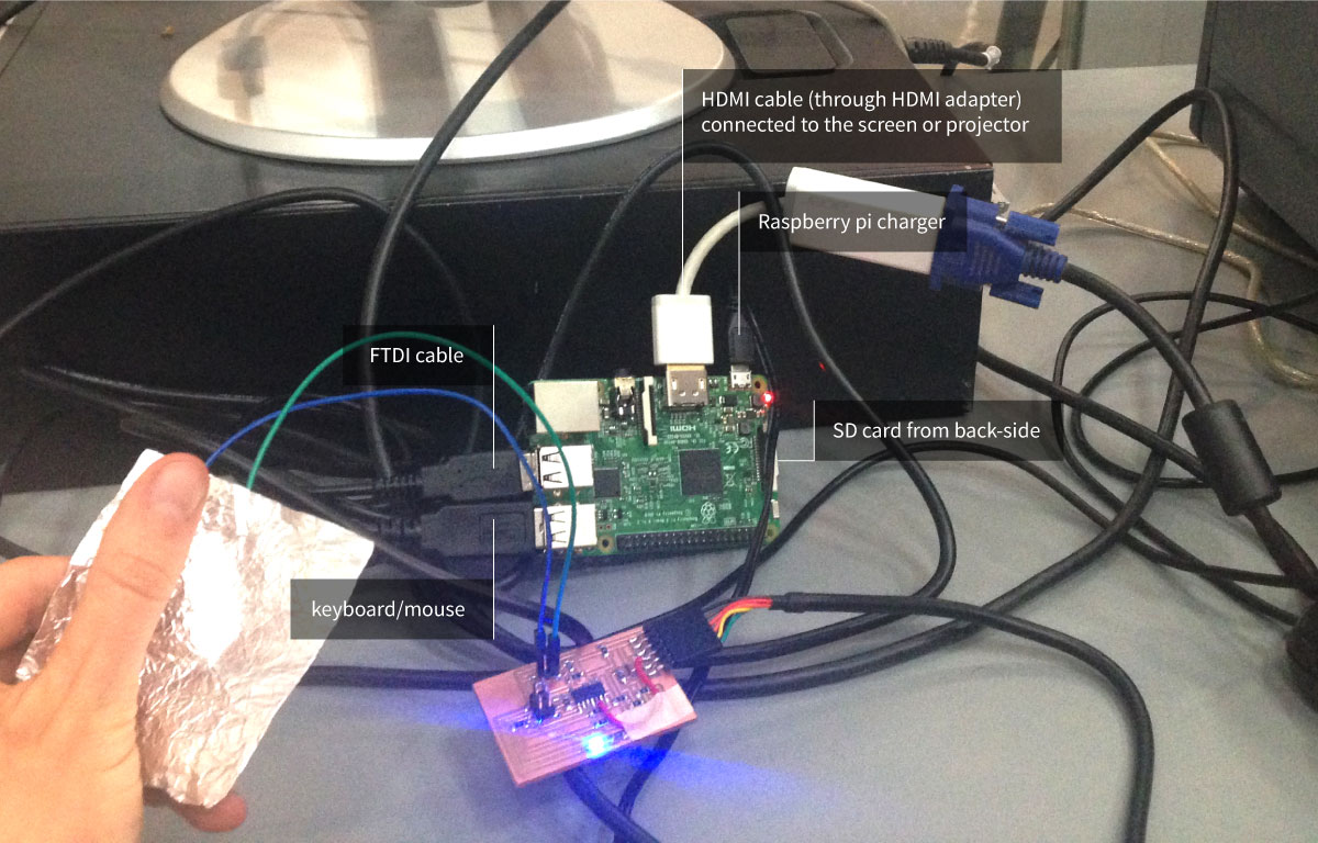
I’m booting up and seems that everything is working! What I’m going to do now is to test if my previously written sketches for interface (Arduino part and Processing part) connected with capacitance sensor, are going to work on Raspberry Pi as well.
I copied sketches from my laptop into usb and copied it on the RasPI desktop. Now I have to modify the Processing sketch by changing the serial port.
Commuication with Raspberry Pi goes through terminal. I’ve learned some useful commands:
- listing the ports:
ls/dev/tty* - installing Processing directly from terminal:
curl https://processing.org/download/install-arm.sh | sudo sh - rebooting:
sudo shutdown -r now
I’ve asked for advice and got to know that the serial port of RasPI is: ttyUSB0. I’ve modified my sketch, connect the capacitance sensor board to the PI and run the Processing sketch. Worked out!
The deal is: whenever I’m touching capacitance sensor on the screen the white circle got displayed (size according to the value being send by Arduino code from my board to serial port of RaspberryPi). And than whenever I’m clicking with mouse inside this white circle, the small LED on my board lights up.
Useful links:
Raspberry Pi pinout: https://pinout.xyz/
Running Processing on Raspbian: https://github.com/processing/processing/wiki/Raspberry-Pi#serial
Files made during this assignment:
2-boards communication:
Arduino code Sensor
Arduino code Output
3-boards communication: