Week 7: Embedded Programing
This assignment is very difficult for me, i never programming, i never programming Arduino in my life. I always admired Arduino and its potential. When now Antonio Go! I have to program an ATtiny44A microcontroller on my Hello Button + LED. I am using the Arduino software (version 1.0.3). The first step download the Arduino software from the Arduino site and istall the drive (link)
I followed the tutorials to download and install the Arduino software, ATtiny support (driver) and the FTDI driver. I took power from my laptop to the LED and BUTTON ('Hello Echo') board (made in previous week) and connected the FAB ISP to act as a programmer.
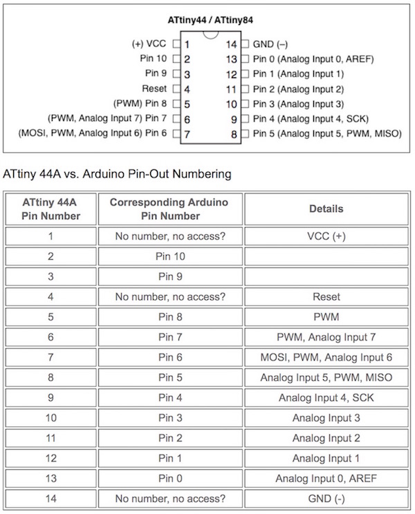
Note that the pinouts on the microcontroller are not the same numbers in the Arduino code.
Check the corressponding numbers in the diagram and chart below:
After i installed the bord file ATtiny44A on Arduino
When I first went to launch the IDE, the ATtiny would not show up in the Arduino Tools/Board list. The file structure, following an automatic unzip, kept a folder called "attiny-ide-1.6.x" in the pathway, which prohibited the board showing up as a choice. So, on the Mac, at least this needs to be removed so that you end up with the following folder structure : Documents > Arduino > hardware > attiny > avr
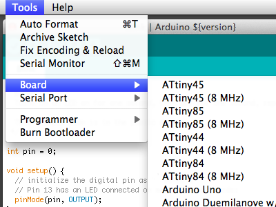
After by launching the Arduino IDE software again, and through 'tools' in the top menu, I was able to select the specifics for my set up: board, clock, processor, port and programmer.
Next step is run the "Burn Bootloader" command from the Tools menu. This configures the fuse bits of the microcontroller. This step is only required once for each microcontroller.
I spent some time trying to follow, understand and make very simple but successful modifications to the existing examples in the Arduino IDE, such as 'Blink'. This was my first entry into coding and slowly, I began to see how programmers build and develop programmes.
I decided that I would try to write a very simple code to simulate this simple series of events.
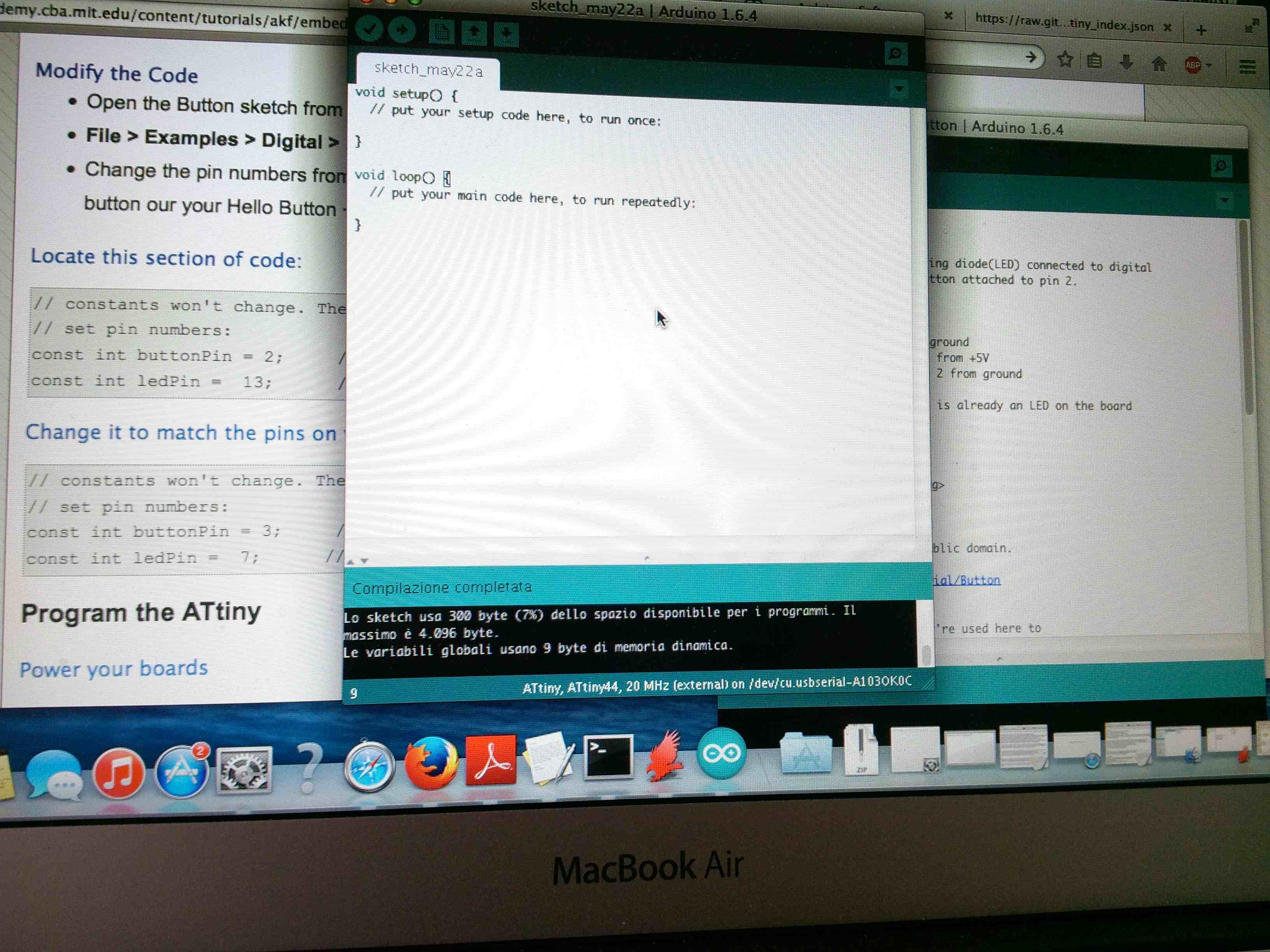
So I charged the Button example program of Arduino IDE making slight modifications of the pins in the code. Thanks to this tutorial did very well I found the comparison tables to find the pin on my microprocessor, number 13. (link)
Turns on and off a light emitting diode(LED) connected to digital
pin 13, when pressing a pushbutton attached to pin 2.
The circuit:
* LED attached from pin 13 to ground
* pushbutton attached to pin 2 from +5V
* 10K resistor attached to pin 2 from ground
This is the link code.
arduino file
http://www.arduino.cc/en/Tutorial/Button
*/
// constants won't change. They're used here to
// set pin numbers:
const int buttonPin = 2; // the number of the pushbutton pin
const int ledPin = 13; // the number of the LED pin
// variables will change:
int buttonState = 0; // variable for reading the pushbutton status
void setup() {
// initialize the LED pin as an output:
pinMode(ledPin, OUTPUT);
// initialize the pushbutton pin as an input:
pinMode(buttonPin, INPUT);
}
void loop(){
// read the state of the pushbutton value:
buttonState = digitalRead(buttonPin);
// check if the pushbutton is pressed.
// if it is, the buttonState is HIGH:
if (buttonState == HIGH) {
// turn LED on:
digitalWrite(ledPin, HIGH);
}
else {
// turn LED off:
digitalWrite(ledPin, LOW);
}
}
The video with my result, Hello Heco Led turn on :)
This week helped me to understand many things that I will apply in the construction of the FABDUINO for my final project.
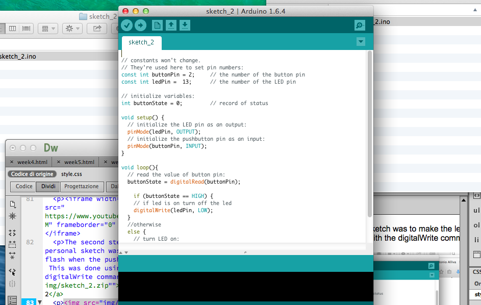
The second step is to do my personal sketch was to make the led flash when the push button was pressed. This was done using a delay with the digitalWrite command. arduino file scketch 2