Week 10: Input Device
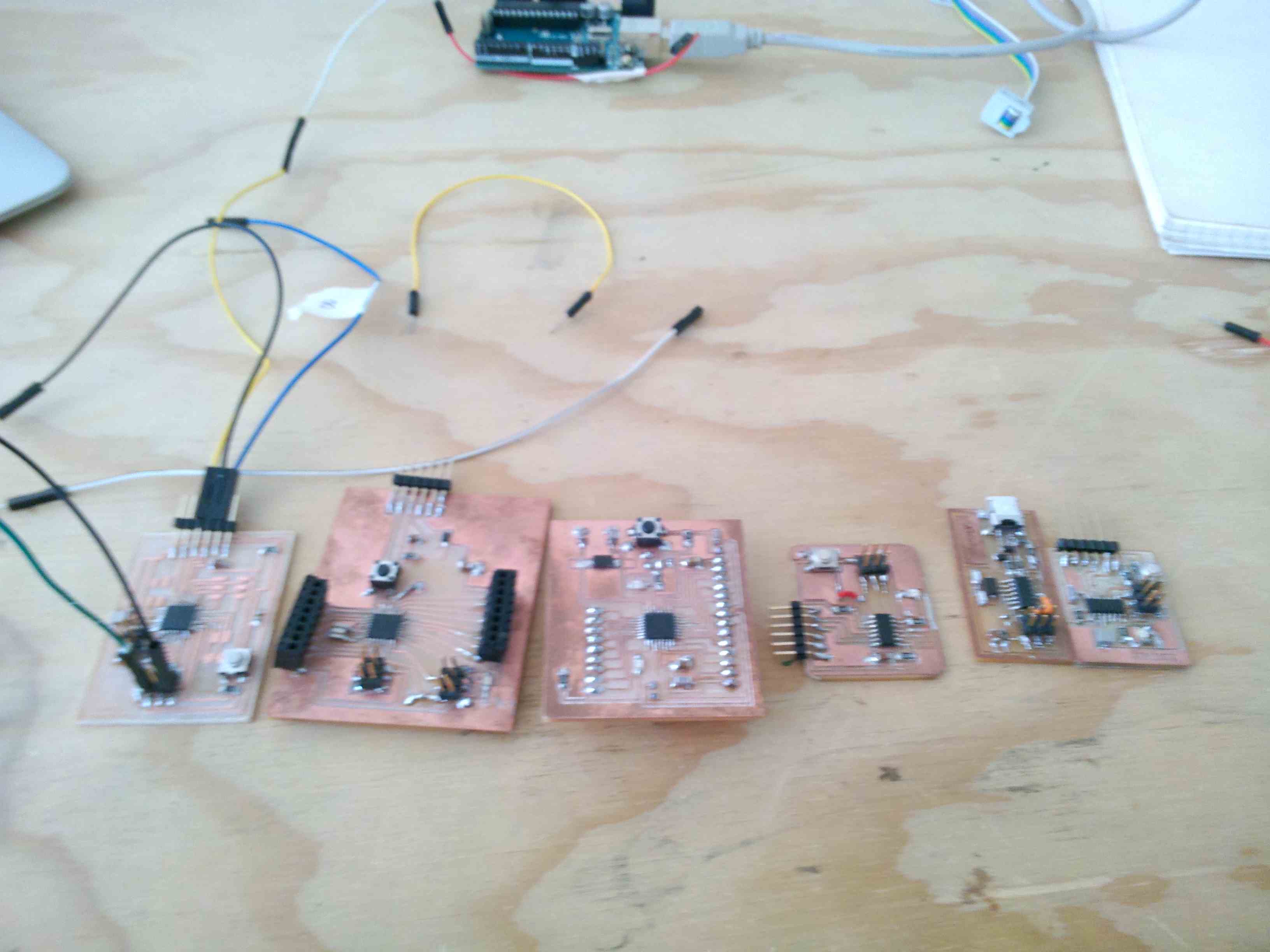
For input devices I realized my Fabduino that will be inserted in the base of the lamp of my final project. An input signal, with an IR MOTION SENSOR that will turn on the LED lamp. I started trying to create my Fabduino customized by designing the tracks and position of components. I made two versions, which I have operated (The first version ran for a short time). Perhaps a little too daring, too many pins because I did not need. We think it is the proximity to the slopes which was to short circuit but also especially the processor that sometimes seemed unwilling to work. After a series of consultations both of the web, but most of my colleagues of the course, i realized an Fabduino much smaller size, fewer components and pin. (Fabduino file test one)
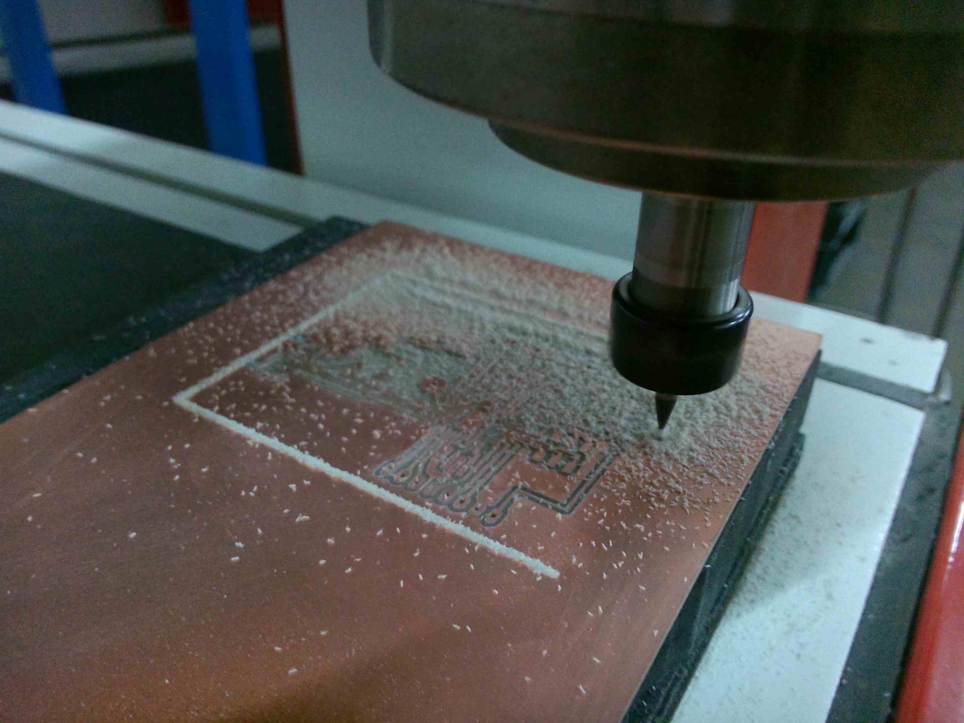
I just wanted to tell you that my path before arriving to a Fabduino was difficult. The photos below show this. I used Eagle for the design, illustrator for export in DXF and Aspire for milling.
I thought it was important for me to finish the project and work on something practical i found the tutorial in this assignment, i will manufacture a Fabduino board, following the tutorial Hello Fabduino. After i use Aspire and prepare gcode for the milling machine, check the tracks, because i'm going to mill with a 0.4mm endmill and I'm to check if the distance between eack track is correct. So I set Aspire to simulate the mill operation with the rigth mill tool. Next step cutting proceeded to mount the electronic components.
Here are the file with the fab modules (file).
After soldering all the components present in the tutorial link and doing the smoke test, to check the operation of my Fabduino i used some of the examples base Arduino, specifically the blink test to verify the operation of my Arduino. This is the video.
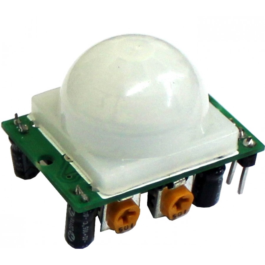
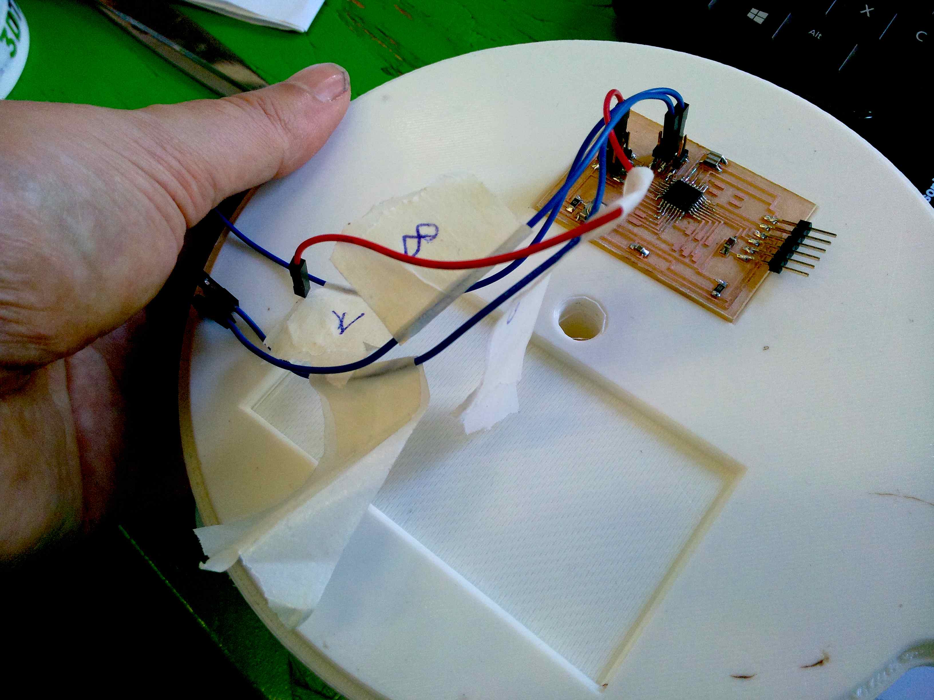
Next step is downloaded the program through the programmer input and output for my lamp, by connecting the two pins on the number pin 7 connect IR Motion Sensor model
and in the pin 8 the Relay module.
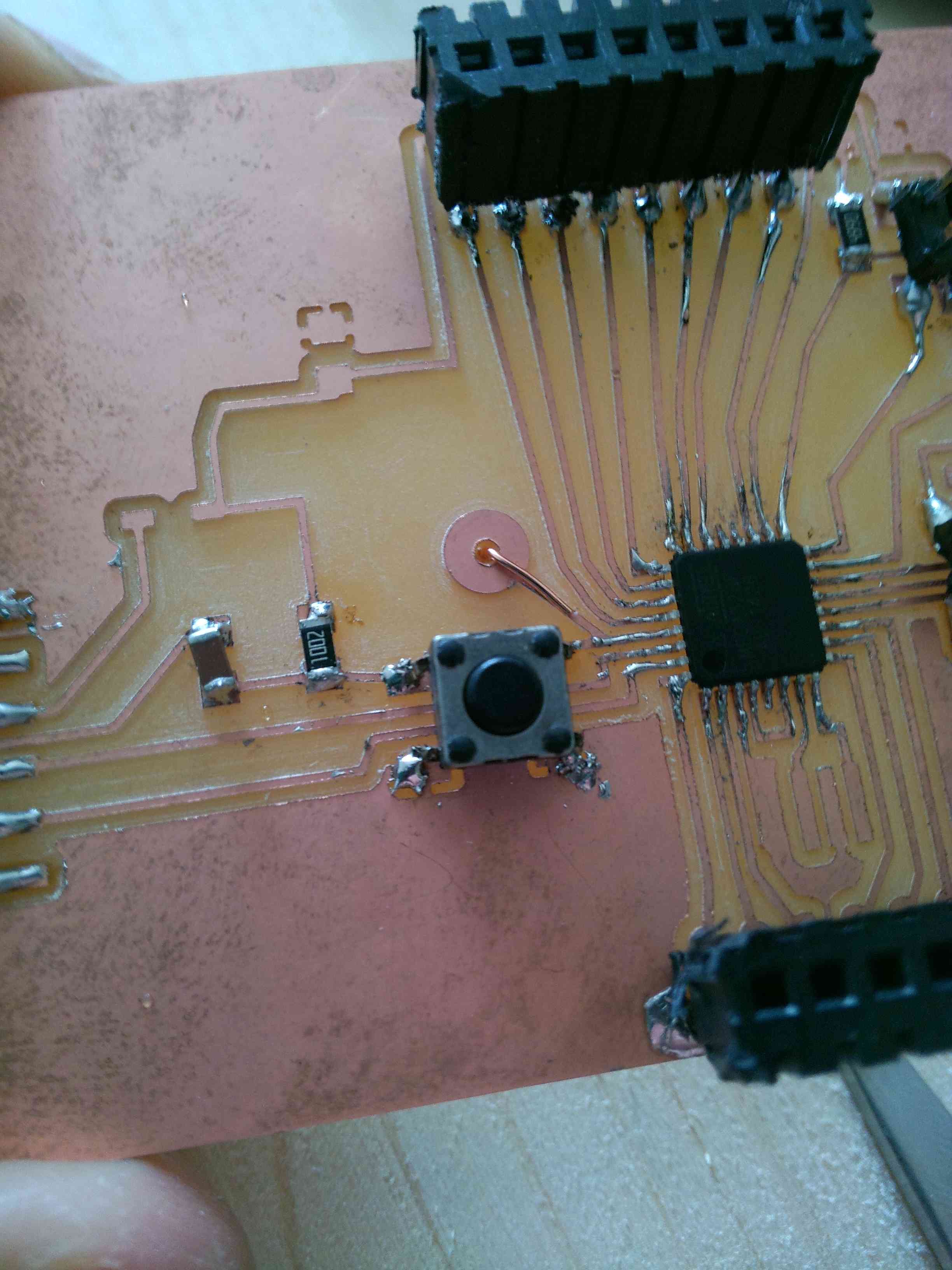
I have used in the input device assigment my Fabduino board. This is my board milled for the final project. I have design my board, milled and join. Here are the file.
This is the commented code:
int irmotionPin = 7; // Pin of IR Motion Sensor
int relayPin = 8; // Pin of Relay Module
void setup(){
Serial.begin(9600);
pinMode(relayPin, OUTPUT); // Set Pin connected to Relay is an OUTPUT
pinMode(irmotionPin, INPUT); // Set Pin connected to sensor is an INPUT
digitalWrite(relayPin, LOW); // Set Pin to LOW to turn Relay OFF
}
void loop(){
if (digitalRead(irmotionPin) == HIGH) { // If Motion detected
Serial.println("motion on");
if(digitalRead(relayPin) == LOW){
digitalWrite(relayPin, HIGH); // Turn Relay OFF
Serial.println("Relay is OFF");
delay(5000);
}
else{
digitalWrite(relayPin, LOW); // Turn Relay OFF
Serial.println("Relay is ON");
delay(5000);
}
}
else{
Serial.println("motion off");
}
}
Below is a video that shows the operation and put program on my Fabduino. It was a really exciting time for me :)
After loading the program i started doing test to find that the sensor recognized the movements and made it through the use of the command "Serial Monitor" which has been very useful.
The sensor with the card needs five second to be working, and besides that I had to adjust manuamente the screws to the right sensibility sensor. The cost of the sensor was eur 7.00
Before using my Fabduino it used a real Arduino Uno, to see if the code was right and everything worked out for the best. This is to avoid that could ruin the product from me :)
To see the end of the work you have to go to the assignment 12. (Arduino file)