Week 11: Output Device
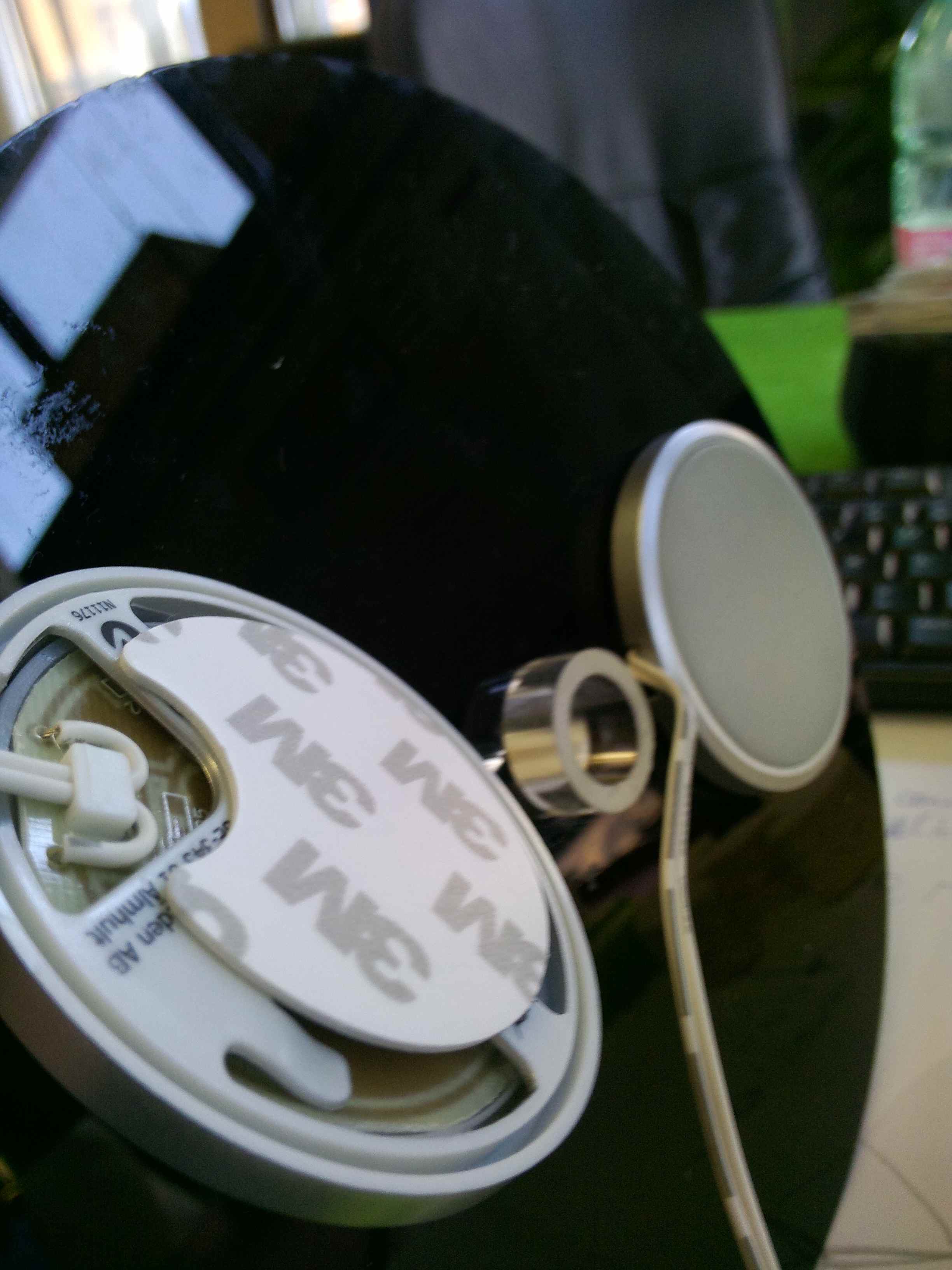
For complete the assignment "output device" i continued the realization of the lamp of my Hubdesk with Fabduino form. After using the sensor input now my job is to connect the signal inputs one output with the function of the LEDs turn on my lamp. The tools i used were a relay and n. 2 Ikea DIODER LED model I found in the trash Fablab. This is the Arduino code:
int irmotionPin = 7; // Pin of IR Motion Sensor
int relayPin = 8; // Pin of Relay Module
void setup(){
Serial.begin(9600);
pinMode(relayPin, OUTPUT); // Set Pin connected to Relay is an OUTPUT
pinMode(irmotionPin, INPUT); // Set Pin connected to sensor is an INPUT
digitalWrite(relayPin, LOW); // Set Pin to LOW to turn Relay OFF
}
void loop(){
if (digitalRead(irmotionPin) == HIGH) { // If Motion detected
Serial.println("motion on");
if(digitalRead(relayPin) == LOW){
digitalWrite(relayPin, HIGH); // Turn Relay OFF
Serial.println("Relay is OFF");
delay(5000);
}
else{
digitalWrite(relayPin, LOW); // Turn Relay OFF
Serial.println("Relay is ON");
delay(5000);
}
}
else{
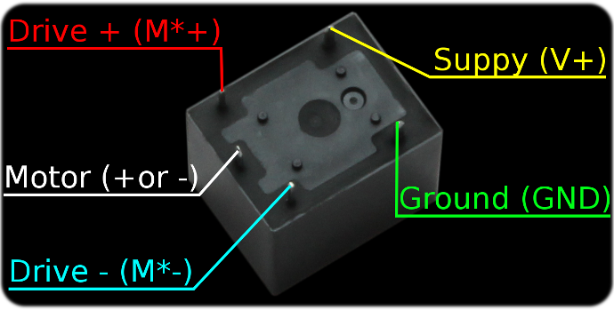
It was very difficult to understand what were the five pins that the Relay. With the help of Alessandro and Sergio and our tester we have identified the exact locations where to place the GND and VCC. What were the switches on and off.
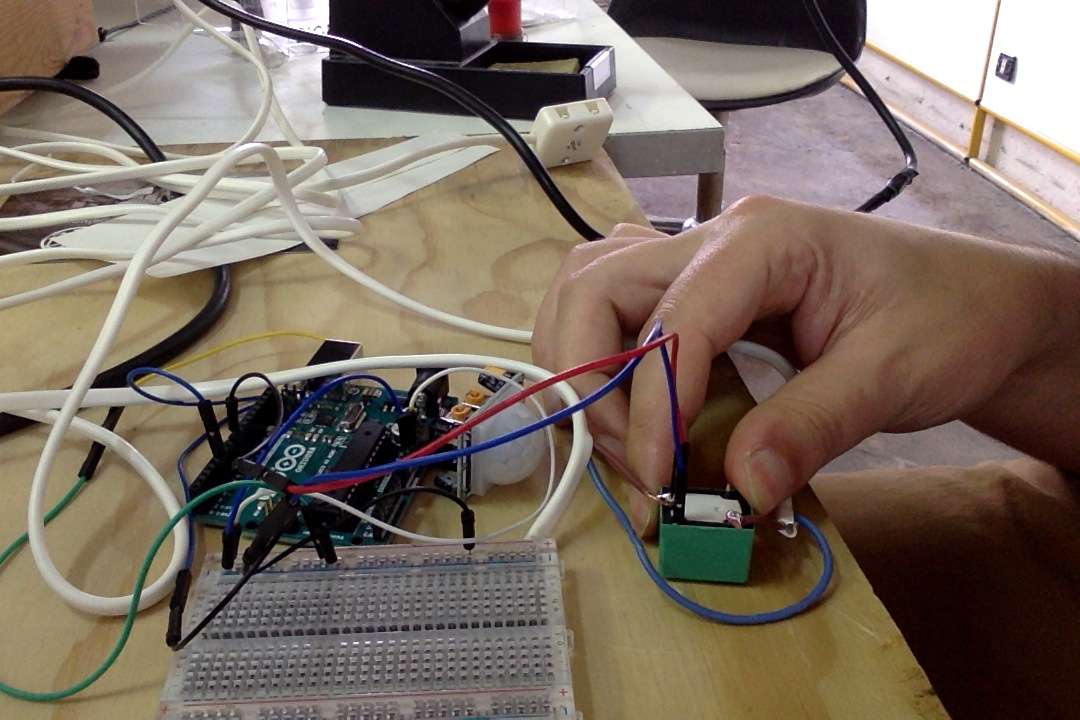
After connecting all the pins, one related to the output signal is the number 8, I made many tests but the LEDs were lit only when they wanted them, I was very sad for two days.
Thanks to the serial monitor that showed me the functions of the sensor and after realizing that he needed to react to the sensor at least 5 second pause, I had my first successes. Finally I adjusted manually screw sensor sensitivity according to my needs and everything worked perfectly. (Arduino file)
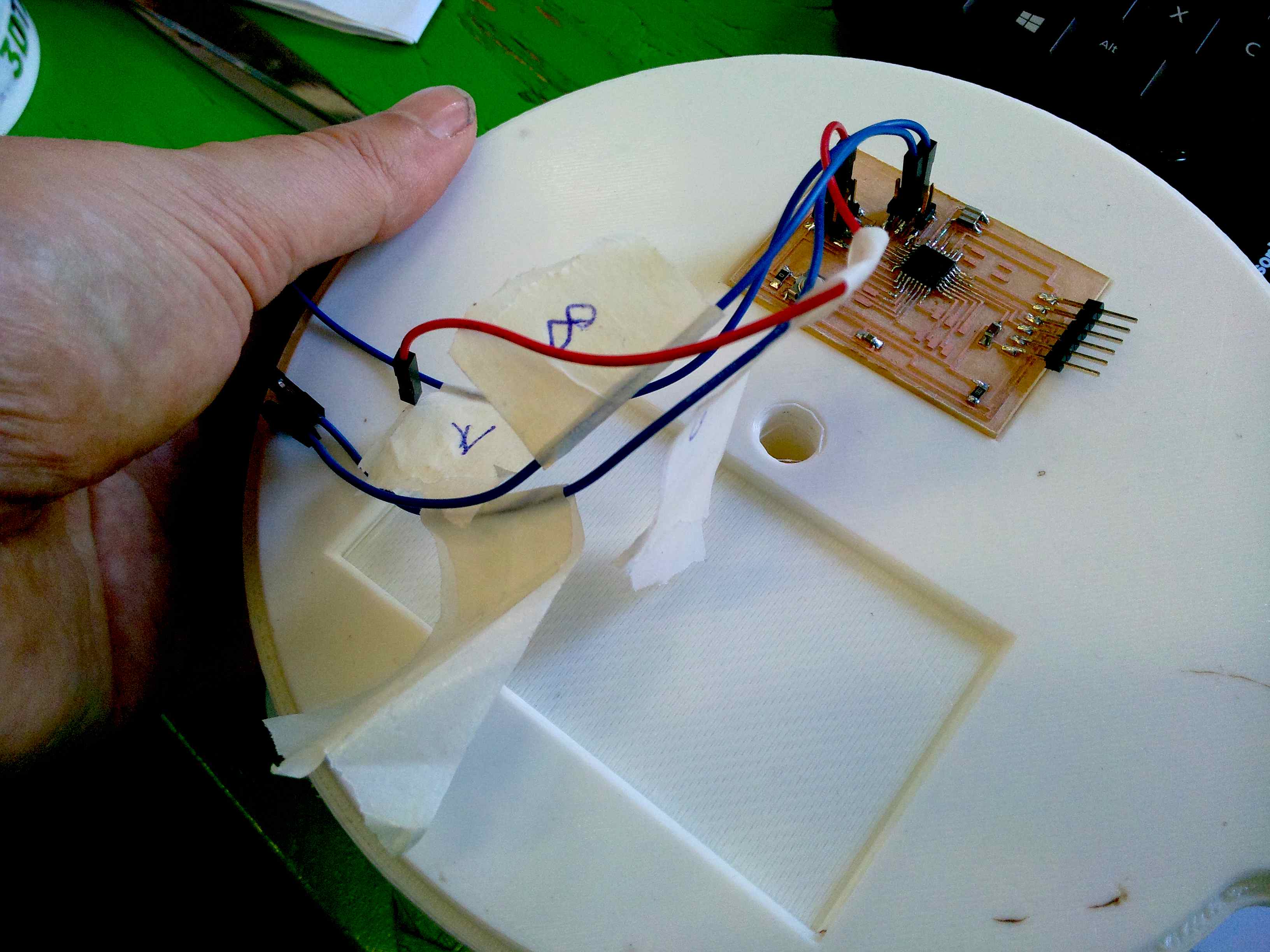
For this assignment i use my board Fabduino, design and milled for the final project that I have used in the input assignment.
I have design my board, milled and join. Here are the file.