Week 6: Eletronics Design
Step 1: I download the software Eagle, the last realis of eagle-mac-7.2.0.zip. and import component libraries, and installed the package Fab.ibr. Later we tried the components to be included in the initial three resistances, led, ground, capacitor. I studied what use components and how it should operate a scheme elettronic, because for me it was the first time. This is PNG sample
schema
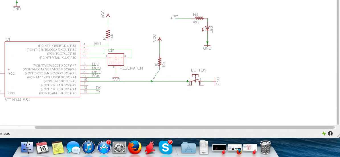
Eagle allows you to view the board in different ways, the first allows you to see where and how they are distributed and connected components, while the other option allows you to see the actual design of the board .
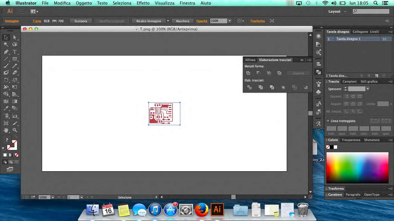
I transform the image to a vector and export as DXF, and i pull the file in but when I try to see in Aspire.
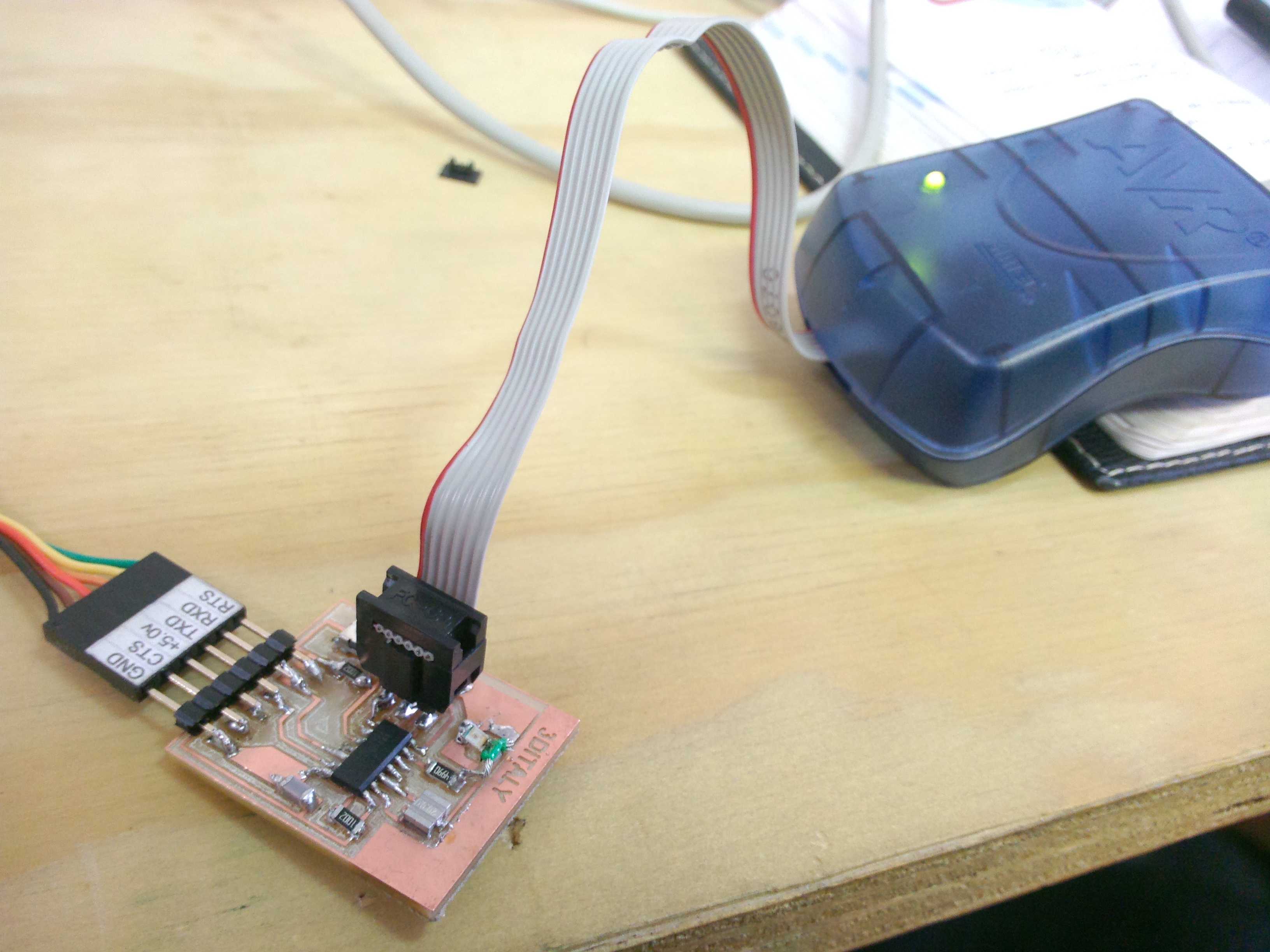
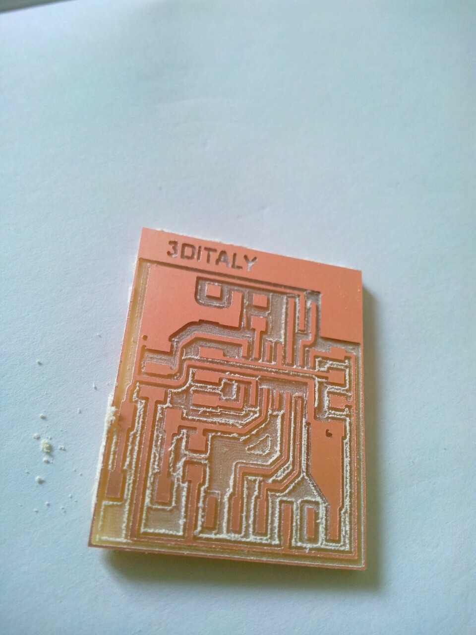
Step 2: Milling board and soldering components. Working area is 1800mm x 2200mm (40 min).
Hello_Echo list:
1. R1 10k / Res 10.0k ohm 1206 SMD
2. R2 10k / Res 10.0k ohm 1206 SMD
3. R3 499k / Res 499k Ohm 1206 SMD
4. C1 1uf / CAP CER 1UF 1206
5. Crystal 20 Mhz / CER Resonator 20.00 Mhz SMD
6. IC1 t44 / ATTINY44A; IC MCU AVR 4k FLASH 20Mhz 14SOIC
7. J1 ISP / 2x3 connectors
8. J2 FTDI / 6 connectors
9. LED red or green clear 1206 SMD
10. Switch Tactile
Step 3: Once you have found the components Welding
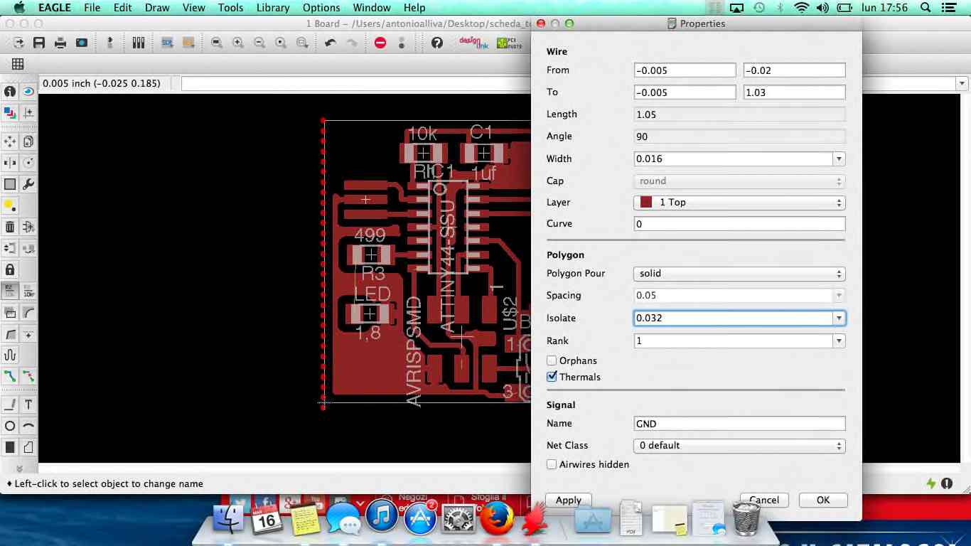
I have made two Eagle, the first after checking with the programmer I worked.
I think it was too small in size and the slopes were too close, so I expanded the size of the tracks and created more distance between them. This latest work!
File eagle, png, bmp, svg. (link)