>>>>FINAL PROJECT<<<<
Final Project Time. The Plan:
Make the components:
- Felt artwork
- Large LED array
- Microphone board
- Arduino (not part of initial concept)
- Frame (not part of initial concept)
Integrate the components
- Get the sound from the microphone board to use as input to the LED array
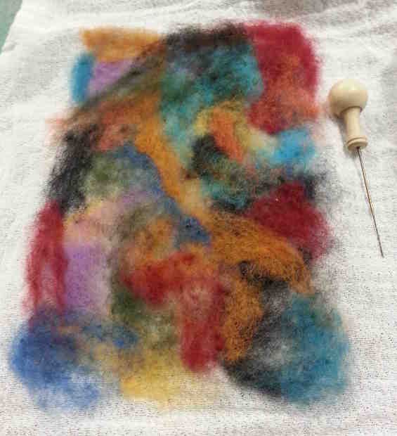
Felt Artwork
The first thing that I did was make my piece of needle-felted artwork. Digitally fabricated. With my digits.
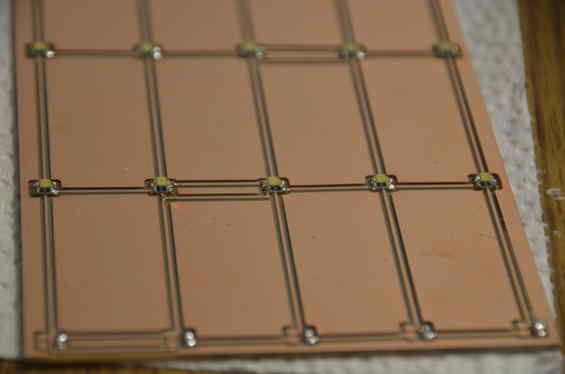
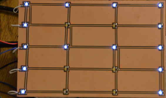
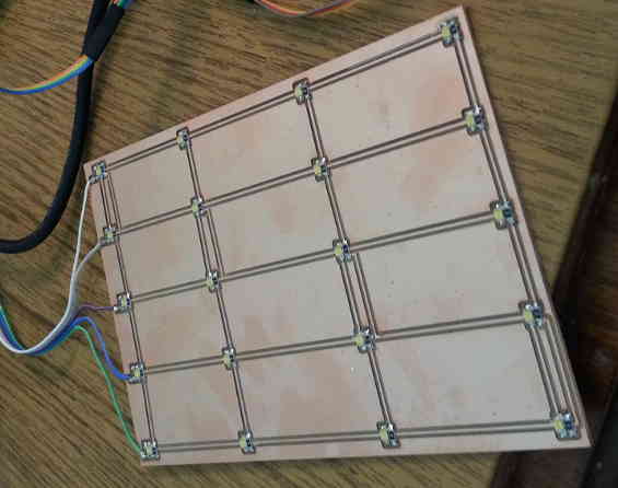
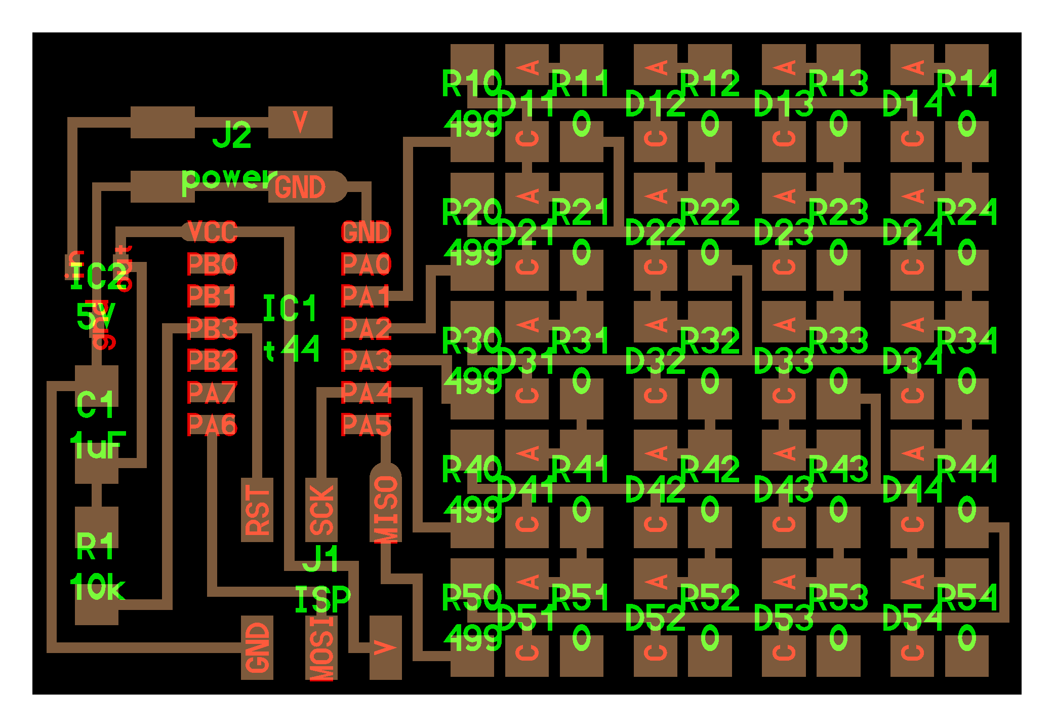
Large LED Array
I took the hello world LED array that I made in week 13 and set out to make it 6" wide by 4" high and double-sided. I wanted all of the LEDs on the side that would go behind the fabric and the rest of the electronics on the back. I started by first doing this in Eagle but ran in to two problems:
- My Eagle skills are deficient enough to make this very time consuming
- The free version of Eagle only allows you to make circuit boards of a certain size, which was not large enough to adequately go behind the artwork.
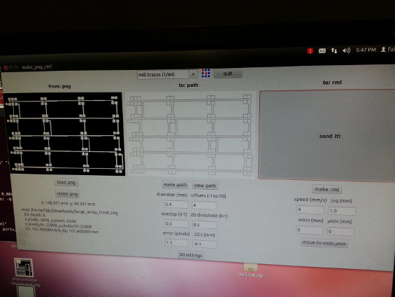
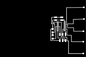
I then set out to edit the cut files using the GIMP. I took the original png for the traces and opened it. I then created a new file with a canvas size of 6" x 4" and copied and pasted the components where I needed them.
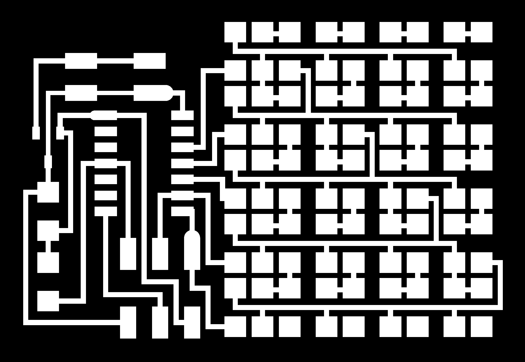
Screenshot of the fab module for the LED side:
As the board was milling, things seemed a little off:
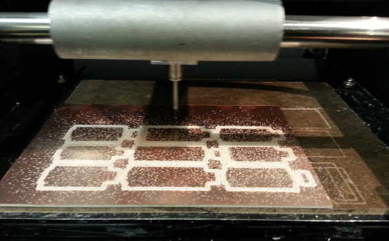
GIANT TRACES!!! Unless I was going to switch everything to a 2512 smd package size, this board just was not going to work....
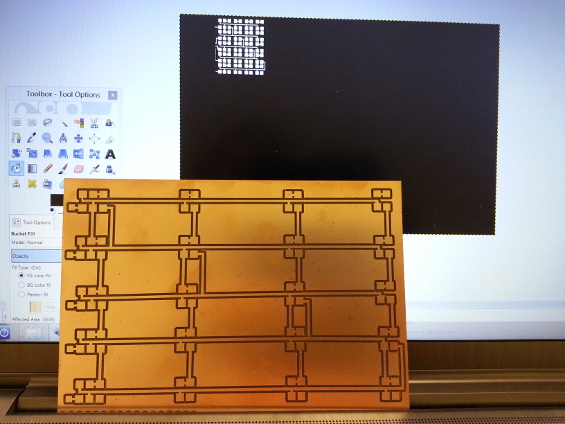
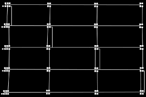
As I said before, I set the canvas size, then copied and pasted the traces from the original picture. After discussing this with Anna, she suggested that I take the original picture of the traces and increase the canvas size on that image. I tried that and it ended up working. Here is a comparison of the images:
Fail: (setting the canvas size first on a blank image)
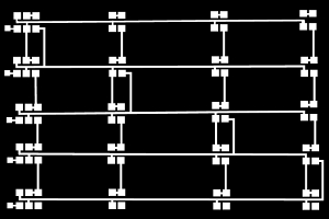
Success: (using the original image and increasing the canvas size to the correct dimensions)

Tools of a Champion
Since I live 1.5 hours away from the lab, I decided to go out and (finally) get my own soldering iron and related equipment. This allowed me to do all of the stuffing at home, which helped keep me on schedule.
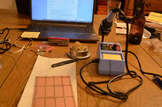
Stuffing at home:
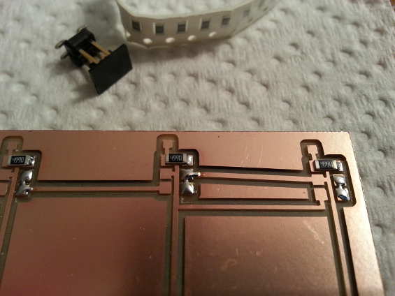
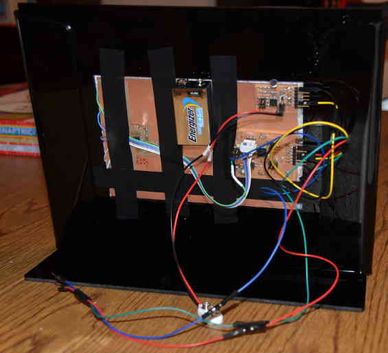
I used jumper wires to make the connections around the side of the board. The first thing that I did was flash it wish the code that I programmed the smaller LED array with in week 13, which was my name scrolling.
Once I realized that I was going to use the Arduino, I disconnected the jumper wires and attached longer wires in order to attach a 6-pin connector so I could neatly connect the board to the Arduino.
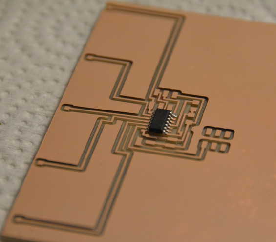
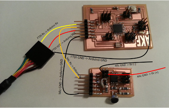
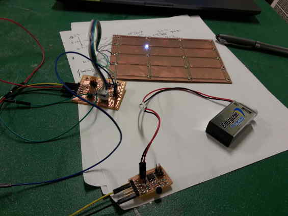
Getting Output from the Microphone Board
I used the microphone board that I made back in week 10. I had initially made the microphone board, but could not program the microcontroller. Once I realized that no one in class had gotten it to work, we knew something wasn't right. Kaimen traced the connections and found that the FTDI connector did not have VCC hooked up through that connector, but instead was set up to only be powered through the battery. A description of the fix can be found on Kaimen's page.
My original idea was to use the two hello world boards together, without using an arduino. Anna led me to a link to a former student in MAS863.10, Yeon Wha Hong, that looked promising. Unfortunately, I noticed that the code never worked for that student, and not being very fluent in C programming, I opted to use an Arduino that I made.
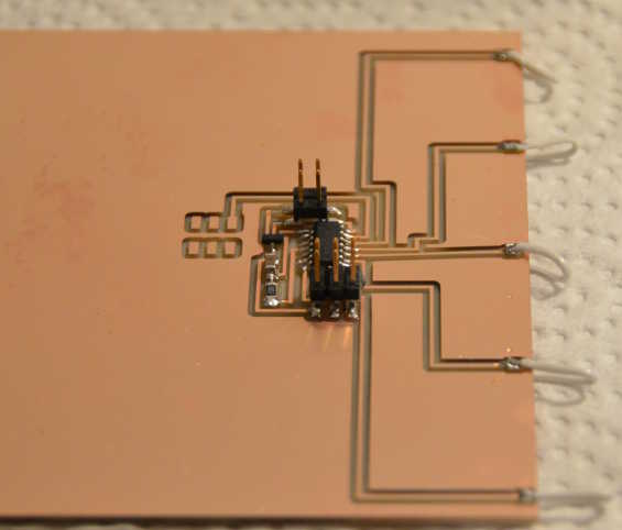
Here is how I connected everything up to this point.
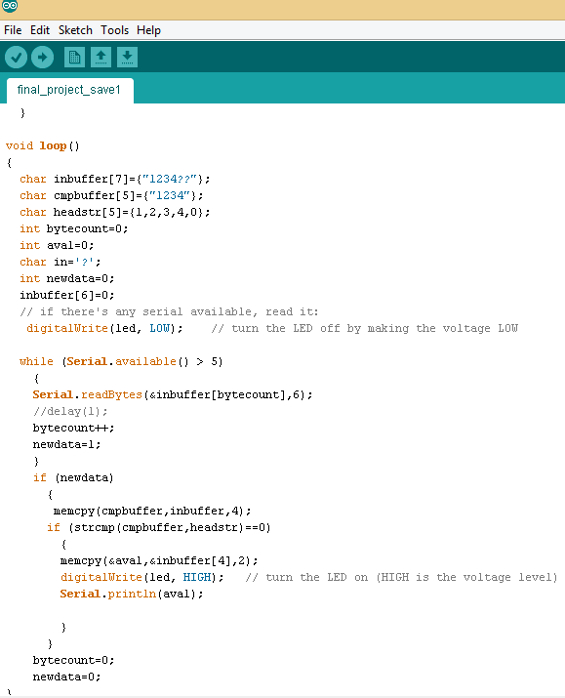
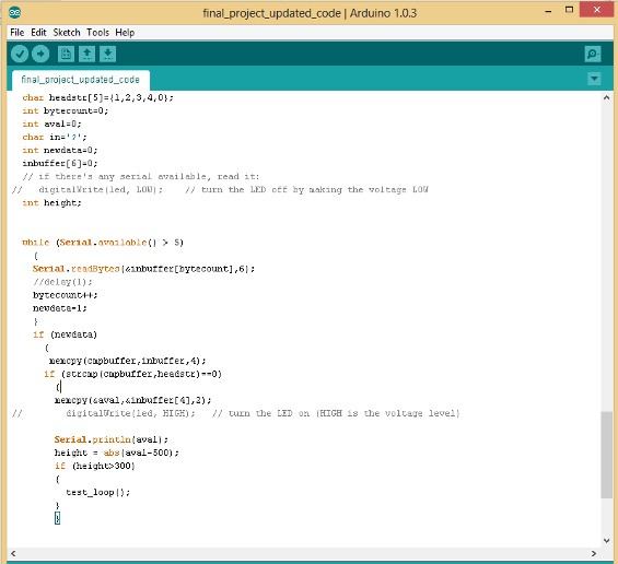
I first set out to understand the output of the microphone board. I consulted with a friend who is much more familiar with C than I am to trace through the original C code. I was able to write some Arduino code that printed the output of the microphone board.
This printed data in the serial monitor that showed that when the microphone was not receiving sound that the value hovered around 500. When the sound input was loud, it was either 0 or 1023 which is consistent with the output being a wave where the amplitude increases as the noise increases.
Connecting the LEDs to the Arduino
I found several webpages that had code for Chalieplexing LEDs in Arduino.
One particular website was at the Make Blog and was called Charlieplexing LEDs with an AVR ATmega328...that's right - perfect! This covered Charlieplexing 12 LEDs on 4 pins. I also found some code by riaancornelius for Charlieplexing 20 LEDs on 5 pins on Instructables.
This video is of the 12 LED code:
Putting Everything Together
Using this information, I combined the 2 codes (microphone input and LED output) and added a new definition of the height of the sound wave and said that if the absolute value of the wave height, minus the nominal value (which I put at 500), was greater than 300, then the LED cycle would run.
When I hooked it all up, it worked....sort of. It's almost as if it is not taking a reading frequently enough to respond on time, so I need to analyze the initial C code some more to try to understand it.
A little laying out:
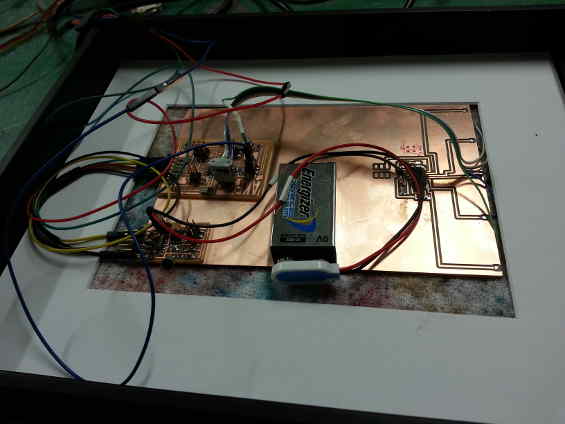
After much tinkering, this was what it should look like:
Final Order of Business - The Frame
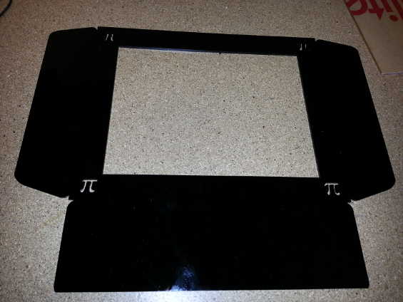
I received feedback that it would be frowned upon to use a purchased picture frame, so after giving it some thought, I whipped this guy up in Inkscape to make out of 1/8" acrylic on the laser cutter.
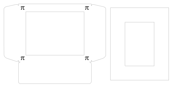
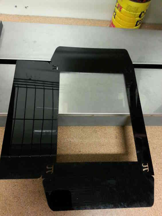
I used the acrylic bender (with the expert tutelage of Ted, one of our Teaching Assistants) to form the frame shape out of the piece on the left. The piece on the right above is a frame for the circuit board and will give support to the entire structure.
Here is the laser-cut frame:
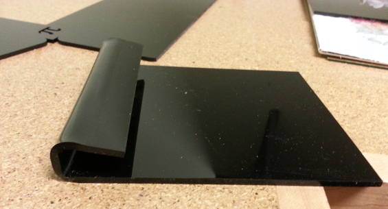
Here is a trial bend on a piece of scrap acrylic. Since the frame needed a double bend on the sides, the trial was necessary to make sure that there would be no tensile overload in those areas.
Around 1:30am, this was the final product in class:
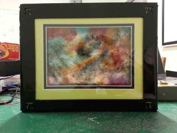
All put together:
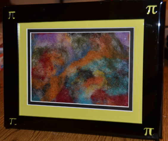
For now the circuit board is being held in place with electrical tape, but after some tweaking I will find a better way to secure everything
Video:
Next Steps and Conclusions
Next Steps:
- I am not satisfied with the response of the microphone, so I will need to do some more work on the code in order to get it working properly.
- After that is working to my satisfaction, I will work on the LED routines to come up wih some more interesting patterns.
- The acrylic circuit board frame/support in the back needs to have a better fit and have a way to secure the board without using tape.
- I think I would like to play with the diffusion of the LEDs. I would like them to be a bit more subtle, so might try adding a layer of white acrylic to accomplish this.
Conclusions:
- The last-minute picture frame stand turned out to be quite a good design. They would make great personalized gifts for people for special occasions.
- I think I would eventually like to get this LED-Lit Felted Artwork Frame working well, neaten up the design and try to sell them at one of the many Sheep & Wool festivals that I attend. There is nothing like it for sale there and it is a totally different way for crafters to put their work on display.
