
1.8 Embedded programming
The assigment:
Read a microcontroller datasheet and program it in several languages.
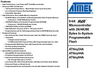
Hello Microcontroller / Atmel AVR ATtiny44A datasheet
A microcontroller is a small computer on a single integrated circuit containing a processor core, memory, and programmable input/output peripherals. It is different from a microprocessor in that a microcontroller includes a CPU, a fixed amount of RAM, ROM and other peripherals all embedded on a single chip.
I am using the Atmel AVR ATtiny44A in the Electronics Design assignment and its datasheet is on this document (.pdf). There is a curious think about the real meaning of the AVR acronym, read on Wikipedia
There is a guide of the pins from the High-Low Tech Group at the Media Lab:

I also found really interesting this guide because explains in a simple way how microcontrollers work Beginning Embedded Electronics - 1 / Lecture 1 - Background and Power Supply
Ingredients
Physical stuff (Atoms)
Digital stuff (Bits)
Instructions to program in C using GNU Make and avrdude
Steps
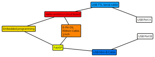
It is necesary to conect all the components as indicated on the diagram.
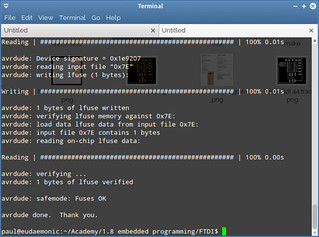
Run the following command on the terminal: sudo make -f hello.ftdi.44.echo.c.make program-usbtiny-fuses
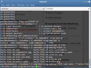
Observation: In case you are using the AVR ISP mkII, then the command is sudo make -f hello.ftdi.44.echo.c.make program-avrisp2-fuses
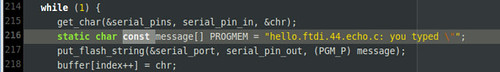
There is an error on the line 216 of the C source code, it must be added the const as on the image.
The program will respond with a Fuses OK. Thats the signal that everything went fine. If not, check your board first.
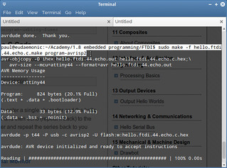
sudo make -f hello.ftdi.44.echo.c.make program-usbtiny if you are using the FabISP
sudo make -f hello.ftdi.44.echo.c.make program-avrisp2 if you are using the AVR ISP mkII
Instructions to program the microcontroller with the Arduino IDE
Steps
It is necesary to conect all the components as indicated on the diagram.
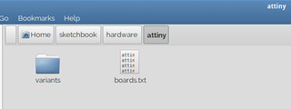
Inside your sketchbook folder create a new one called hardware and decompress all the content of the master.zip file:
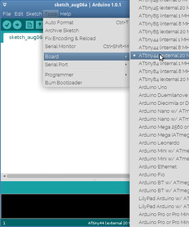
Tools-->Board-->ATtiny44 (external 20Mhz)
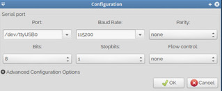
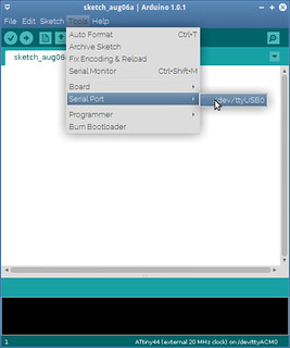
Tools-->Serial Port-->/dev/ttyUSB0 (Depends on your operating system, on GNU/Linux use ls /dev/tty* to discover your port list and select accordingly)
Tools-->Programmer-->AVRISP mkII (depends on the ISP used)

In GNU/Linux, after you try to upload the code to the microcontroller sometimes is required some aditional activities.
First create a rule inside /etc/udev/rules.d/, it can be named: 10-usbtinyisp.rules and is necesary to add this line only: SUBSYSTEM=="usb", ATTR{product}=="USBtiny", ATTR{idProduct}=="0c9f", ATTRS{idVendor}=="1781", MODE="0660", GROUP="dialout"
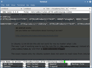
After that, execute the following command on the terminal: sudo udevadm trigger (this forum provides more related information)
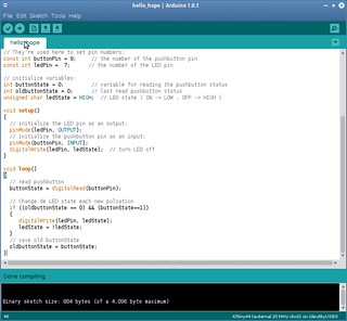
The message area from the Arduino IDE will display: Done uploading.
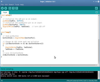

Because of the code loaded, every time the button is pushed, the LED will change it state from ON to OFF and viceversa.
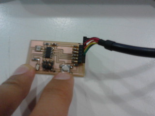
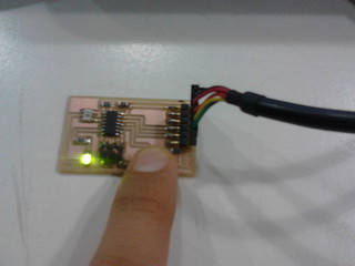
Results:
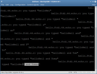
The board previously designed was programmed. The microcontroller now has a code inside that makes that every input read over the serial port will be returned to the computer using the same port.