
1.2 Computer Aided Design
Ideas
Design. (noun) a specification of an object, manifested by an agent, intended to accomplish goals, in a particular environment, using a set of primitive components, satisfying a set of requirements, subject to constraints; (verb, transitive) to create a design, in an environment (where the designer operates).(Source: Wikipedia)
Ingredients
Goals: to build a portable ECG device
Components: Circuit board, Case, Electrodes
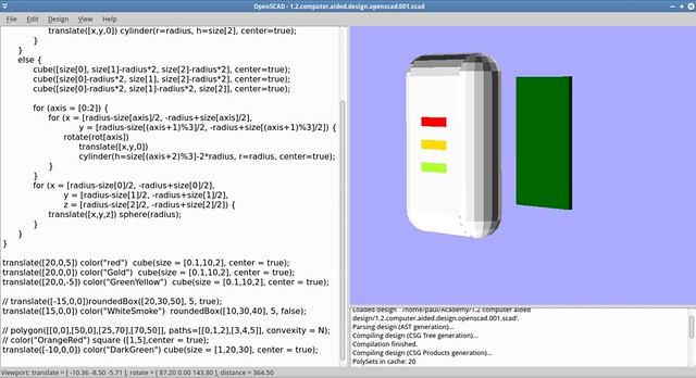
High Level 3D Design or source code nightmare
3D Design: OpenSCAD Source code
Image: OpenSCAD Design Workbench
Comments
It is interesting to see how a thing relates to its textual representation. Even when I design based on the code, and the level of abstraction required to make it make its harder to design you can actually see how the words relate to an object. Saying that, it takes much time to make in this way in comparison to other tools metaphors of work. OpenSCAD makes honor to its phrase: The Programmers Solid 3D CAD Modeller
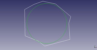
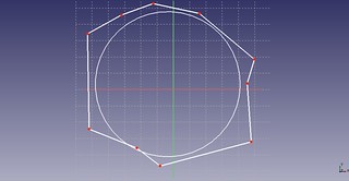
2D and 3D Design: FreeCAD
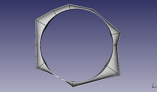
I started this design explorations learning to draw a simple object. In the first picture a circle is drawed, then several circles and a polyline are added. This requires to be confortable with the menu of FreeCAD to be able to go from draft, sketcher and part design.

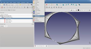
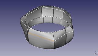
Then a 3D solid is created, in this case using the Part --> Loft menu option.

After that is possible to navigate beetween the different estandar views that FreeCAD provides.

Then is possible to create 3D forms based on 2D designs.
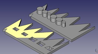
A 2D basic draw is defined.Then a pad is created based on it. The material parameters can also be changed.

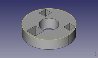

Design of the case
For the case of the ECG device a basic layout is defined. Then basic exterior details are added. In the end a video render is produced.


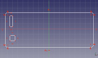
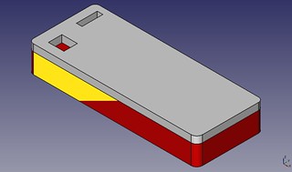
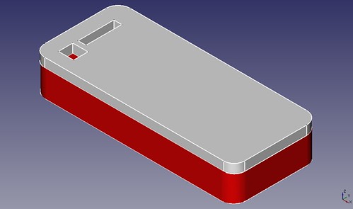
I updated the FreeCAD version, from 0.12 to 0.13. And draw a new part, wich can be obtained through a sucession of pads and pockets operations and some polishing operation: fillet. Essentially the metaphor which this program work is to add and remove surfaces of the working object.
Simulation: Paraview
I am learning about the capabilities of ParaView in order to simulate the behaviour of the material given the restrictions of temperature of the portable ECG. I think that is one of the evaluations necessary to consider: how does the components material behaviour change on time given a set of parameters.
In CAD tools, we usually model only the physical representation, but not the behaviour of the components, and making that we assume that it doesnt change. Maybe sometimes, but it is not something we can assure from the beginning. I think that a real designer must understand how the things product of his design process will behave before he builts it. Simulation provides us with that aproach.
Results
I agree with the Kokopelli tutorial if we are going to turn codes into things then code is a must.
I am very interested in the use of several tools but from the lecture and documents readen is pretty clear from me that with design will happen the same that with the ASCII, there must/will be a very low level code/estandar for 3D representation in the same way that ASCII and Unicode estandardize the digital representation of the alphabet. It makes more sense and is a very simple aproach.
Inspirations from HTMAA
Full visual journey
If you want you can go through all the process