1.15 Machine Design

3.2 : CONCEPTUAL MODELLING:

The Schrodinger's Machine has two possibilities to be materialized: 1. as a BCN CNC, a MTM Snap based clone, and 2. as a Drawbot. As a group project we will document both until a decision is made.

3.3 : DIGITAL MODELLING

3.3.1 : Physical structure

3.3.2 : Instrumentation

3.3.3 : Computation

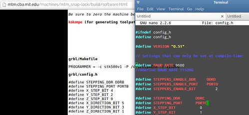
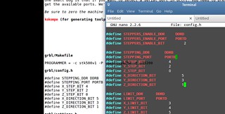
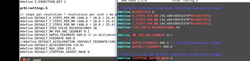
GRBL installing and configuring

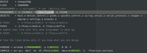
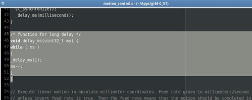
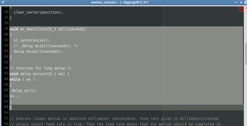
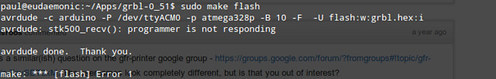
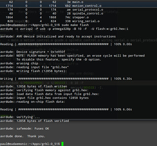
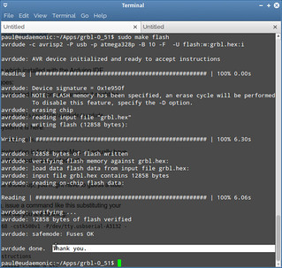
GRBL flashing into the microcontroller (ATmega 328p)

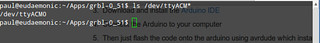
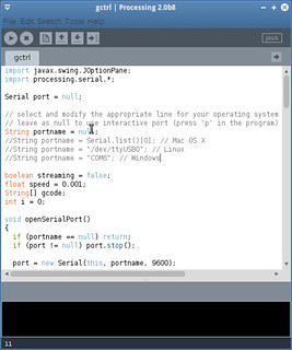
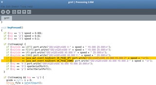
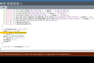
gctrl installation and configuration (using Processing IDE)

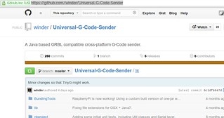
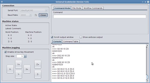
Universal G-Code Sender installation and configuration

GRBL reconfiguration

3.4 : PHYSICAL MODELLING / FABRICATION

3.4.1 : INGREDIENTS

Digital stuff (Bits)

Physical stuff (Atoms)

3.4.2 : INSTRUCTIONS

Steps

  • Step 0: Fabricate the circuit using the CNC milling machine and the soldering station. Result: Circuit board completed
  • RESULTS

    Inspirations from HTMAA

    Full visual journey


    8 nodes

    Machine design .: First run Machine design .: Second run Machine design .: Third run

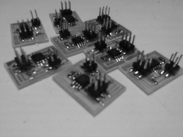
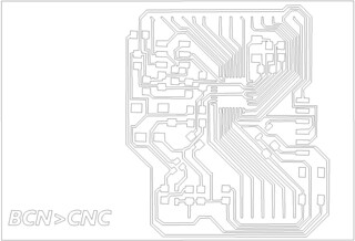
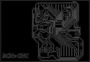
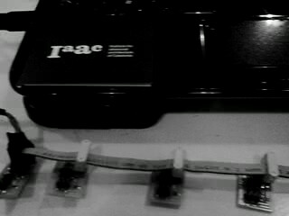
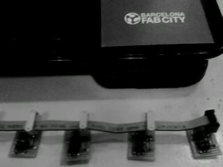
    Board milling and breaking

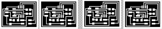
    If you want to test more than one serial bus node you can use my image modification here (is the GIMP source so you can export into PNG).

    Several boards in a run

    Ingredients

    Physical stuff (Atoms)

  • Circuits: Hello.bus.45 8 circuit boards
  • Power source: USB TTL Serial Cable. 6 way, 0.1" pitch single inline connector
  • Link intercircuits: 4-Pin DIL Ribbon Cable, 3 Inch
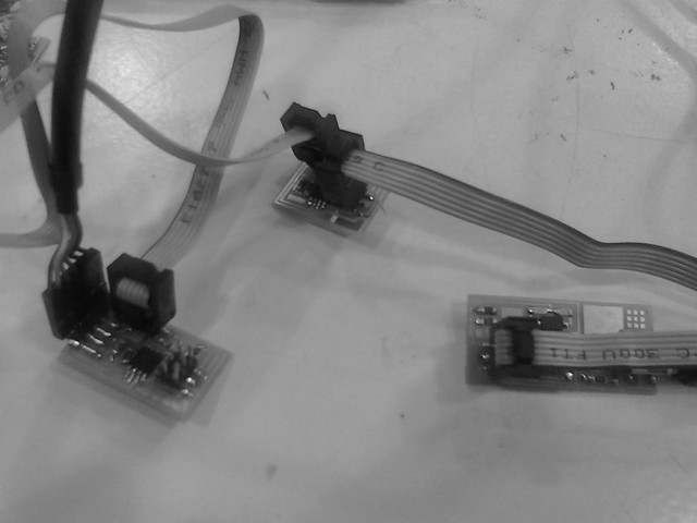
  • If you don't have a 4 pin cable, there is also a hack, you can use a 6 or 10 pin DIL cable and add 4, 6 or 10 pin DIL female headers

    Digital stuff (Bits)

  • Hello.bus.45 source code and makefile
  • Application to interface with serial port: GtkTerm, Arduino/Serial monitor, Term.py
  • Instructions

    Steps

  • Step 0: Modify the source code of hello.bus.45.c. In the line 222 add a const declaration, the final line should be: const static char message[] PROGMEM = "node ";
  • Step 1: Program the bridge circuit board (using the FabISP burn the c code into the circuit: sudo make -f hello.bus.45.make program-usbtiny). Result: Bridge programmed
  • Step 2: Program a node (using the FabISP burn the c code into the circuit). Result: Node(s) programmed (Repeat this step if you have several nodes, dont forget to change: #define node_id '0' according to the node id)
  • Step 3: Connect the bridge and the PC through the USB TLL Serial cable. Result: the network will have energy and data through the serial port
  • Step 4: Connect the nodes and the bridge through a wire (that is a serial bus network)
  • Step 5: Execute the application (GtkTerm: sudo gtkterm) and select Configuration->Port-> Port:/dev/ttyUSB0 and Baud rate: 9600. Result: Interact with the network
  • Step 6: Input the node id number. The node whose id is equal the number you input will flash twice.
  • Back to top