
1.10 Input Devices
Oompa loompa learning: massive production
Reading the tutorial Input Devices- Examples from Anna Kaziunas
This week I take an alternative approach, instead of made just one circuit I thinked that I would gain more experience if I tried to made most of the examples in order to understand and achieve a deep learning.
And I think it this new approach really works! I milled 6 boards (but pretend to do more), including 1 for a new FabISP, discarded 1 and solded 2 circuits (light & sound). I passed through all the fabrication, assembling, configuration, programming and testing processes.
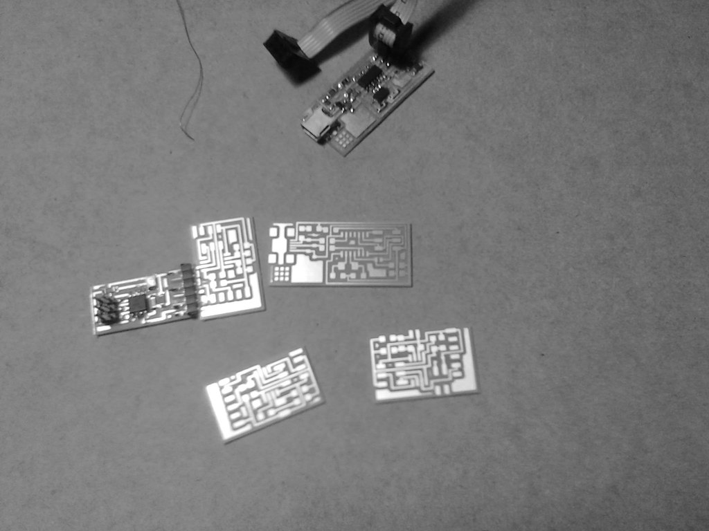
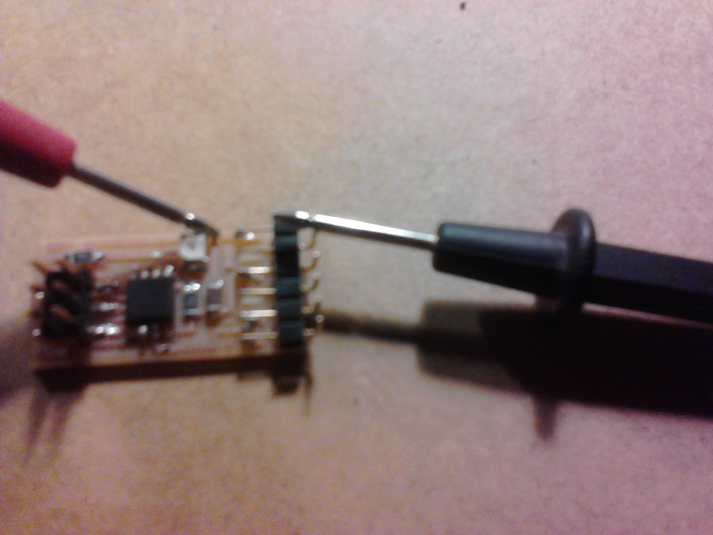
Also I maded all the possible mistakes, including but not limited to: A-not fully solded components, B-not used the multitester to test the circuits from the beginning, C-using the wrong endmill, among others.
Configuration
One of the things that happens to me is that my Fab ISP appears to not work. So instead of trying to make it work, I used the AVR mkII programmer (at this point I decided to incorpore a new component into the Fab ISP design: a LED, it is a helpfull signal to see the light).
Using the AVRISP mkII i found that I need to modify the makefiles source code (eg. hello.light.45.make) adding the following lines:
program-avrispmkII: $(PROJECT).hex
avrdude -p t45 -P usb -c avrispmkII -U flash:w:$(PROJECT).c.hex
program-avrispv2: $(PROJECT).hex
avrdude -p t45 -P usb -c avrispv2 -U flash:w:$(PROJECT).c.hex
program-avrisp: $(PROJECT).hex
avrdude -p t45 -P usb -c avrisp -U flash:w:$(PROJECT).c.hex
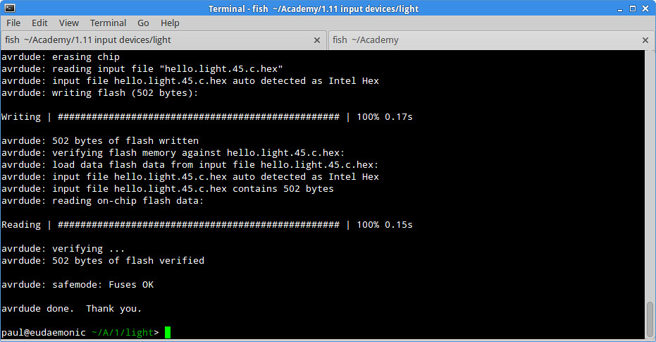
In the end the hardware was programmed using the AVR ISP mkII. The command for the program must be executed with superuser permissions
sudo python hello.light.45.py /dev/ttyUSB0
Link to the video
Full visual journey
If you want you can go through all the process