
1.6 Electronics Design
The (minimal) assigment:
Redraw the echo hello-world board, add (at least) a button and LED (with current-limiting resistor), check the design rules, and make it.
Electronic Design
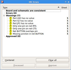
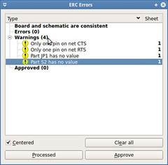
- Electrical Rule Check Test the circuit for conection errors at electrical level: wires, component conection, values, names, etc. More information can be found on this at link
- Design (for manufacturability) Rule Check Test the circuit for errors at a manufacturing level: layers, distances, sizes and shapes among others previouly defined at Eagle Design Rules. More information can be found on the at
The goal is to have the least errors and warnings. Each iteration will help us to do it.
Ingredients
Physical stuff (Atoms)
- Copper Clad Laminate Board ,PCB.
- Production technique: sustractive manufacturing. Tool: CNC Router (Roland Modela)
- Drilling bits: 1/32 + 1/64 inches
Digital stuff (Bits)
- CAD software (to design the model): Cadsoft Eagle PCB Design Software , Kokopelli
- Machining Software (to send the model): Fab modules
Instructions
Steps
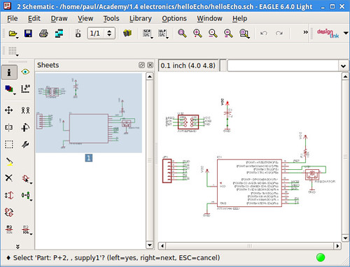
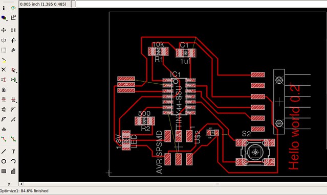
The task is to redraw the hello echo board, adding a button, a LED and a resistor. First at the schematics:
Observation: There is a pattern in relation with the design grammar previously mentioned. There are rules that possibly can be abstracted in a new unified model that link electronic and geometry design. I will try to see and define at least one rule.
It will be necesary to route all the components. It can be made by hand with the Wire tool or automatically by the Autorouter tool (Tools --> Autorouter)
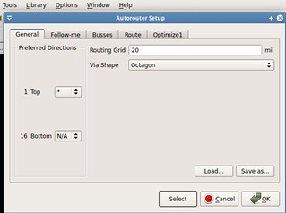
In this case the board was completed using first the Autorouter and then completing the paths with the Wire.

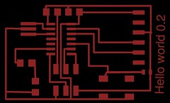
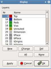
Remember to only export the top layer (on the Eagle board design screen: View --> Layer settings --> Top)
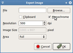
Also remember to select the Monochrome option on the Eagle export image dialog (File --> Export --> Image)
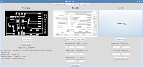
From format: image(.png) to process: Roland Modela(.rml)
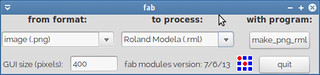
Select the drilling bit: 1/64 to mill the circuit traces and 1/32 to cut the board
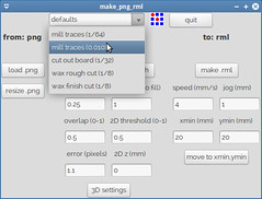
Load the circuit board traces image into the fab modules
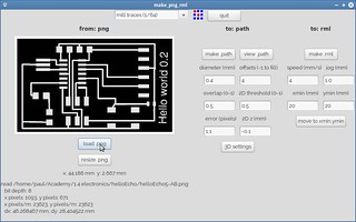
Push the make path button in order to generate the path that will follow the drilling bit.
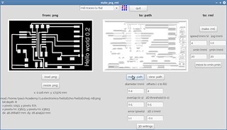
Push the make path button in order to generate the path that will follow the drilling bit.
The CNC machine will start to mill the circuit.
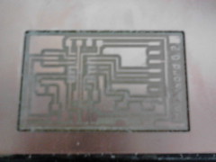
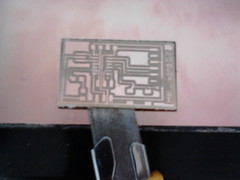
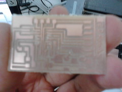
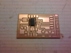
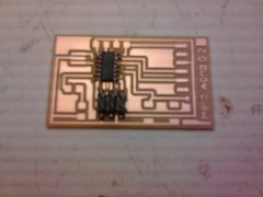
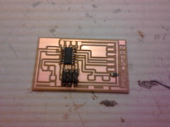
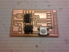
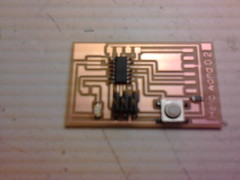
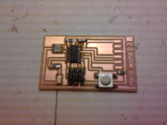
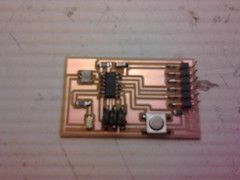
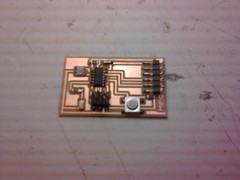
Results:
Circuit
It has been added a LED, a button and a resistor into the circuit. Also the Electrical Rule Check (ERC Tool) has been applied into the circuit design to test the schematics design for electrical errors.