
1.18 QUORE: Project Development
DISCLAIMER: If you want to fab it. We make no claims about the safety of the below techniques or about their appropriateness for any purpose. Use at your own risk and consult experts on electronics safety.
If you are looking for the other project: NOISESTORM go to its page
The assigment:
work on your machine and final project, documenting your progress:
2. : QUORE
2.1 : OVERVIEW
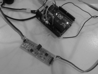
A portable low-cost EKG device based on the FabECG.
Will be required to make a circuit board and a (plastic, cardboard or wood) box. This requires the use of computer aided design, computer controlled cutting (laser cutting), electronics design, electronics production (board milling)
The estimated cost will be about 40 USD dollars in materials, plus the cost of the process (machine time in laser cutting, CNC milling, etc) and the cost of the design (in man-hour). It is necesary to make iterations focusing on the minimum viable product which in this case is a box and the circuit board.
2.2 : CONCEPTUAL MODELLING:
2.2.1 : Physical structure
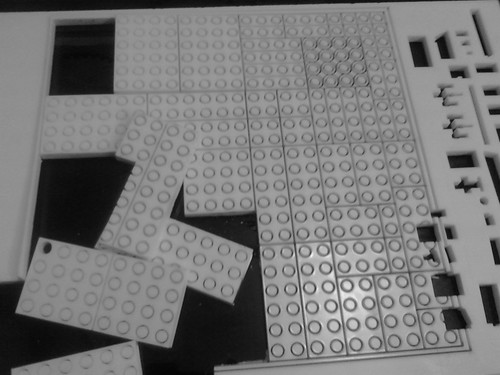
It is really necesary to design one piece structures in order to make this project or any object?. I think that it is not necesary, because if in the end everything are comprised of atoms, we can resemble this using interchangeable parts, similar as in architecture is the use of space frames to achieve complex structures. The main benefit is error correction, because in case of an error we can simply change one small bad piece instead of discard a complete work. Thats how nature work, and it seems to work well.
This idea is similar to what I have intended to make in Computer Controlled Cutting, which was to generate a 3D structure from a 2D design grammar. In this case the grammar has to be thinked natively in 3D
There are some similar open source kits,
2.2.2 : Instrumentation
I am using the FabECG v6m design of Charles Fracchia and Adam Marblestone
There is several concepts to understand the data, there is an interesting essay written by Abdallah Ishbeata describing the physiology fundamentals and the concepts behind the circuit design.
2.2.3 : Computation
There are several options to use for the visualization of the information, I intend to use: Xoscope and some ad-hoc coding for Arduino, Processing and Pure-Data.
2.3 : DIGITAL MODELLING
2.3.1 : Physical structure
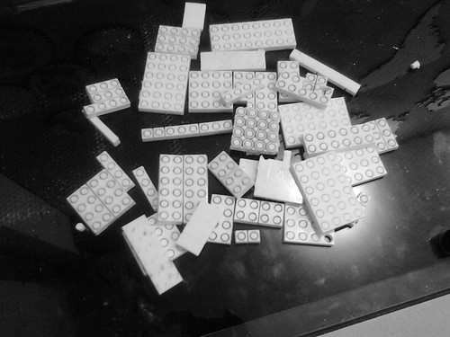
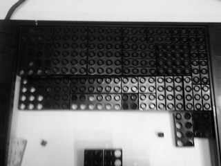
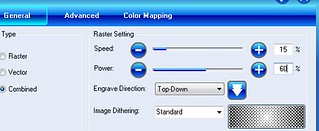
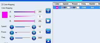
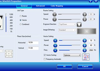
I will use produce an old-fashioned box for the circuits. The experiments with the pieces has not worked at this time.


2.3.2 : Instrumentation
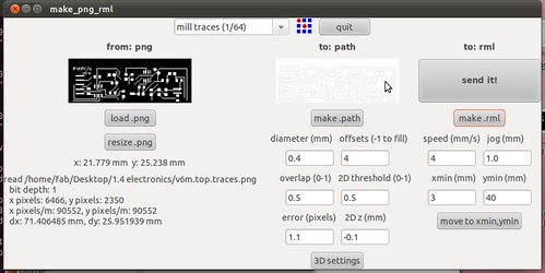
There is the circuit design from FabECG, in the schematic design there is no change.

In the board design, the only change posible was the customization of the name.


Because of the lack of electrodes and the constrain that most of the parts has to be self fabricated i will use a design from Engineering from Change http://www.instructables.com/id/How-to-make-ECG-pads-conductive-gel
2.3.3 : Computation
There are several ways to visualise the information:


2.4 : PHYSICAL MODELLING / FABRICATION
2.4.1 : INGREDIENTS
Basic materials from inventory
Digital stuff (Bits)
Physical stuff (Atoms)
2.4.2 : INSTRUCTIONS
Steps


After the test I made and because the first board didnt appear to work, a new one was milled and solded.

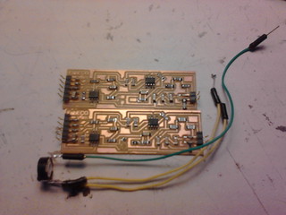
One of the things changed in relation with the circuit design was the use of a different Trimmer. For the recording of the video, a 0.75M trimmer was used and of a different technology (THT).
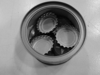
The electrodes were developed using a tutorial from Engineering from Change in Instructables.


RESULTS
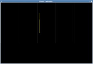
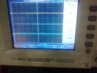
The QUORE circuit board is being tested. The signal showed is the reading of the inputs of the electrodes amplified through the FabECG circuit and show in the oscilloscope.
The FabECG circuit is design of Charles Fracchia and Adam Marblestone. Because at the time of the experiment an 1M trimmer potentiometer TRIMMER 1M OHM 0.25W SMD, as defined in the circuit couldnt be adquired it was replaced by one of a different technology (Through-hole technology) with a 0.75 M value.
The electrodes were developed using a tutorial from Engineering from Change in Instructables: http://www.instructables.com/id/How-to-make-ECG-pads-conductive-gel/
The power supply is a KAISE HY3003D-3 machine and the oscilloscope is a PROMAX OD-581. The patterns showed in the oscilloscope are consistent with similar readings of ECG devices, although several parameters and conditions are not controlled at this point. http://www.ecglibrary.com/norm.html
One of the configurations needed to make in the next experiment is to change horizontal values (frequency of readings) in order to match an standard ECG machine.


FINAL IDEAS
In this project most of the items worked, even the ones that I adapted. I learned not only how to design and create a device but also to test it continously, and made iterations of my ideas by changing variables.
I'm considering to make two things in the future: to transform the device into a platform in order that other boards can be designed around it; and to send all the data to the cloud so it could be analyzed there.
4. CREDITS AND ACKNOWLEDGEMENTS
Credits
Acknowledgments
Inspirations from HTMMA