Index
- 3D design - Computer-aided design
-
Structure
- The incubator box - CNC + 3D printing
- The bed - CNC + molding & casting
- The legs - CNC
- The user interface - Laser cutting
-
Electronics
- Switchboard - Networking & communication
- Control panel - Input/Output devices
- Relays - Output devices
- Temperature controller - Input/Output devices
- Bluetooth - Networking & communication
- Android - Interface
- Result
- Analysis
- Files
This page describes my final project for FabAcademy 2015. The document hierarchy is based on the different areas and techniques used to develop the project.
3D design
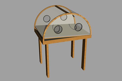
The incubator design has been evolving for the las 6 months. At first, the design was a dome-shaped incubator with four legs.
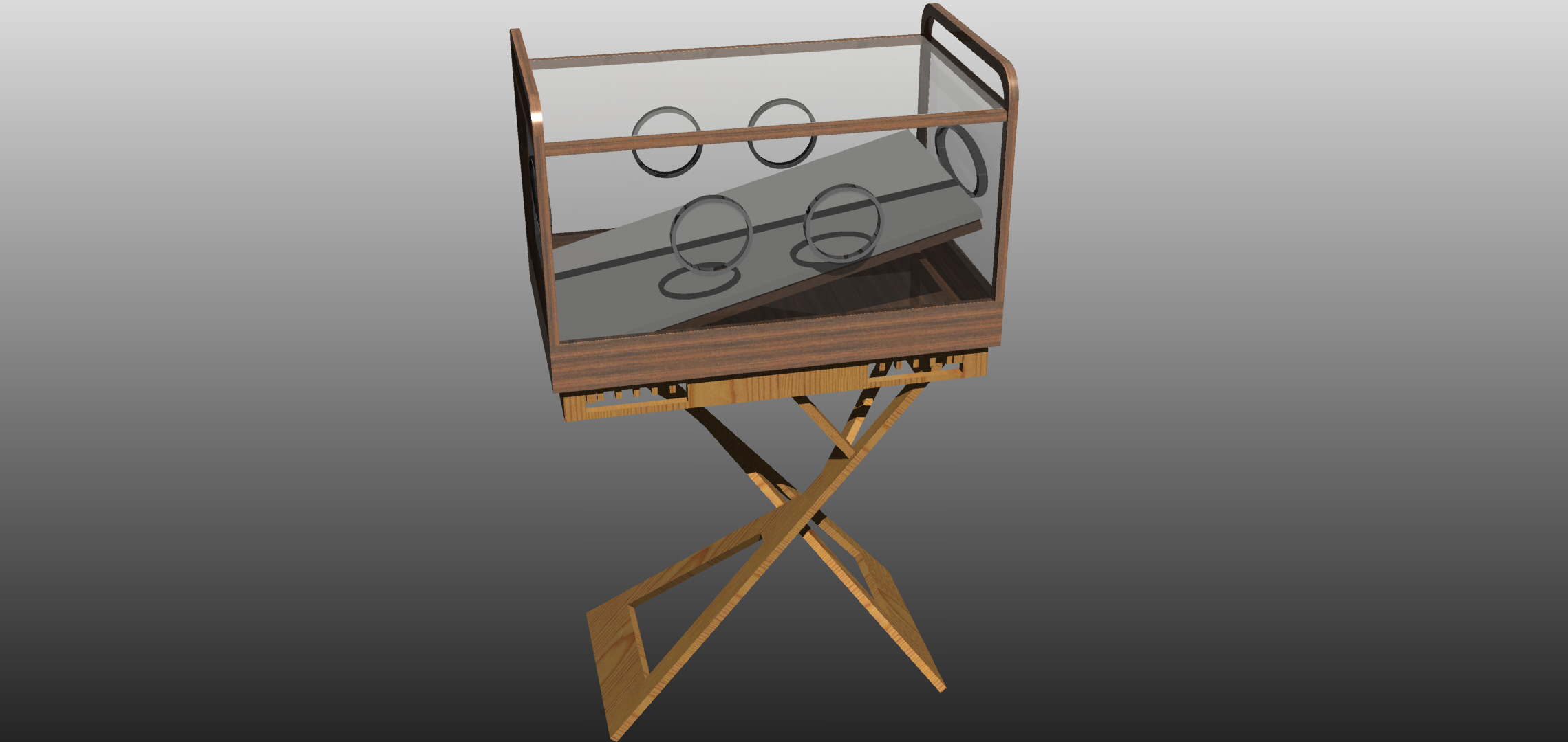
Later on, I realized that using a dome shape was not the best approach; the medical staff need space to handle the baby. So I redesigned it with two separated parts: the legs and the incubator box.
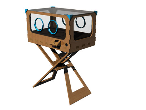
I loved the new design, but it was not robust enough. So I decided to iterate over the design once again. This time the legs and the incubator box came together.
Structure
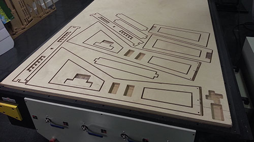
The structure of the incubator was cut using a CNC machine. Several materials and techniques have been used during the process.
The incubator box
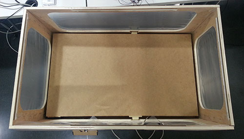
The incubator box is the most important part of the design. It must be robust and useful for the medical staff in spite of being made using low cost materials and the design must be as simple as possible to be reproducible anywhere in the world.
It is made of two materials:
- 1cm thick plywood for the chasis.
- Flexible plastic for the "windows" of the box.
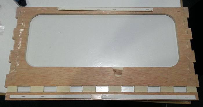
As seen above, each wall is covered by a thin layer of flexible plastic. To avoid holes between the wood and the plastic the latter is folded around the board and stapled to the inner side.
The notches seen in the photo allow the chasis to be built using a press-fit technique. Whereas the plastic is hold using clamps. The clamps allow the medical staff to change it easily without the need of technical personnel.
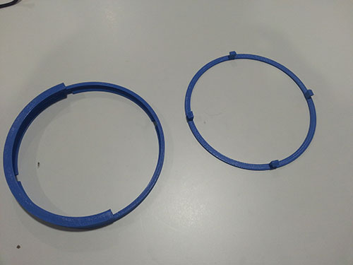
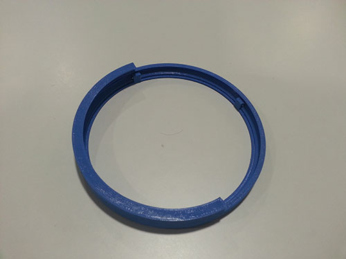
Using flexible plastic to cover the windows of the box, gave me the chance to add some hand holes to interact with the baby, using pairs of 3D printed rings.
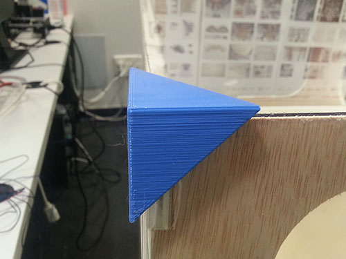
The ceiling of the box is also made out of transparent plastic, but instead of being flexible, it is a rigid one. It is secured to the ceiling of the incubator by 3D printed corners. This approach allows removing it easily.
The base of the incubator box is directly in contact with the tilting legs. The base of the box closes the incubator box using a press-fit technique. But instead of using 1cm thick plywood, I used 3cm plywood. It makes the incubator more robust and allows creating some notches for the different positions of the legs.
The bed
Inside of the box there is another important structural part: the bed. It is a wooden board hold in position by the pieces built during the molding and casting week. The edge fits inside the notches of the long sides of the incubator wall.
The shaped shaft joint allows the staff to remove the bed easily as well as to tilt the bed using a mechanism inside the box. A good example is the mechanism designed for the mechanical design week assignment. This design is not included in the final project design because I wanted to drop the price of the device as much as possible, and I consider it an unnecessary feature. It might be included in the future.
As seen, the fulcrum is not centered. It is slightly shifted towards one side. I did that to allow the bed to be tilted 15º without hitting the base of the box. On the other hand, it needs to be held horizontally. Currently the bed holds in position lying the far side of the fulcrum on the top of the fans.
The legs
As seen in the project evolution page, this part has evolved. The legs make possible to change the height of the incubator box, and allows medical staff to tilt the bed [0º, 8º and 15º]. To do that, each leg consists of two parts:
- The bigger one is fixed to the incubator base by hinges.
- The smaller one has an adjustable joint with the bigger one without using hinges or other materials. This feature allows both pieces to change their relative angle. It can fit inside any of the three notches located on the bottom of the incubator box.
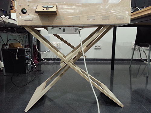
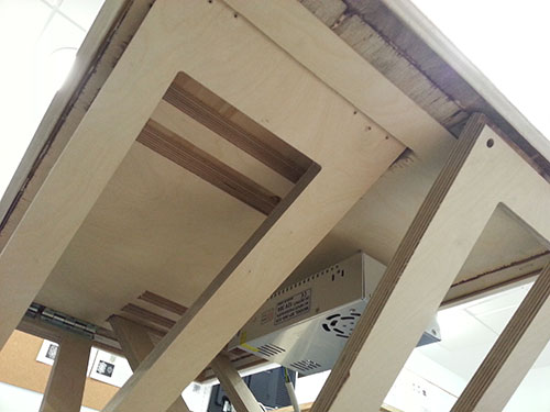
The legs have been cut using the CNC machine.
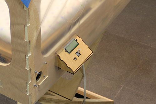
The user interface
On one side of the box, there are two holes:
- The rounded one allows the air to flow in and out of the box. If medical staff want to heat the incubator, cold air will be ejected. However, if we want to cool the environment inside the incubator, hot air must be ejected.
- The second hole has some notches. These notches allow us to attach the control panel to the incubator box. This structure is made of 3mm MDF and cut with the laser cutter.

The control panel is rotated 30º for better ergonomics.
The control panel board (which will be defined later) is held on to the structure using two M3 screws and supported by a piece of wood below the rotary switch to beare the clicks of the medical staff.
Electronics
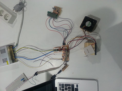
I wanted the incubator to be as inexpensive as possible. I decided to develope a modular design for the electronics. The design, that fits Nikki's (Benin) medical staff recommendations, must be able to measure the temperature and the humidity inside the box and, if the temperature differs form the targeted, the circuitry must react to reach that value. Therefore, this design will consist of three electrical modules:
- Switchboard: this is the brain [controller] of the incubator. It receives information from other circuits, analyzes it and generates a response.
- Control panel: small circuit that acts as an interface between the incubator and the medical staff. It is provided with an LCD display, a reset button, an RGB led and a rotary switch.
- Temperature controller: this circuit has the ability to measure temperature and the humidity. Despite it being designed to drive a water pump, the first prototype won't have that feature.
Instead of using just C to program the boards I decided to start using C++ code. This decision was driven by the code reusability concept. So I could reduce the excessive amount of constants defined on each program. I cannot assure this, but I think that C++ code needs more space inside the AVR microcontroller to be executed.
Compiling C++ code is quite easy. Instead of invoking avr-gcc, avr-c++ must be used. In spite of that, I realized that the C++ AVR implementation is not complete, so I had to implement some methods to instantiate classes:
Every board is designed using a ATmega168A microcontroller with an FTDI programming interface.
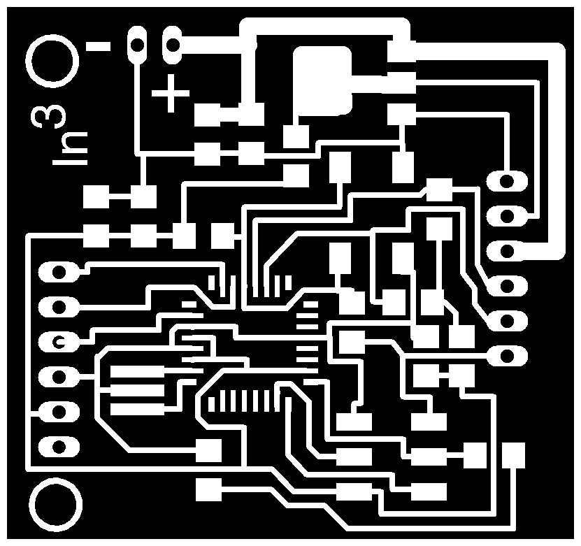
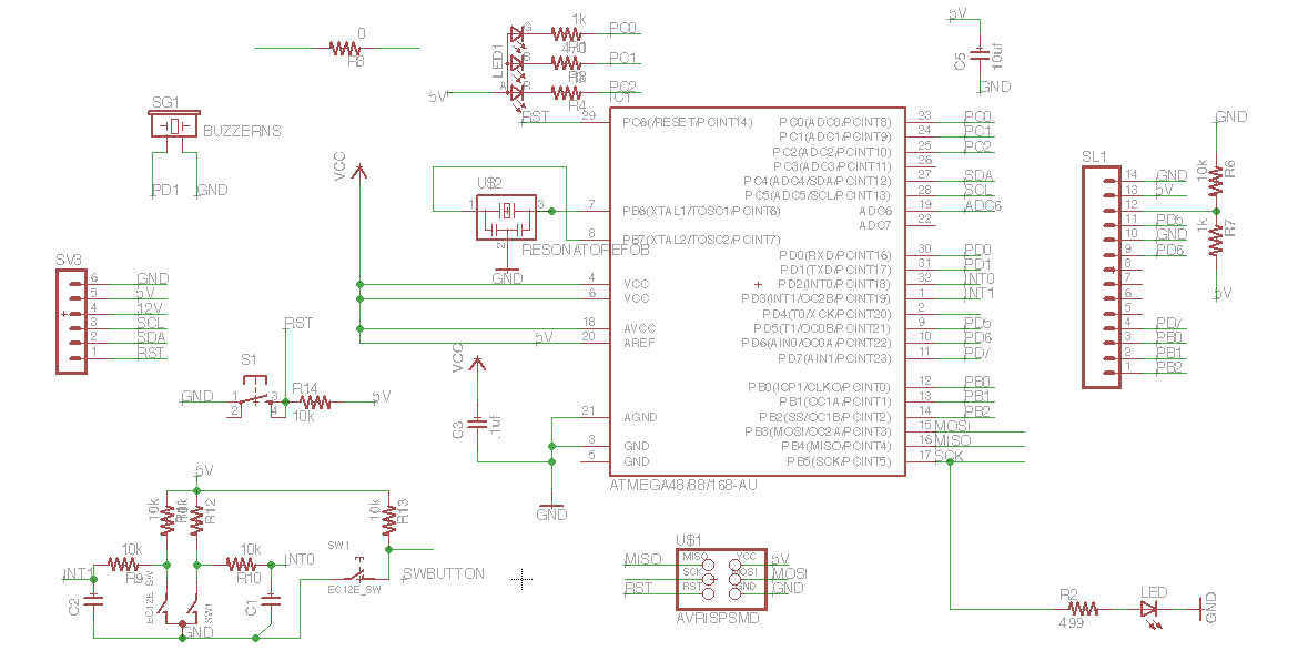
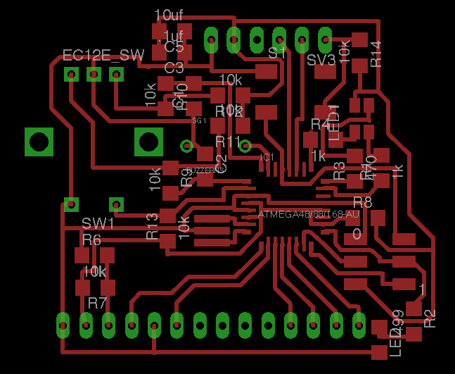
Switchboard
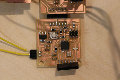
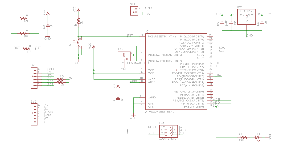
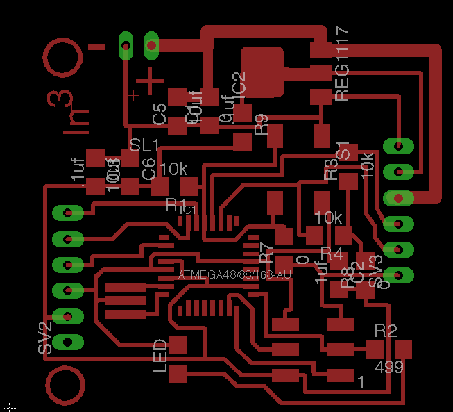
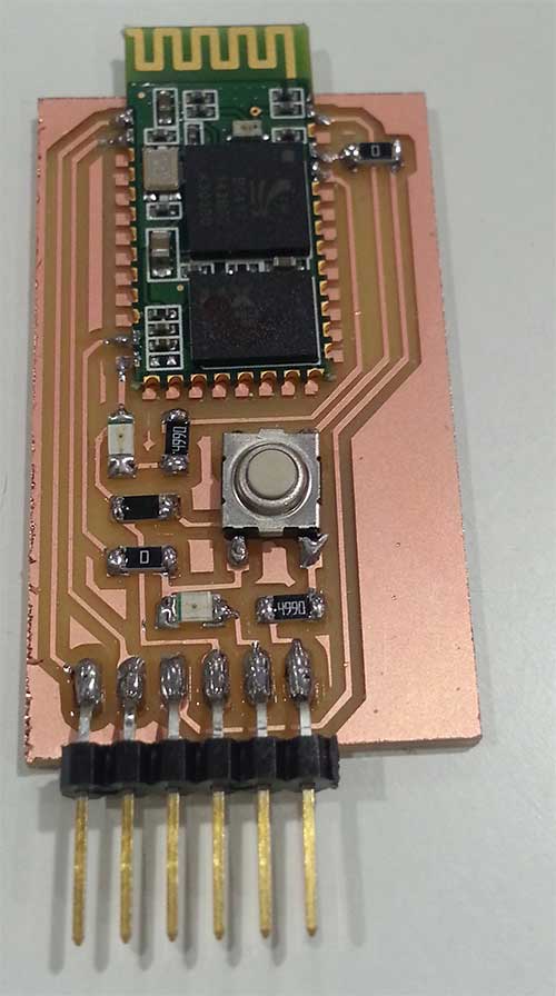
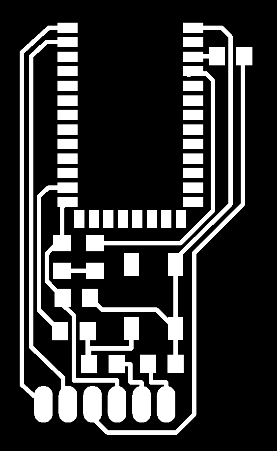
This board is the brain of the incubator. It can send and receive information from/to any other board and communicate with the bluetooth module.

On the left hand side of the circuit there is a 6 pin connector that fits perfectly with the bluetooth module designed during the Networking and communications week assignment. So the microcontroller can communicate with any device using its hardware serial port. Currently It can send the temperature and humidity data of the incubator to an android device, and receive the target temperature for the incubator from the mobile device.
On the right hand side of the board there are 6 connector pins. These pins specifications are:
- GND: propagation of the ground value.
- 5V: propagation of a stabilized 5V value.
- 12V: propagation of a stabilized 12V value.
- SCL: pin for I2C communications.
- SDA: pin for I2C communications.
- RESET: reset pin. If one circuit is reseted, all of them will be too.
Finally, this board has a 1A 5V regulator, so it can drop the input signal from 12V to 5V to feed the microcontroller and some other boards. This regulator might not be powerful enough to feed many boards, so it might need to be changed in a near future.
Control panel
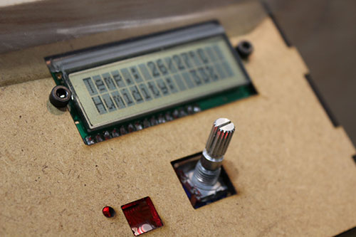
This circuit board is the interface between the incubator and the medical staff. It is connected to all the other boards through the 6-pin header. This board does not allow concatenating other boards, taking into consideration that it doesn't need the 12V signal, it can be omitted if desired.
It consists of:
- LCD display: displays the incubator temperature and humidity. Clicking on the rotary switch, the medical staff can change the target temperature.
- RGB led: output indicator that shows if the incubator is heating (red), cooling (blue) or at the desired temperature (green).
- Rotary switch: input device to interact with the incubator. It has a built-in switch. A coded output indicates if it is switching clockwise or counterclockwise. It is used to move through the menus and change the target temperature value.
- Reset button: this is the only board accessible from the outside of the incubator. Therefore, it must allow the medical staff to reset the whole device in case of strange behaviours. Once clicked, all the connected boards are reset.
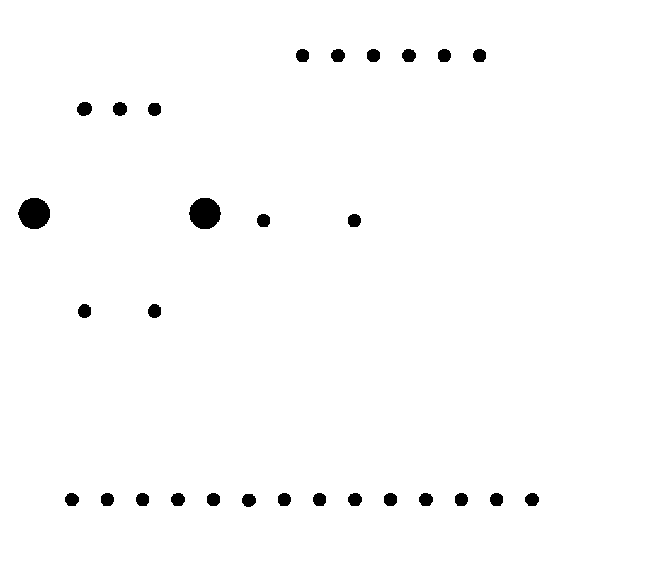

Relay circuit
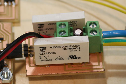
The Peltier module consumes a lot of power. At its maximum, it consumes 12V at 6A. A backwards current or any shortcut may damage the other boards. Therefore I decided to create a separated board with two circuits. The upper one is the high power circuit whereas the bottom one is the low power circuit.
Both circuits are connected using relays. The input signal of this circuit is provided by the temperature board, which will be described in the next section.
To manage the Peltier module I am using two relays. This allows me to combine the 12V and GND signals as I want:
- 12V-12V: there is no voltage difference between the Peltier poles, so it won't heat/cool anything.
- GND-GND: there is no voltage difference between the Peltier poles, so it won't heat/cool anything.
- 12V-GND: direct polarization of a Peltier module will heat one side (lets call it A) and cool the other one (B).
- GND-12V: inverse polarization of the Peltier module will now heat the B side and cool A.
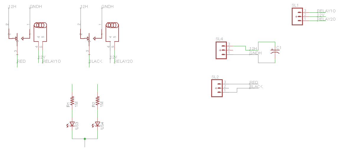
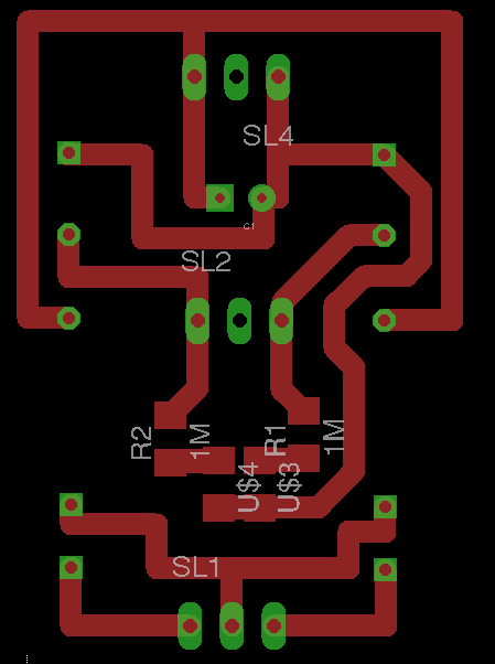
This circuit has a 2.2uF through hole polarized capacitor to stabilize the 12V signal.
This is the simplest board I designed, but not the easiest one. I am using two V23092 relays, and I couldn't find any Eagle library with that component, so I had to design it.


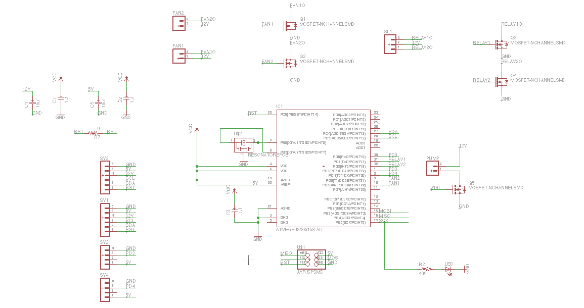
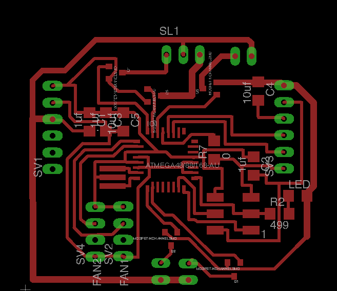
Temperature controller

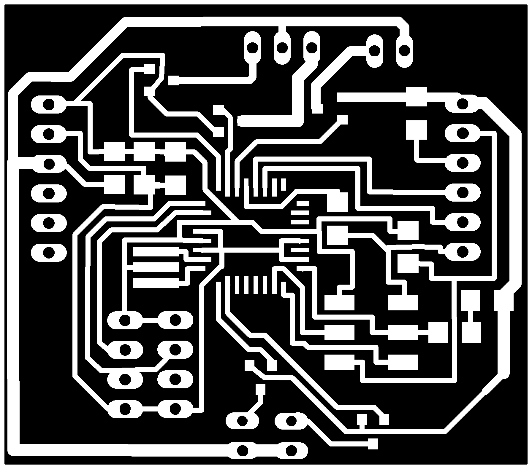
This board can manage 4 different devices [1 input + 3 output]. It also has the 6-pin header to receive the power and the information from other boards; that 6-header is duplicated, allowing circuit concatenation. I did the connections between the two 6-pin headers in the bottom layer of the board. YES! It is a two sided board.
- Input
- DHT11: temperature and humidity sensor. It measures both parameters and sends the data through a full-duplex serial port.
- Output: all output devices connected to the microcontroller must be fed with 12V. In order to do that, I used a mosfet for every output device (if the device is duplicated, the mosfet is too).
- Relays: controlling a relay is quite easy. It is a switch for high power devices, but instead of being a mechanically triggered switch, it switches with the electromagnetic field generated by a coil. If current goes through the coil, one circuit will be closed, if not, the other one will be closed.
- Fans: these devices are also turned on with a 12V voltage. Turning them on and off is as easy as changing the value of the microcontroller associated pin. But I wanted to control the spinning speed to dissipate heat/cool at the desired speed. Therefore I connected them to PD5 (OC0B) and PD6 (OC0A) so I can control the fan speed using the built-in PWM hardware interruptions.
- Pump: not jet implemented, but it should be able to control a 12V pump.

Bluetooth
The bluetooth module described during the Networking and Communication week assignment is compatible with the incubator. It can be plugged in the switchboard.

Android
As described in the documentation for the Interface and Application programming assignment, I developed a native Android App to chart the temperature of a sensor.
That App is compatible with the Incubator, but I improved it by adding a second graphic with the humidity inside the incubator.
Result
The resulting project is a functional incubator. The bed can be tilted and the medical staff can control the temperature and the humidity inside the box. It can be built in any FabLab around the world.
Analysis
What does it do?
The incubator can host one baby or two in the worst case scenario. The incubator box can be tilted using the legs and bottom notches. It controls the temperature and measures the environmental humidity. Finally, it can send the information on environmental conditions through a bluetooth module. Currently there is an Android Application that displays two charts with the retreived information.
Who's done what beforehand?
Many low cost incubators can be found on the Internet. Some of them solve specific problems, others use different approaches, a few designs are based on recycled materials, etc.
Firefly Phototherapy - MIT: this is a lovely design, very neat and simple. The problem is that, although it has one of its features, it is not really an incubator. Anyhow I decided to mention this project in this section because I consider it inspirational.
Embrace - Stanford: this is a sleeping bag that costs about $25 and allows the child to be in contact with his mom. Direct contact has been proved to be beneficial to the child's growth during the first days of life.
Clinicalresearch incubator: this incubator is incredibly well thought. It covers almost every critical aspect.
An Alternative Infant Incubator - Qingwen Kawaji: is a really interesting approach for an incubator. It combines some of the approaches seen before and creates its own version, which costs about $140.
Car incubator: this is a very interesting solution. It uses old car parts to build an incubator. The main problem of this approach is that not every the third world country has access to such amount of car parts to build it.
What did you design?
I designed the whole structure of the incubator (box + legs), the 3D printed parts and all the electronics. The designing process was iterative, and its result can be seen above and in the project evolution page.
What materials and components were used?
The incubator structure is made of wood. This material is strong and lightweight enough to move the incubator. On the other hand, the legs of the incubator allows to tilt and change the height of the machine.
In order to see through the incubator walls, I added plastic.
Finally, the electronics were made using components from the Fab Lab inventory. Currently there are only two components out of the inventory: the V23092 relay and the Peltier module.
Where did they come from?
Almost every component can be found in a Fab Lab. Therefore they can be bought using the standard FabLab supply chain. The Peltier module and the relays can be found in many electronic stores or on the Internet.
How much did they cost?
Electronics
| Item | Ref. | Qty. | Unit price | price |
|---|---|---|---|---|
| Item | Ref | Qty | Unit price | price |
| Single side circuit board stock | 3"x2" Single=16x20=320/sheet | 1 | $0.18 | $0.18 |
| ATmega168 | ATMEGA168A-AU-ND | 3 | $1.42 | $4.27 |
| IC REG LDO 5V 1A SOT223-3 | ZLDO1117G50DICT-ND | 1 | $0.25 | $0.25 |
| CAP CER 10UF 35V Y5V 1206- | 587-1352-1-ND | 5 | $0.06 | $0.29 |
| CAP CERAMIC .1UF 250V X7R 1206- | 399-4674-1-ND | 4 | $0.08 | $0.33 |
| CAP CER 1UF 50V X7R 10% 1206- | 445-1423-1-ND | 3 | $0.05 | $0.15 |
| CAP CERAMIC 10PF 50V NP0 1206 | 311-1150-1-ND | 2 | $0.03 | $0.06 |
| RES 0.0 OHM 1-4W 5% 1206 SMD- | 311-0.0ERCT-ND | 6 | $0.00 | $0.02 |
| RES 499 OHM 1-4W 1% 1206 SMD- | 311-499FRCT-ND | 5 | $0.01 | $0.03 |
| RES 1.00K OHM 1-4W 1% 1206 SMD- | 311-1.00KFRCT-ND | 2 | $0.01 | $0.01 |
| RES 10.0K OHM 1-4W 1% 1206 SMD | 311-10.0KFRCT-ND | 12 | $0.01 | $0.06 |
| RESONATOR CER 8.00 MHZ W/CAP SMD | 535-10004-1-ND | 3 | $0.22 | $0.66 |
| SWITCH TACT SMD W-GND 160GF | SW262CT-ND | 3 | $0.66 | $1.97 |
| LED RED CLEAR 1206 SMD- | 160-1167-1-ND | 4 | $0.07 | $0.30 |
| LED RED/GREEN/BLUE PLCC4 SMD | CLV1A-FKB-CJ1M1F1BB7R4S3CT-ND | 1 | $0.39 | $0.39 |
| MOSFET N-CH 30V 1.7A 3-SSOT- | NDS355ANCT-ND | 5 | $0.12 | $0.60 |
| DIODE ZENER 500MW 3.3V SOD123- | BZT52C3V3-FDICT-ND | 1 | $0.04 | $0.04 |
| 2.2uF EEA-GA1H2R2H | P15835TB-ND | 1 | $0.03 | $0.03 |
| Bluetooth module | HC-05 | 1 | $5.59 | $5.59 |
| Relay | 12VDC SPDT 1 C/O 6A SCHRACK V23092-A1012-A301 | 2 | $4.00 | $8.00 |
| LCD MODULE 16x2 CHARACTER- | 67-1781-ND | 1 | $3.80 | $3.80 |
| Rotary switch ACZ11 Series | 102-1764-ND | 1 | $1.53 | $1.53 |
| Temperature&humidity sensor | DHT11 | 2 | $2.40 | $4.80 |
| AVR header | 609-3487-2-ND | 3 | $0.42 | $1.27 |
| male hader | A34264-40-ND | 1 | $1.21 | $1.21 |
| female connector | S5491-ND | 2 | $0.55 | $1.11 |
| TERM BLOCK 5.08MM VERT 2POS PCB | ED2609-ND | 3 | $0.17 | $0.51 |
| TOTAL | $37.46 |
Structure
| Item | Qty | Unit price | price |
|---|---|---|---|
| PLA 1kg | 0.2 | $22.98 | $4.60 |
| Plywood 10mm (1.5m^2) | 1 | $26.56 | $26.56 |
| Plywood 17.5mm (3m^2) | 1 | $85.88 | $85.88 |
| Silver Tone Metal Butt Hinge | 4 | $0.65 | $2.59 |
| M3 rod 1m | 1 | $0.17 | $0.17 |
| M3 nut | 16 | $0.03 | $0.45 |
| m3 washer | 8 | $0.00 | $0.03 |
| Axial fan 50x50mm | 2 | $2.55 | $5.10 |
| PWR source | 1 | $20.00 | $20.00 |
| disipador 50x50 | 2 | $3.39 | $6.78 |
| Wood screw 3x16 | 12 | $0.02 | $0.21 |
| thermal silicone 5g | 1 | $1.90 | $1.90 |
| TEC1-12706 12V 60W | 1 | $4.00 | $4.00 |
| Silicone Wire 10 Feet | 1 | $11.94 | $11.94 |
| Audiopipe 100' Feet 22 GA Gauge Red and Black Speaker Wire Home Car Zip Cord Audio Cable | 0.1 | $10.95 | $1.10 |
| Transparent plastic (45x75) | 1 | $1.01 | $1.01 |
| high density polyethylene (250x60) | 1 | $2.00 | $2.00 |
| TOTAL | $174.31 |
What parts and systems were made?
The structure of the cradle, the legs and the electronics are the main parts of the incubator.
The electronics consist of three modules:
- Switchboard: controls the communication between modules and makes decisions.
- Temperature board: measures the temperature and humidity of the environment inside the incubator and regulates the temperature.
- Control panel board: it is the interface board between the medical staff and the machine.
What processes were used?
- 3D printing: some support and joining pieces are 3D printed.
- Computer-controlled cutting: the control panel is held by some MDF pieces in the front of the incubator.
- Computer-controlled machining: the incubator box and its legs were cut using a CNC machine.
- Molding and casting: these were used to reproduce some complex shape parts easily, for example the bed axis.
- Mechanical design, machine design: there are some notches to tilt the bed. Also, an alternative design to tilt the bed without using the legs was developed.
- Electronics & programming: almost every electronics and programming technique (if not all of them) learned during the FabAcademy 2015 was used in the project.
What questions were answered?
Is it able to increase the room temperature? Yes, it can increase the box temperature 6 degrees above the surrounding one.
Can the doctor/nurse tilt the bed? Yes, using the legs and the bottom notches.
Is it easy to use? Yes, it has a very simple interface with an LCD display and a rotary switch.
Is it cheap? Yes, the material cost is below the stablished target (300€).
Is it easily repairable? Yes, its modular design allows the incubator to be repaired without spending much money or time.
How was it evaluated?
The final product should include at least thermoregulation and bed inclination with a simple user interface. It is easily repairable and effective.
What are the implications?
An incubator prototype will be sent to the Nikki maternity in Benin this Fall. Therefore, it must be ready to be used in a real third world hospital in a few months. Two of the key points are the safety of the components and the stability of the incubator, which are good but will be improved in the next iteration.
Files
3D design
Structure
Computer-controlled cutting/machining
- in3_base_35mm.dxf - The 6 inner notches are lowered 25mm, the top and bottom notches are lowered 3mm and the frame must be lowered 10mm
- in3_box_10mm.dxf - Remove 5mm of wood from the selected areas before cutting anything. Tip: cut the inner parts first.
- in3_controlpanel_3mm.dxf - Tip: cut the inner parts first.
- in3_legs_17.5mm.dxf - The notches (red) must be lowered 8.75mm. Tip: cut the inner parts first.
- in3_bed_10mm.dxf
3D printing
- inner_ring.stl x4
- outter_ring.stl x4
- corner.stl x4