I2C [TWI]
The incubator will consist of different modules that can be connected to add features. To achieve that goal I implemented the I2C protocol with one master device and several slaves. Therefore, the master device will communicate with the tilting bed module, the temperature module, etc. through the "two wire" communication protocol.
This protocol requires two pulled-up wires (using a 10kΩ resistor), one for the clock (SCL) and other for the data (SCA). That wiring process was made using a breadboard.
Pull
The first attempt to communicate two devices was done by pulling information from the master device.
In this example I implemented a Master-transmitter and a Slave-receiver architecture. The master device sends numbers to the slave with the number of times it led has to blink. That number increases each time it is sent until it reaches a value of 10.
Master
Slave
Interrupt
The preceding code is not implementing the best approach. Meanwhile the master device can divide its time between communication time and self-executing time because it decides when to communicate; the slave device has to be wasting CPU time waiting for the master device to start the communication. In order to fix that issue I decided to use interruptions in the slave device, so it can process information when not transmitting or receiving.
The incubator brain will need to send and retrieve information from the external modules. This new code enables two ways communication:
- Master-transmitter/Slave-receiver
- Master-receiver/Slave-transmitter
The implemented program sends a number (x) from the master device to the slave. The slave blinks the led 'x' times. The slave subtract the received number to 10 and sends it back to the master device. The master device blinks the led 10-x times. Increments the number to be sent to the slave and starts again.
Master
Slave
The interaction between both FabKits can be seen in the next video.
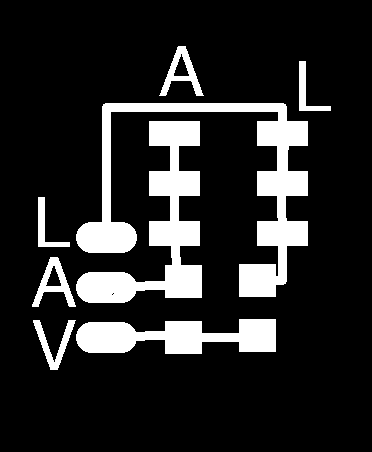
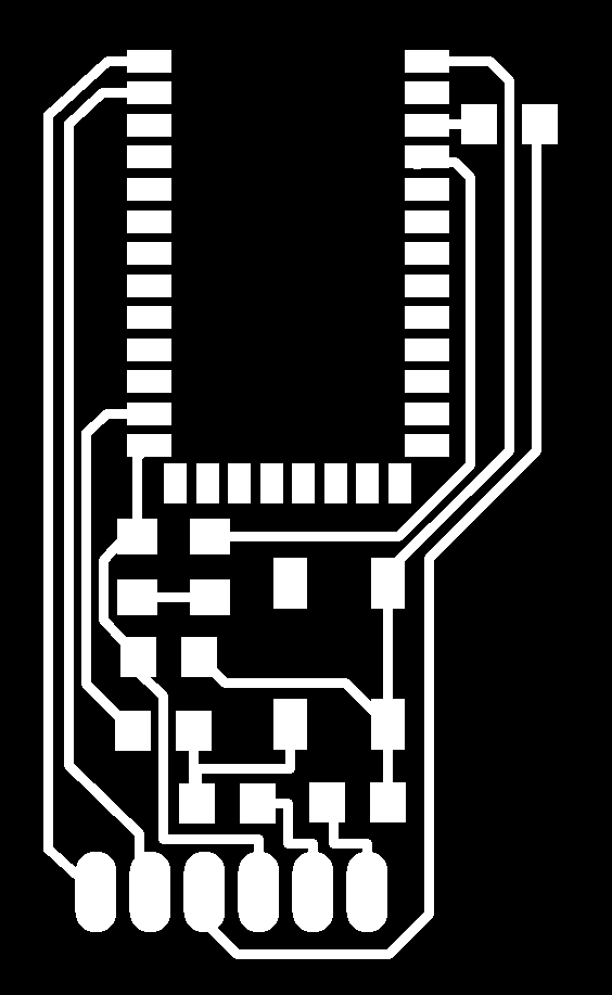
For this example I used a breadboard to do the SDA and SCL pull-up circuit. Now that everything is working as expected, I decided to create a small PCB circuit that allows connecting 4 I2C devices. The master or any slave can be connected to any port, But I suggest connecting the master device in the independent connection.
Once welded the result should look like this:
Bluetooth
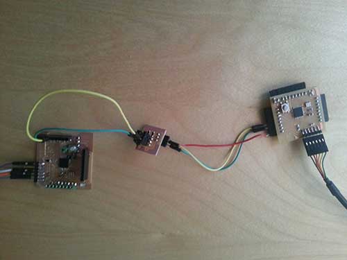
Despite of the low cost nature of the incubator I am designing, I decided to add an "optional" module to control wirelessly the machine. In order to do that I connected a HC-05 Bluetooth module to my FabKit through the USART port and tried to send and receive/send information from/to a cellphone.
To achieve that goal I recycled the code and the design of the control panel shield but, instead of connecting the FabKit to the computer using the FTDI cable, I fed the circuit using the power supply built a few weeks ago. Doing that I could use the TX and RX ports of the FabKit to communicate with the bluetooth module at 9600 bauds.
I also had to design a board to connect the HC-05 to the FabKit (using for example a breadboard).

Once welded it looks like this:
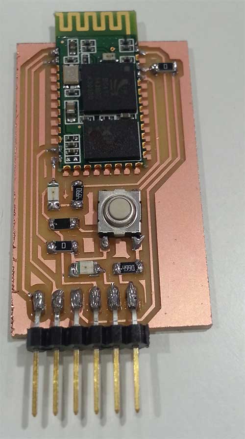
This board has a button to pair the device, a led that indicates whether is powered on or not and a second led that blinks depending on the state of the bluetooth module. It has 6 output pins, but just 4 of them are mandatory: GND, 5V, Tx & Rx.
Learning how to communicate using a bluetooth interface, I modified the control panel code. It shows the position of the joystick in the first line of the screen and sends that information through the bluetooth as a string. If the connected device sends information to the AVR, it will be displayed in the second line of the LCD display.
In order to compile and load this code into an AVR the libraries serial.h and defitions.h must be located in the folder ../lib/. Those can be downloaded from the input devices page.
In3
The incubator has 3 different boards. This approach might seem unnecessary at first glance, but the goal of the project is building a low cost incubator and, in order to achieve that goal, I designed it as modular as possible. Therefore If you want to build your incubator without the control panel board and controle it using the bluetooth connection, you can do it.
There are 3 types of networking communication:
- I2C protocol to interact between boards.
- Bluetooth through the ATmega168A serial port.
- Serial full-duplex communication to interact with the DHT11 sensor module.
The boards and code of this two input devices can be found in the final project page.