February, Tuesday 19th 2013
Assigment: Assemble and Program the FabISP
This week we started Electronics production. I was very excited since I have always been interested in making this kind of things.
I had little experience before, I have soldered some things but never things so small, so this was going to be an interesting challenge.
In this link you will find the contents of the class we had last Wednesday.
Here is the tutorial with all the steps.
We were to choose a FabISP circuit design from former FabAcademy students. Here the design options: David, Andy and Valentin.
There is also available two more options of the hello.ISP.44 boards by Neil.
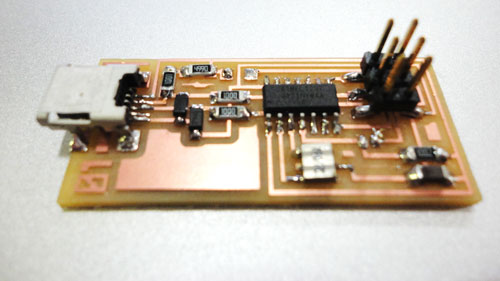
Here some pictures of the options.

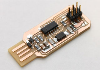

David
Andy
Valentin

hello.ISP.44
At first I decided to make Valentins design, but at the end I used the hello.ISP.44.
Here you will have 2 options as well. One uses a Crystal ( the one in the picture above) and another option with a 20mhz resonator.
Of course I didnt know this at the beginning, I noticed this when beginning to think how solder the components.
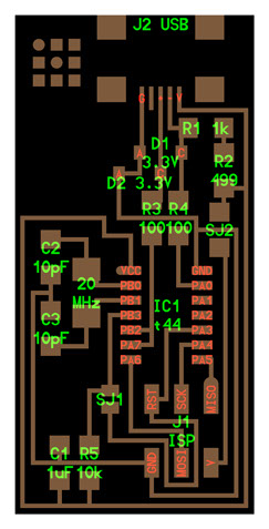

with Crystal
with Resonator
Milling the board
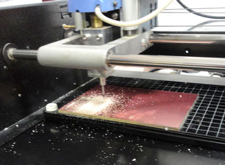
To mill the boards we used a Roland Modela milling machine. In the FabLabs we will use this machine to mill the boards as well as to mill molds. That will be on Week 07.
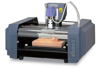
So after deciding which deisgn I wanted to do, I downloaded the .PNGs to mill.
You will need the Traces and the cut out. This means that with one file you will mill the inner traces and the other outer will cut out the board.
The inner traces have to be milled with a 1/64 bit and the cutout with a 1/64.
For better or worse I decided to use the Resonator version of the hello.ISP. I downloaded the PNG files but decided to make a little personalization, instead of the Center for Bits and Atoms logo, I just put a small numerical 01. Maybe I was pesimistic since I thought I will have to mill several boards before I get it work....01,02,03... and so on. Luckily V.01 worked just fine for me.
I edited the PNG with Adobe Photoshop.
Here the PNG files.

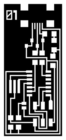
Traces
Cutout
We used FabModules to control the Roland Modela. Input is the PNG and output .rml
Just check you are selecting 1/64 bit for the traces and 1/32 for the cutout.
Next step will be to set your 0,0 origin and your Z axis. This procedure should be done every time you upload a new mill setup.
Just make sure not to modify your X and Y axis when changing from tracing to cutout. The origin should be the same as to overlap correctly both PNGs.
A good offset parameter is between 4 and 6. Thats all the parameters you should modify, all the rest leave it as default.
We are going to mill FR1 (phenolic paper) boards. Thats a copper thin plate fixed to a paper based rigid board.
There are other materials to make boards as well. You can go for flexible PCB boards using copper tape for example.
So, I went for it and started milling.
Here the results.


Traces on FabModules
Cuout on FabModules

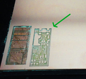
Milling the inner traces
Traces milled, ready to mill the cutout

Board ready to be stuffed
Milling the cutout
Soldering the components
Having the board ready (this was the easy part), I began to solder the components.
Luciano taught us some techniques depending of the kind of component.
A useful advice is to always have the board map near as to check you are soldering them in the right way.
Most of the components doesnt have polarity, but some do. The Diodes and the microprocessor are the ones who do. Doble check on them before fixing them to the board.
- Components marked with an "R" (R1, R2, etc) are resistors. Here is a handy SMD (surface mount) resistor code calculator.
- Components marked with a "C" (C1, C2, etc) are capacitors.
- J2 USB is the mini USB header
- IC1 t44 is an attiny44a chip. There is a little circle on the chip that should be facing to the top left (if your board is oriented in the same direction as this diagram. Look at the datasheet for the pinout.
- The resistors and capacitors (on this board) do not have polarity.
- Diodes have polarity the "C" or cathode end is marked with a tiny line. Place the side with the line on it over the "C" side pad in the diagram. You may need a magnifing glass.
- The components marked SJ1 and SJ2 are solder jumpers.
- SJ1 can be bridged with solder.
- Put a 0 ohm resistor over SJ2 on this board
So considering all this, I started soldering. The USB port was the trickiest, but luckily I solder it in the first try.
And here the results:

Board V.01 with all the components soldered
There are two jumpers in this design. This are needed to upload the firmware correctly the first time. When yo manage to upload it you should take them off. I decided to use a small piece of cable to make one of the jumpers since there was a trace passing beneath. It worked just fine. For the other jumper I just added some solder material, a small amout will be enough since you have to undo this connection later on.
"Smoke Test" : Green Light
Plug the FabISP into your computer via the mini USB cable and if you get a green light, you are good to go. Luckily I got it so I was ready to upload the firmware.
This are the possilble results if you are using a ATAVRISP2 Programmer:
Green Light: means that the header is soldered correctly, the board is getting power and the programmer can sense the microcontroller.
Yellow Light: means that the board is getting power, but most likely the 6-pin programming header is not soldered correctly (re-flow your solder joints / check for cold joints, check for shorts).
Red Light: means that the board is not getting power - check for shorts.
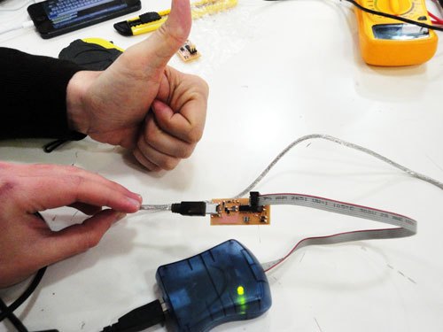
Green light : Good to go
Programming the Board, Uploading the firmware.
Jose Pablo, a FabAcademy classmate, did a great job helping us with every step of the process and since he already finished and programmed his board, we decided to program my board with his. The other option is to use the ATAVRISP2 Programmer.
So we went for it!
But before doing nothing you have to install some software in your computer. You will need:
- Avrdude (for programming)
- GCC (to compile C code)
To get avrdude and GCC on Mac OS:
1. Set up your Paths
Follow this tutorial: http://www.ladyada.net/learn/avr/setup-mac.html
Begin at "Mac Setup - Paths" heading and stop at the heading "Option 1. AvrMacPack".
2. Download and Install Crosspack AVR - Has an installer.
3. Get Make (via XCode) - If you do not already have XCode installed - Get the install disks that came with your mac and install the developer tools. If you are running Lion - you can download XCode here. http://itunes.apple.com/us/app/xcode/id497799835?ls=1&mt=12
Download and Unzip the Firmware:
Download the firmware (right click on the link below and save it to your desktop): http://academy.cba.mit.edu/classes/embedded_programming/firmware.zip
Open terminal navigate to the desktop:
cd ~/Desktop/
Unzip the firmware.zip directory:
unzip firmware.zip
Move into the newly created firmware directory on your desktop
cd ~/Desktop/firmware
Edit the Makefile:
Mac: Just click on the file called "Makefile" in the firmware folder to open / edit it.
Ubuntu and Mac:
A window will open containing the Makefile. Go to the line that says:
#AVRDUDE = avrdude -c usbtiny -p $(DEVICE) # edit this line for your programmer
AVRDUDE = avrdude -c avrisp2 -P usb -p $(DEVICE) # edit this line for your programmer
- If using the USBtiny programmer or another FabISP
- Remove the "#" in front of the line with "usbtiny" in it
- Add a "#" to beginning the line with the "avrisp2" in it to comment it out.
- save the Makefile
Program the FabISP (Ubuntu and Mac):
On terminal, type in the following, hitting enter after each command.
make clean
make hex
sudo make fuse
sudo make program
You shouldnt get any errors. If so, go back and try it again. Several classmates and myself encountered some issues when compiling the Make Hex command. It seams that there some changes in CrossPack AVR. Here the solution:
http://forums.obdev.at/viewtopic.php?f=8&t=6424
Long story short, edit usbdrv.h and usbdrv.c files from your firmware folder.
Where it says PROGMEM it should say const PROGMEM. Save both files and you should be good to go.
After editing the files compiling went smooth. Here the results:


JosePablos board
My board
Final step screenshot-Make Program
If you got through all the steps correctly, now you should test if your computer recognizes your newly programmed board via a USB port.
I had no problem with this step on Mac. Ubuntu users may have some problems in this step.
To get sure it works fine:
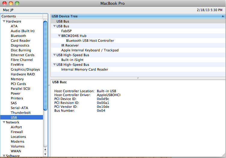
go to the System Profiler >> Hardware >> USB >> Hub:
FabISP should be listed in the hub menu. If its there, congratulations! Your FabISP device has been successfully programmed and is recognized by your computer.
Final step. Remove the jumpers.
To program other things with your brand new FabISP board, you have to remove the jumpers. In my case I removed the piece of cable and the solder material.
After this step you will want to re-check on the USB hub. It should still appear.
I also wanted to test my new board, so I programmed Franciscos board with mine. It went smooth.
Here the last picture of my board without the jumpers
