WEEK 20
Final project requirements
1) What does it do?
The Hexamodular Kinetic System is a modular, responsive facade panel that dynamically adjusts to regulate solar radiation and improve thermal comfort in architectural envelopes. Each hexagonal module contains a kinetic mechanism controlled by light sensors and embedded electronics. When exposed to sunlight, the mechanism rotates to create variable shading patterns, reducing solar heat gain while creating dynamic visual effects on the facade. The system is designed to be replicable, scalable, and locally fabricated using digital fabrication techniques.
Interactive web interface: The image below shows the web interface developed for the Hexamodular system using ESP-NOW communication. This interface allows the user to open and close the panel, activate or deactivate the light sensor, and configure kinetic movement patterns such as wave-like motion.
2) Who's done what beforehand?
This project builds upon several key references in kinetic architecture and digital fabrication:
- Kinetic Curtains by Juliana Lozano (Fab Academy 2023) - pioneering work on responsive modular systems with light sensors
- Kinetic Facades – Light Sensitive Systems program by IAAC (2020-2021) - comprehensive exploration of responsive envelope design
- Kinetic Window by Fab Lab ESAN Group (2022) - modular facade approach with integrated actuation
- Research on parametric design, CNC machining, and embedded systems from the broader Fab Academy network
3) What did you design?
Mechanical Design: A hexagonal modular cell with an internal kinetic mechanism consisting of CNC-routed MDF frame pieces and 3D-printed linkages that create rotating motion, with parametric design and CNC toolpath optimization.
3D Design & Fabrication: 3D-printed components for mounting, gearing, and actuation supports, developed through prototype iteration and additive manufacturing techniques.
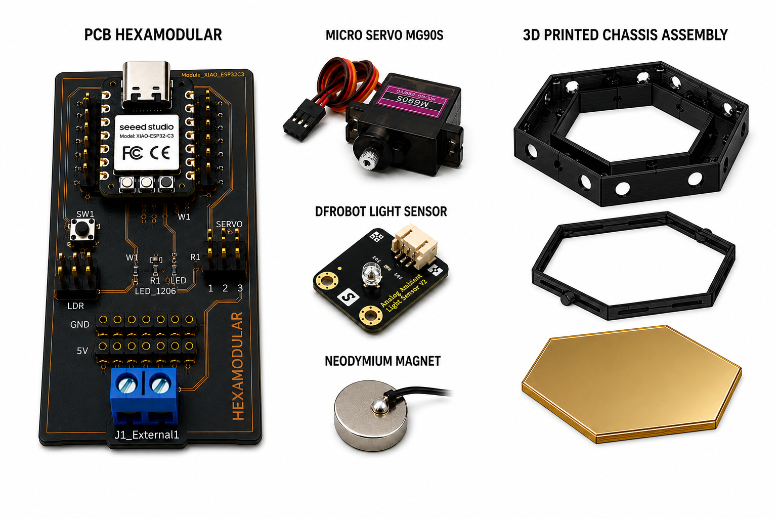
Custom Electronics: A hexagonal PCB board with a DFRobot Light Sensor Module, Seeed Studio XIAO ESP32-C3 microcontroller, servo driver, and power distribution, including schematic development and board fabrication.
Software & Control: Embedded C firmware for sensor reading and servo control, plus a web interface for real-time monitoring and interaction.
System Integration: Assembly of all mechanical, electrical, and software components into a functional module with prototype validation.
4) What sources did you use?
- Academic references on kinetic architecture and responsive facades (IAAC Fab Academy research)
- Digital fabrication documentation from FabLab Peru and Fab Academy
- Open-source libraries: Arduino IDE, Fritzing (electronics), KiCad (PCB design)
- Design precedents from project management and research documentation
- Technical specifications from manufacturers (TowerPro SG90, Seeed Studio XIAO ESP32-C3, DFRobot Light Sensor Module)
5) What materials and components were used?
Materials include CNC-routed MDF structural support, PLA/PETG printed parts, custom PCB, mirror acrylic and polycarbonate panels, and electronic components (TowerPro SG90 micro servo, Seeed Studio XIAO ESP32-C3, DFRobot Light Sensor Module, USB-C connector, and 5V power supply). The complete Bill of Materials (BOM) and cost breakdown are documented in the project records.
6) Where did they come from? How much did they cost?
Components were sourced from local suppliers in Lima (structural materials, electronics retailers) and international distributors (specialized electronics). The single module cost is approximately $41.53 USD, with a 10-module panel estimated at $421.63 USD. Material sourcing and cost analysis are detailed in the project documentation.
BOM - Single HEXAMODULAR Module
| Item | Qty | Source | Unit Cost (USD) | Subtotal (USD) |
|---|---|---|---|---|
| Seeed Studio XIAO ESP32-C3 | 1 | Seeed Studio / Fab Lab | 8.00 | 8.00 |
| HEXAMODULAR Custom PCB | 1 | Fab Lab | 5.00 | 5.00 |
| TowerPro SG90 Micro Servo | 1 | Electronics Store | 2.78 | 2.78 |
| DFRobot Light Sensor Module | 1 | DFRobot | 5.00 | 5.00 |
| Capacitors (Ceramic + Electrolytic) | 1 set | Electronics Store | 0.50 | 0.50 |
| Neodymium Magnetic Connectors O15x3 mm | 12 | Hardware Supplier | 0.83 | 10.00 |
| USB-C Connector | 1 | Electronics Store | 3.00 | 3.00 |
| Cables, Connectors and Solder Materials | 1 set | Electronics Store | 0.25 | 0.25 |
| PLA Printed Structure | 1 set | Fab Lab | 4.50 | 4.50 |
| Mirror Acrylic Panel | 1 | Local Market | 1.94 | 1.94 |
| Polycarbonate Panel | 1 | Local Market | 0.56 | 0.56 |
| Total Cost per Module | 41.53 USD | |||
BOM - Complete HEXAMODULAR Panel (10 Modules)
| Item | Qty | Source | Unit Cost (USD) | Subtotal (USD) |
|---|---|---|---|---|
| Seeed Studio XIAO ESP32-C3 | 10 | Seeed Studio / Fab Lab | 8.00 | 80.00 |
| HEXAMODULAR Custom PCB | 10 | Fab Lab | 5.00 | 50.00 |
| TowerPro SG90 Micro Servo | 10 | Electronics Store | 2.78 | 27.80 |
| DFRobot Light Sensor Module | 10 | DFRobot | 5.00 | 50.00 |
| Capacitors (Ceramic + Electrolytic) | 10 sets | Electronics Store | 0.50 | 5.00 |
| Neodymium Magnetic Connectors O15x3 mm | 120 | Hardware Supplier | 0.83 | 100.00 |
| USB-C Connector | 1 | Electronics Store | 3.00 | 3.00 |
| 5V 20A Power Supply | 1 | Electronics Store | 8.33 | 8.33 |
| Cables, Connectors and Solder Materials | 1 set | Electronics Store | 2.50 | 2.50 |
| PLA Printed Structures | 10 sets | Fab Lab | 4.50 | 45.00 |
| Mirror Acrylic Panels | 10 | Local Market | 1.94 | 19.44 |
| Polycarbonate Panels | 10 | Local Market | 0.56 | 5.56 |
| MDF Structural Support Frame (Laser Cut) | 1 | Fab Lab | 25.00 | 25.00 |
| Total Cost for 10-Module Panel | 421.63 USD | |||
7) What parts and systems were made?
- Mechanical parts: CNC-routed MDF hexagonal frame, 3D-printed linkages and mounting brackets
- Custom PCB: Hexagonal control board with integrated sensor and power management
- Embedded firmware: Microcontroller code for sensor reading and servo control
- Web interface: Real-time monitoring dashboard and control system
- Assembly fixtures: Jigs and supports for consistent module production
8) What processes were used?
- Computer-Aided Design: Parametric modeling in Solidworks and Fusion 360
- CNC routing: Precision cutting of MDF parts with tool diameter compensation and feed-rate tuning
- 3D printing: Additive fabrication of functional prototypes and iterative parts
- Electronics design & production: Schematic design, PCB layout, and board fabrication
- Embedded programming: C/C++ firmware development and debugging
- Sensor integration: Input device calibration and testing
- Actuator control: Servo motor output and mechanical feedback
- System integration: Assembly, testing, and validation of all subsystems
9) What questions were answered?
- Can a compact hexagonal module integrate mechanical, electrical, and control systems?
- How can parametric design optimize geometry for both fabrication and assembly?
- Is light-responsive control feasible with embedded microcontrollers?
- Can a single modular unit be produced repeatably using digital fabrication tools?
- How do you achieve reliable actuation in a compact space with minimal friction?
- What is the cost threshold for an architectural-scale responsive system?
10) What worked? What didn't?
Working:
- The project logic: adaptive facade + modular replication is clear and feasible
- Geometry modeling and fabrication with Fab Academy processes
- Custom file set supports iterative part production
- Light sensor responds correctly to environmental changes
- Basic mechanical movement and assembly works
Challenges:
- Movement mechanism needs better calibration and friction reduction
- Long-term reliability not yet proven through repeated cycles
- Transition from single module to larger facade system still being optimized
- Environmental sensing and automated control need more consistent testing
11) How was it evaluated?
- Mechanical testing: Assembly validation, tolerance verification, and movement repeatability
- Electronics testing: Sensor calibration, signal integrity, and power consumption
- Software testing: Firmware logic verification, sensor-to-actuator response timing
- Integration testing: End-to-end system performance under various lighting conditions
- Documentation review: Completeness of design files, BOM accuracy, and process clarity
12) What are the implications?
Architectural implications: The system demonstrates that responsive, thermally-adaptive facades can be designed, fabricated, and controlled at a domestic scale using digital fabrication tools available in Fab Labs. This opens possibilities for retrofitting existing buildings with dynamic shading systems and exploring bioclimatic architecture in urban Lima.
Fabrication implications: The project validates the feasibility of creating modular, replicable systems by integrating multiple fabrication disciplines (CNC routing, 3D printing, electronics, embedded systems) within a single coherent design.
Scaling implications: While the current prototype demonstrates proof of concept, scaling to full architectural installations requires optimization in durability, cost reduction, and multi-module synchronization. Future work should focus on testing in real building conditions and developing a validated architectural demonstrator.
License: This project is documented under the Creative Commons Attribution-NonCommercial-ShareAlike 4.0 International (CC BY-NC-SA 4.0) license. This allows others to study, replicate, and adapt the work for educational and non-commercial purposes with proper attribution and the same license terms, while commercial use requires prior permission from the author.
HEXAMODULAR PROJECT TIMELINE (20 WEEKS)
Planned development of the Hexamodular Kinetic System across the 20 Fab Academy weeks. Week 20 is reserved for final delivery and presentation.
| Task / Milestone | W1 | W2 | W3 | W4 | W5 | W6 | W7 | W8 | W9 | W10 | W11 | W12 | W13 | W14 | W15 | W16 | W17 | W18 | W19 | W20 |
|---|---|---|---|---|---|---|---|---|---|---|---|---|---|---|---|---|---|---|---|---|
| Concept definition, references, and system requirements | ||||||||||||||||||||
| Hexamodular geometry and parametric CAD development | ||||||||||||||||||||
| Mechanical prototyping (laser cut and 3D printed iterations) | ||||||||||||||||||||
| Kinematic mechanism and interlocking optimization | ||||||||||||||||||||
| Electronics architecture and custom PCB implementation | ||||||||||||||||||||
| Embedded control for motors, servo behavior, and sensing | ||||||||||||||||||||
| Networking, communication, and interface testing | ||||||||||||||||||||
| Full mechanical-electronic integration of the modular panel | ||||||||||||||||||||
| Validation, calibration, and documentation refinement | ||||||||||||||||||||
| Final assembly, final edits, and delivery presentation | ||||||||||||||||||||
CONCEPT
P R O J E C T V I S I O N
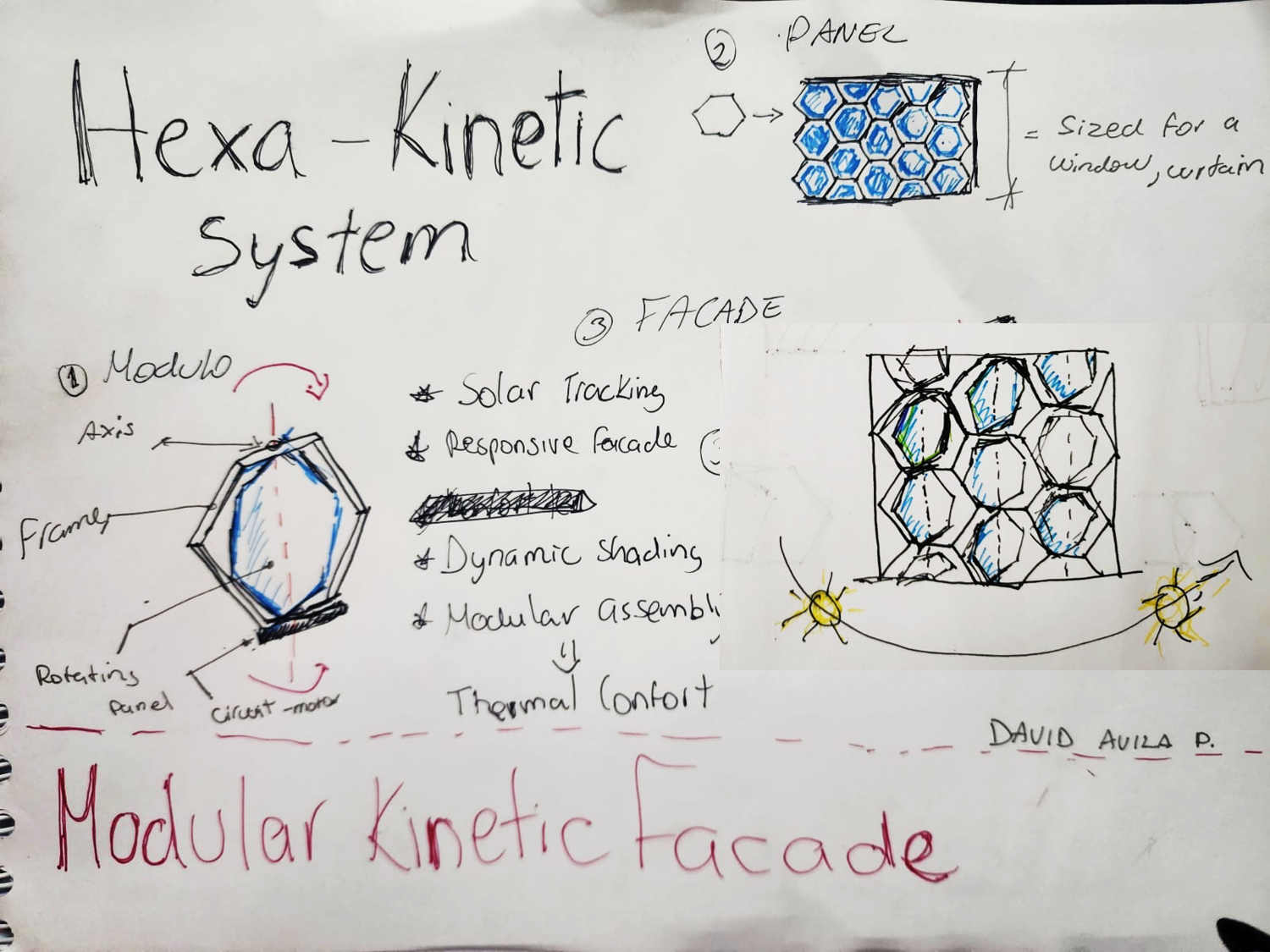
The HEXAMODULAR system is conceived as a responsive architectural skin composed of independent hexagonal modules that can be connected to create panels of different sizes and configurations. The hexagonal geometry allows the units to repeat efficiently, share their edges, and generate continuous patterns suitable for facades, windows, or shading installations.
The concept combines modularity, environmental responsiveness, and distributed control. Through ESP-NOW communication and the web interface, the modules can operate individually or coordinate movements such as opening, closing, and wave patterns. This makes HEXAMODULAR a scalable system in which digital fabrication, embedded electronics, and kinetic design work together to improve solar control while giving the architectural envelope an expressive and constantly changing appearance.
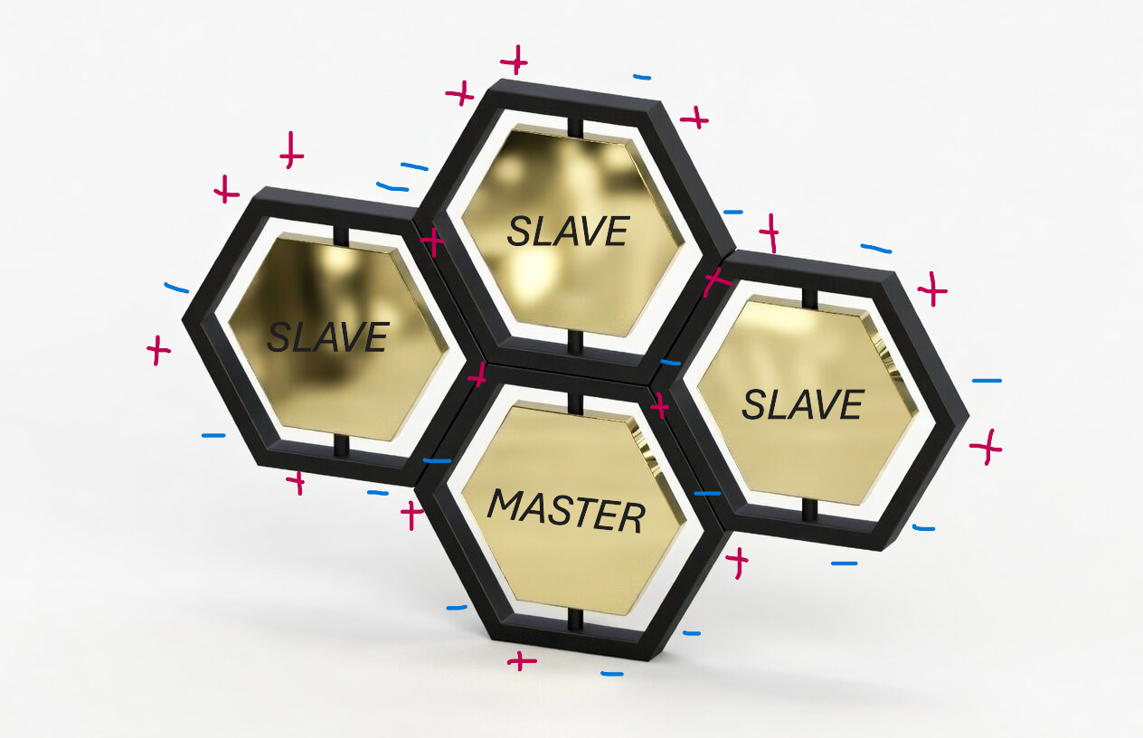
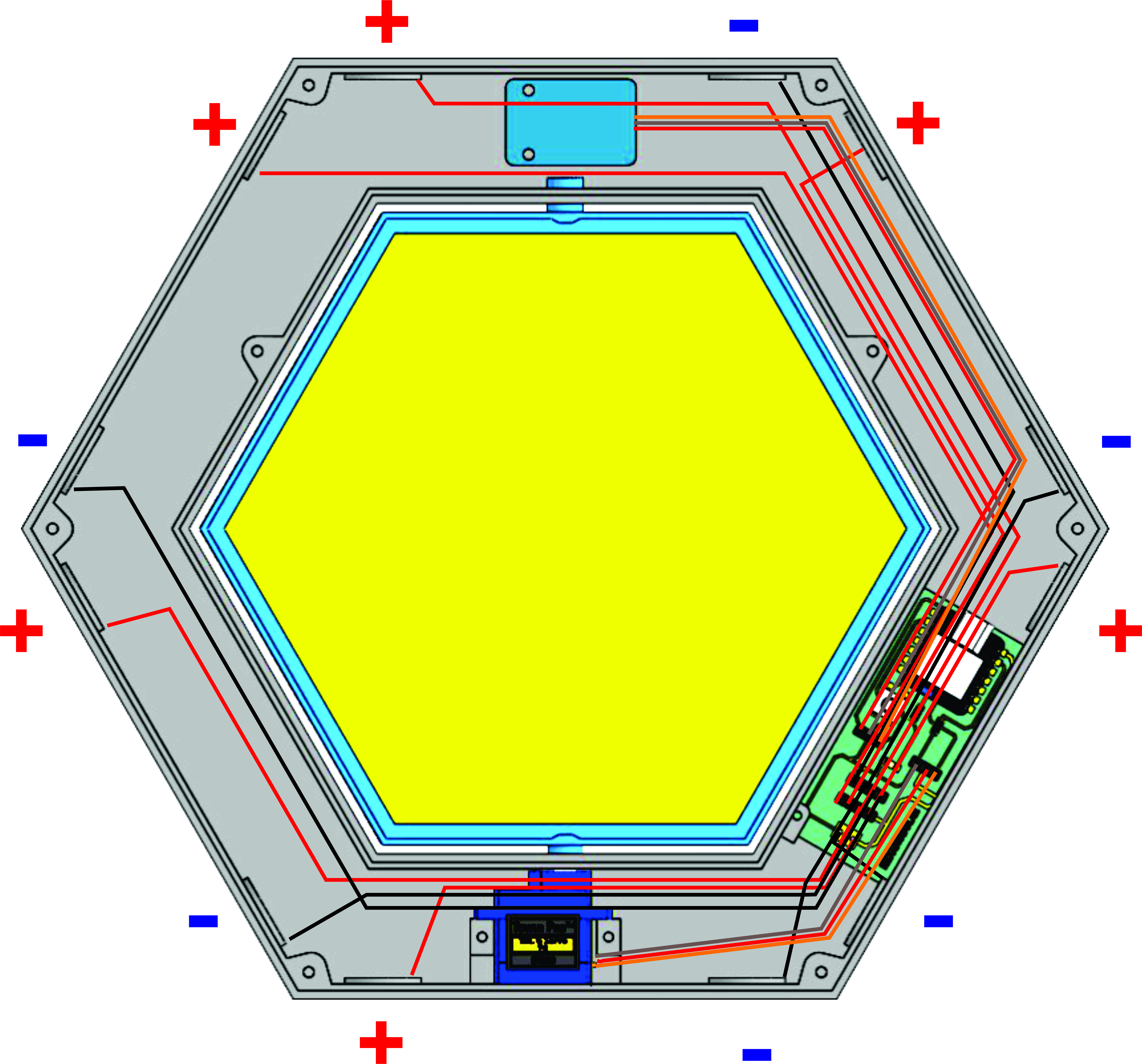
The image illustrates how several HEXAMODULAR units can be assembled as a single panel through the positive and negative connection poles distributed around each chassis. These poles use neodymium magnets as both mechanical connectors and electrical contacts: magnetic attraction aligns and holds neighboring modules together, while the conductive contact between the magnets transmits electrical power from one hexagon to the next. Their alternating polarity preserves the correct positive and negative connections throughout the panel. One module operates as the master, coordinating commands and communication, while the remaining slave modules reproduce the requested movements. This configuration simplifies assembly, testing, maintenance, and future expansion because individual modules can be connected, removed, or replaced without redesigning the complete panel.
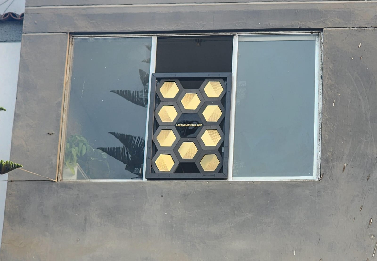
The complete HEXAMODULAR panel is contained within a structural perimeter frame that organizes, supports, and protects the connected modules as a single architectural element. For this prototype, the frame was conceived specifically for installation in a residential window, allowing the kinetic panel to operate as an adaptive shading device between the exterior environment and the interior space. The frame maintains the position of the modules, facilitates mounting on the existing opening, and enables the system to regulate direct sunlight while preserving its modular and removable construction.
PROCESS
DESIGN AND FABRICATION DEVELOPMENT
Computer-Aided Design
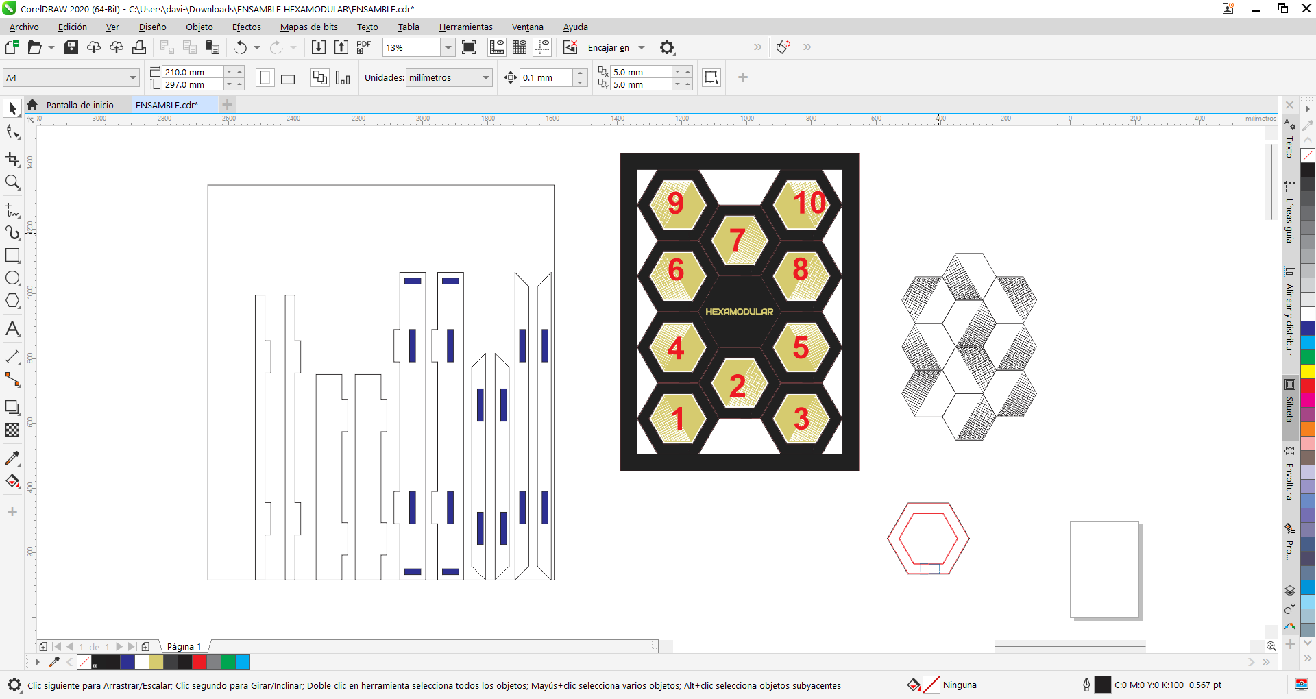
The knowledge gained in WEEK02 was used to develop a scalable model. Parametric design in Solidworks was used to build the chassis and create a 3D integration assembly of all mechanical and electronic components. 2D design was also used as a base in Corel Draw to define the panel frame and modular blades.
Computer-Controlled Cutting / Machining
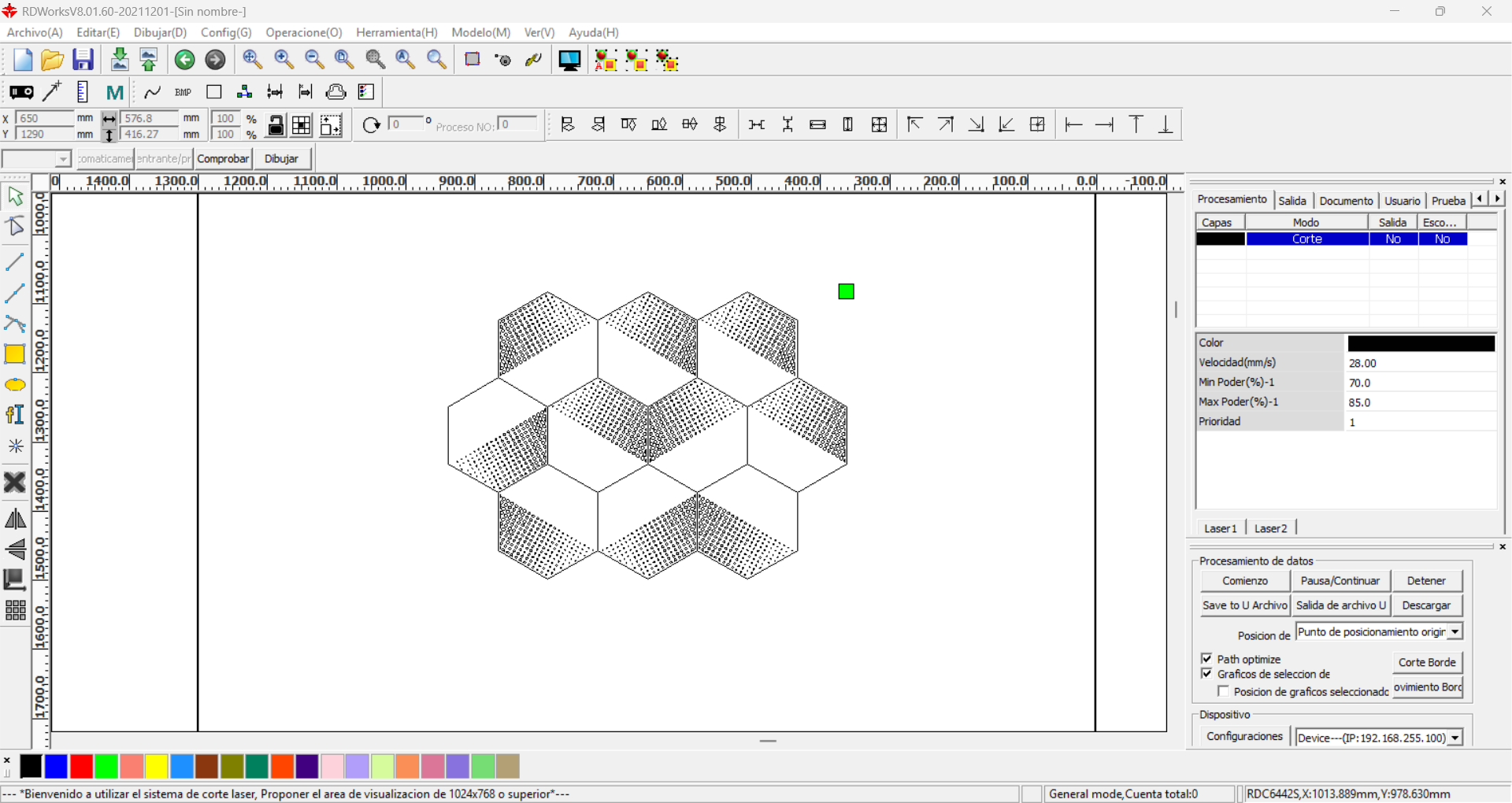
For the fabrication of some secondary components, laser cutting was required for the reflective golden blades, optimizing both material use and cutting time based on WEEK03 experience. The same laser machine was used with RDWorks, with the following parameters for cutting 2 mm acrylic: Speed 28 mm/s, Power 85%.
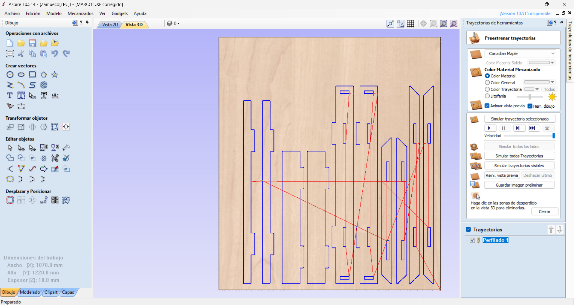
WEEK07 knowledge was also applied to machine the 18 mm MDF assembly frame using a CNC router. The toolpaths were prepared in Aspire with the following parameters: RPM 16000, feed rate 2500 mm/min, depth per pass 7 mm, using a 6 mm compression bit.
3D Printing
3D printing was used to fabricate the module chassis, following the WEEK05 workflow, using matte gray PLA filament. One challenge was that on one printer the chassis could not fit in a horizontal orientation, so it had to be printed vertically. On the Creality K2, printing time was reduced, with an approximate print time of 6 hours per modular chassis at a 0.2 mm layer height.
Electronics Design
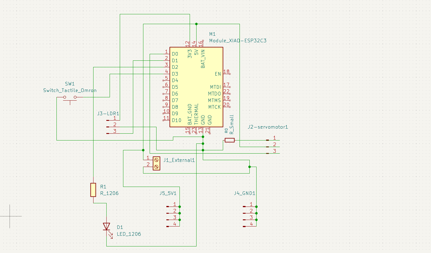
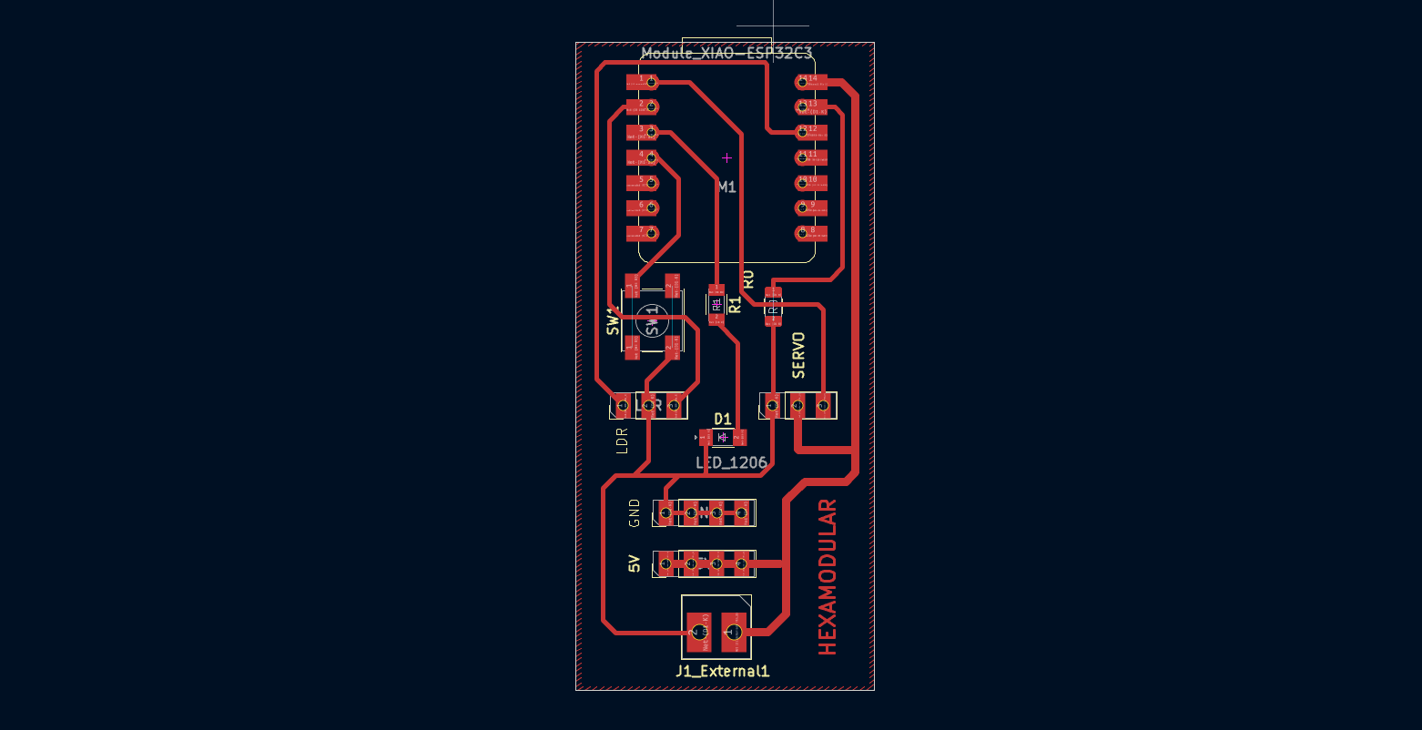
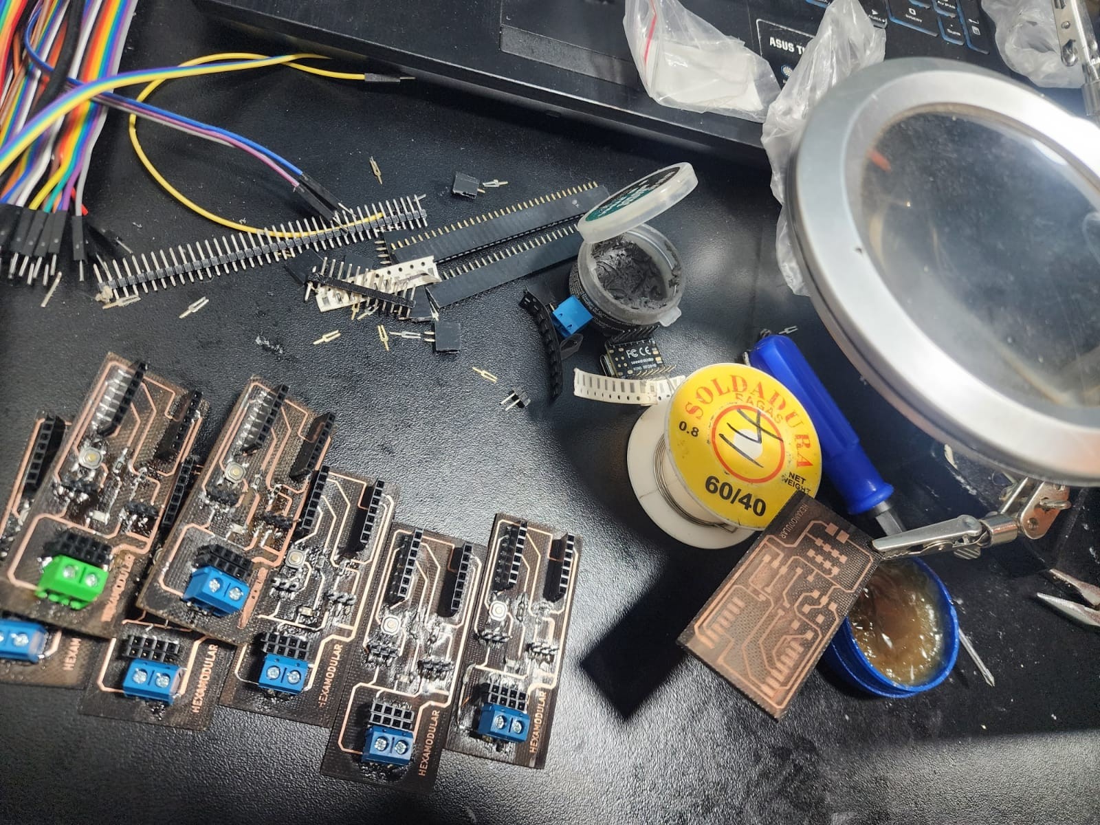
The electronic board design was developed starting in WEEK06 using KiCad. The layout was adapted to be as compact as possible while respecting trace spacing, resulting in an approximate board size of 29 mm x 66 mm. The final manufacturing files were then generated.
Electronics Production
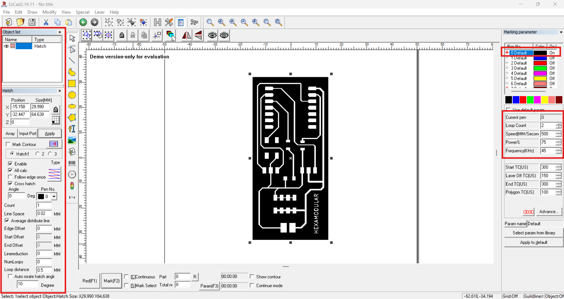
The electronic boards were fabricated using the process learned in WEEK08, specifically fiber laser engraving. EzCad was used with the same engraving parameters: speed 500 mm/s, power 70%, and frequency 45 kHz over 2 passes.
Input and Output devices
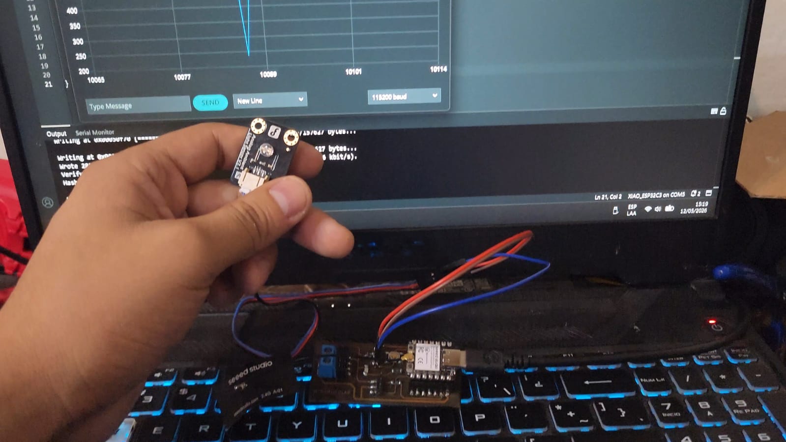
Input and output device installation and testing were performed first, using the light sensor and servo motor. A test code was developed to validate operation: the light sensor measures light intensity, and the servo rotates according to that intensity. WEEK09 and WEEK10.
#include <ESP32Servo.h>

const int PIN_SERVO = D0;
const int PIN_LIGHT = D1;

Servo myServo;

void setup() {
    Serial.begin(115200);

    myServo.attach(PIN_SERVO);
    pinMode(PIN_LIGHT, INPUT);
}

void loop() {

    int light = analogRead(PIN_LIGHT);

    // Map 4095 -> 0 deg and 2400 -> 90 deg
    int angle = map(light, 4095, 2400, 0, 90);

    // Limit range
    angle = constrain(angle, 0, 90);

    // Round to 10 deg steps
    angle = ((angle + 5) / 10) * 10;

    myServo.write(angle);

    Serial.print("Light: ");
    Serial.print(light);
    Serial.print("  ->  Angle: ");
    Serial.println(angle);

    delay(100);
}
Programming and interface
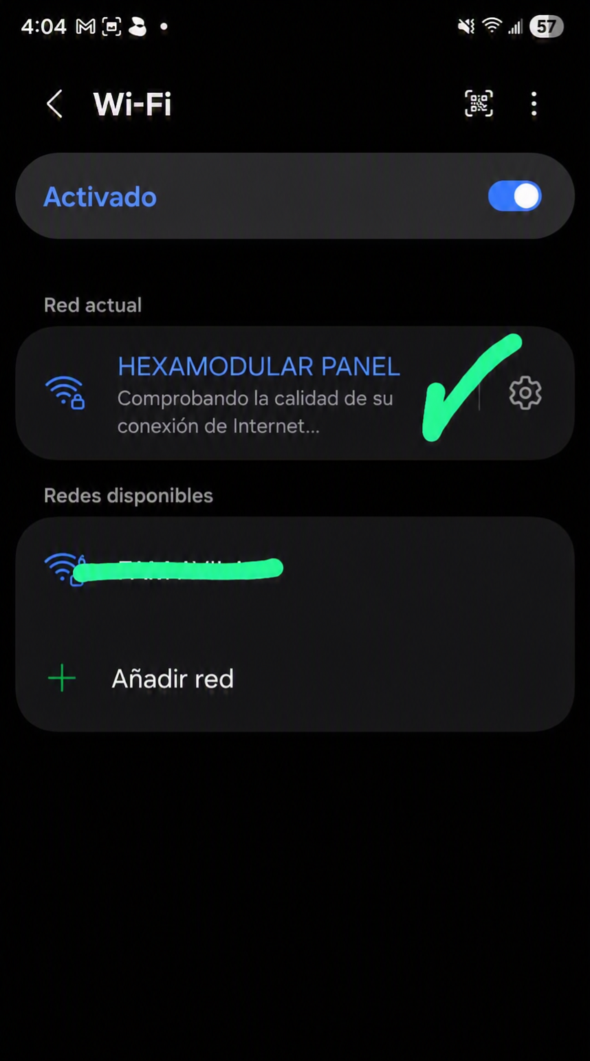
A remote interface was developed to control the system using Wi-Fi communication and a web server integrated into the master module. The interface has 5 action buttons: the first opens the panel, the second closes the panel, the third activates a left-to-right wave mode, the fourth activates a right-to-left wave mode, and the fifth toggles the light sensor on or off. WEEK11
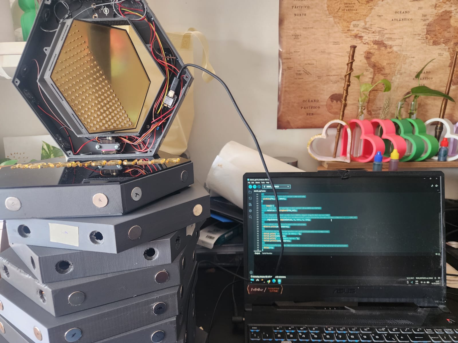
The code used for system programming was developed in the Arduino IDE environment, using the required libraries for Wi-Fi communication, servo control, and light sensor handling. The master code receives light sensor signals and sends commands to the slave modules so they can perform the corresponding movement. For this, the MAC address of each slave module was required. WEEK04
MASTER CODE
#include <WiFi.h>
#include <WebServer.h>
#include <esp_now.h>
#include <ESP32Servo.h>

#define PIN_SERVO D0
#define PIN_SENSOR D1

bool sensorEnabled = false;
int lastAngle = -1;

Servo myServo;
WebServer server(80);

typedef struct {
    int angle;
} ServoData;

ServoData dataToSend;

// MAC addresses of slave modules
uint8_t HEX1[]  = {0xE8, 0xF6, 0x0A, 0x13, 0xFC, 0x64};
uint8_t HEX3[]  = {0x80, 0xF1, 0xB2, 0x60, 0x2B, 0xE8};
uint8_t HEX4[]  = {0x1C, 0xDB, 0xD4, 0xEC, 0xFB, 0x8C};
uint8_t HEX5[]  = {0x1C, 0xDB, 0xD4, 0xEA, 0xBF, 0x74};
uint8_t HEX6[]  = {0xE8, 0xF6, 0x0A, 0x14, 0x9F, 0x10};
uint8_t HEX7[]  = {0x80, 0xF1, 0xB2, 0x60, 0x67, 0x68};
uint8_t HEX8[]  = {0x1C, 0xDB, 0xD4, 0xEA, 0xC3, 0x08};
uint8_t HEX9[]  = {0x1C, 0xDB, 0xD4, 0xEA, 0xC0, 0xBC};
uint8_t HEX10[] = {0x80, 0xF1, 0xB2, 0x60, 0x44, 0x60};

uint8_t* peers[] = {
  HEX1, HEX3, HEX4, HEX5, HEX6, HEX7, HEX8, HEX9, HEX10
};

const int NUM_PEERS = sizeof(peers) / sizeof(peers[0]);

void addPeer(uint8_t *mac) {
  esp_now_peer_info_t peerInfo = {};
  memcpy(peerInfo.peer_addr, mac, 6);
  peerInfo.channel = 1;
  peerInfo.encrypt = false;
  if (esp_now_add_peer(&peerInfo) == ESP_OK) {
        Serial.println("Peer added");
  } else {
        Serial.println("Error adding peer");
  }
}

void sendToPeer(uint8_t *mac, int angle) {
    dataToSend.angle = angle;
    esp_now_send(mac, (uint8_t *)&dataToSend, sizeof(dataToSend));
}

void sendToAll(int angle) {
    myServo.write(angle);
    dataToSend.angle = angle;
  for (int i = 0; i < NUM_PEERS; i++) {
        esp_now_send(peers[i], (uint8_t *)&dataToSend, sizeof(dataToSend));
  }
    Serial.print("Sent angle: ");
    Serial.println(angle);
}

void openAll() {
    sendToAll(90);
  server.sendHeader("Location", "/");
  server.send(303);
}

void closeAll() {
    sendToAll(0);
  server.sendHeader("Location", "/");
  server.send(303);
}

void waveRightToLeft() {
    int waitTime = 150;
    sendToPeer(HEX10, 90); delay(waitTime); sendToPeer(HEX10, 0);
    sendToPeer(HEX9, 90); delay(waitTime); sendToPeer(HEX9, 0);
    sendToPeer(HEX8, 90); delay(waitTime); sendToPeer(HEX8, 0);
    sendToPeer(HEX7, 90); delay(waitTime); sendToPeer(HEX7, 0);
    sendToPeer(HEX6, 90); delay(waitTime); sendToPeer(HEX6, 0);
    sendToPeer(HEX5, 90); delay(waitTime); sendToPeer(HEX5, 0);
    sendToPeer(HEX4, 90); delay(waitTime); sendToPeer(HEX4, 0);
    sendToPeer(HEX3, 90); delay(waitTime); sendToPeer(HEX3, 0);
    myServo.write(90); delay(waitTime); myServo.write(0);
    sendToPeer(HEX1, 90); delay(waitTime); sendToPeer(HEX1, 0);
}

void startWaveRightToLeft() {
    waveRightToLeft();
  server.sendHeader("Location", "/");
  server.send(303);
}

void waveLeftToRight() {
    int waitTime = 150;
    sendToPeer(HEX1, 90); delay(waitTime); sendToPeer(HEX1, 0);
    myServo.write(90); delay(waitTime); myServo.write(0);
    sendToPeer(HEX3, 90); delay(waitTime); sendToPeer(HEX3, 0);
    sendToPeer(HEX4, 90); delay(waitTime); sendToPeer(HEX4, 0);
    sendToPeer(HEX5, 90); delay(waitTime); sendToPeer(HEX5, 0);
    sendToPeer(HEX6, 90); delay(waitTime); sendToPeer(HEX6, 0);
    sendToPeer(HEX7, 90); delay(waitTime); sendToPeer(HEX7, 0);
    sendToPeer(HEX8, 90); delay(waitTime); sendToPeer(HEX8, 0);
    sendToPeer(HEX9, 90); delay(waitTime); sendToPeer(HEX9, 0);
    sendToPeer(HEX10, 90); delay(waitTime); sendToPeer(HEX10, 0);
}

void startWave() {
    waveLeftToRight();
  server.sendHeader("Location", "/");
  server.send(303);
}

void toggleSensor() {
    sensorEnabled = !sensorEnabled;
  server.sendHeader("Location", "/");
  server.send(303);
}

void mainPage() {
  String html = "<html><head>";
  html += "<meta name='viewport' content='width=device-width, initial-scale=1'>";
  html += "</head><body><h1>HEXAMODULAR</h1>";
    html += "<p><a href='/open'><button style='width:250px;height:80px;font-size:24px'>";
    html += "OPEN ALL</button></a></p>";
    html += "<p><a href='/close'><button style='width:250px;height:80px;font-size:24px'>";
    html += "CLOSE ALL</button></a></p>";
    html += "<p><a href='/wave'><button style='width:250px;height:80px;font-size:24px'>";
    html += "WAVE LEFT -> RIGHT</button></a></p>";
    html += "<p><a href='/wave2'><button style='width:250px;height:80px;font-size:24px'>";
    html += "WAVE RIGHT -> LEFT</button></a></p>";
  html += "<p><a href='/sensor'><button style='width:250px;height:80px;font-size:24px'>";
    html += (sensorEnabled ? "SENSOR: ON" : "SENSOR: OFF");
  html += "</button></a></p></body></html>";
  server.send(200, "text/html", html);
}

void setup() {
  Serial.begin(115200);
    myServo.attach(PIN_SERVO);
  pinMode(PIN_SENSOR, INPUT);
  WiFi.mode(WIFI_AP_STA);
  WiFi.softAP("HexaPanel", "12345678", 1);
  Serial.println();
  Serial.print("IP: ");
  Serial.println(WiFi.softAPIP());
  if (esp_now_init() != ESP_OK) {
    Serial.println("Error ESP-NOW");
    while (true) delay(1000);
  }
  for (int i = 0; i < NUM_PEERS; i++) {
        addPeer(peers[i]);
  }
    server.on("/", mainPage);
    server.on("/open", openAll);
    server.on("/close", closeAll);
    server.on("/wave", startWave);
    server.on("/wave2", startWaveRightToLeft);
    server.on("/sensor", toggleSensor);
  server.begin();
    Serial.println("Server started");
}

void loop() {
  server.handleClient();
    if(sensorEnabled) {
        int light = analogRead(PIN_SENSOR);
        int angle = map(light, 4095, 1800, 0, 90);
        angle = ((angle + 5) / 10) * 10;
        angle = constrain(angle, 0, 90);
        if(angle != lastAngle) {
            sendToAll(angle);
            Serial.print("Light: ");
            Serial.print(light);
            Serial.print("  Angle: ");
            Serial.println(angle);
            lastAngle = angle;
    }
  }
  delay(100);
}
SLAVE CODE
#include <WiFi.h>
#include <esp_now.h>
#include <ESP32Servo.h>

#define PIN_SERVO D0

Servo myServo;

typedef struct {
    int angle;
} ServoData;

ServoData receivedData;

void OnDataRecv(const esp_now_recv_info_t *info,
                const uint8_t *incomingData,
                int len) {
    memcpy(&receivedData, incomingData, sizeof(receivedData));
    myServo.write(receivedData.angle);
    Serial.print("Received angle: ");
    Serial.println(receivedData.angle);
}

void setup() {
  Serial.begin(115200);
    myServo.attach(PIN_SERVO);
  WiFi.mode(WIFI_STA);

  if (esp_now_init() != ESP_OK) {
    Serial.println("Error ESP-NOW");
    return;
  }

  esp_now_register_recv_cb(OnDataRecv);
    Serial.println("SLAVE READY");
}

void loop() {
}
System integration
System integration was carried out by combining all mechanical, electronic, and software components into one complete functional module. Each part was validated individually before being integrated into the full HEXAMODULAR unit, ensuring proper fit, electrical continuity, and responsive behavior under different lighting conditions. The complete chassis was also integrated and the corresponding tests were performed. WEEK16
FINAL RESULT
HEXAMODULAR KINETIC SYSTEM COMPLETE
An initial final result was achieved with one base module and one slave module. The base module receives the light sensor signal and sends commands to the slave modules so they can perform the corresponding movement. Tests were performed under direct sunlight and indoor shadow conditions in the house.
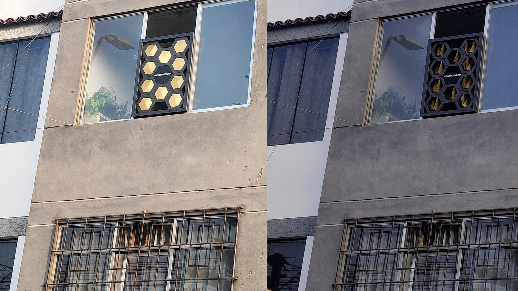
The first full assembly of the HEXAMODULAR system was completed by integrating all modules and verifying their combined operation. Opening and closing tests were performed, along with wave mode activation and light sensor response. The system proved to be functional and capable of adapting to lighting conditions, providing dynamic control over solar radiation on the facade.
As a final step, the system was installed in the real setting of a residential window. The installation was straightforward; the panel is lightweight and easy to mount. Functional tests were carried out at different times of day, verifying the system response to direct sunlight and shade, as well as mobile phone control.