WEEK 16
System Integration
- Design and document the system integration for your final project.
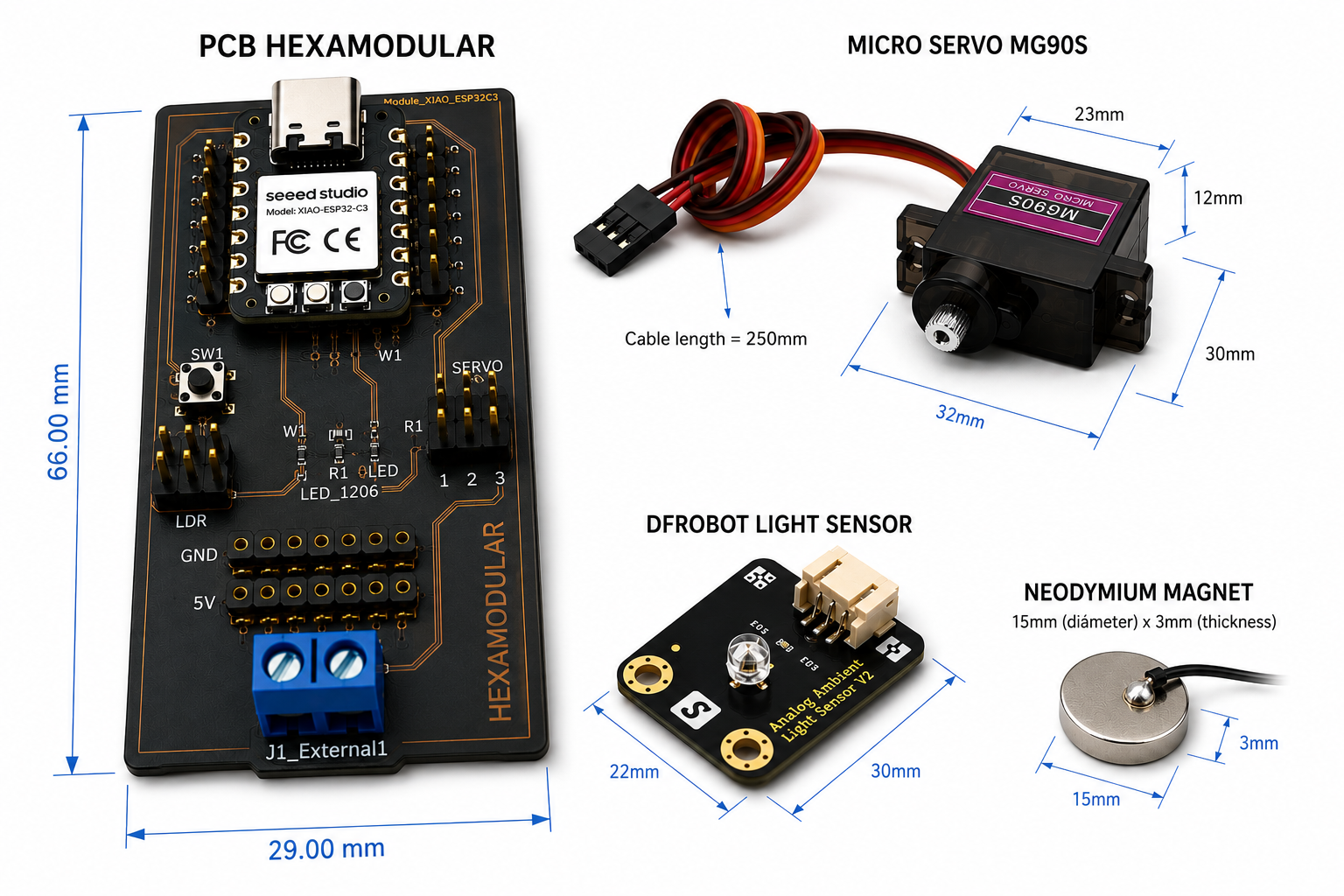
Integrated electronic components
Chassis Design
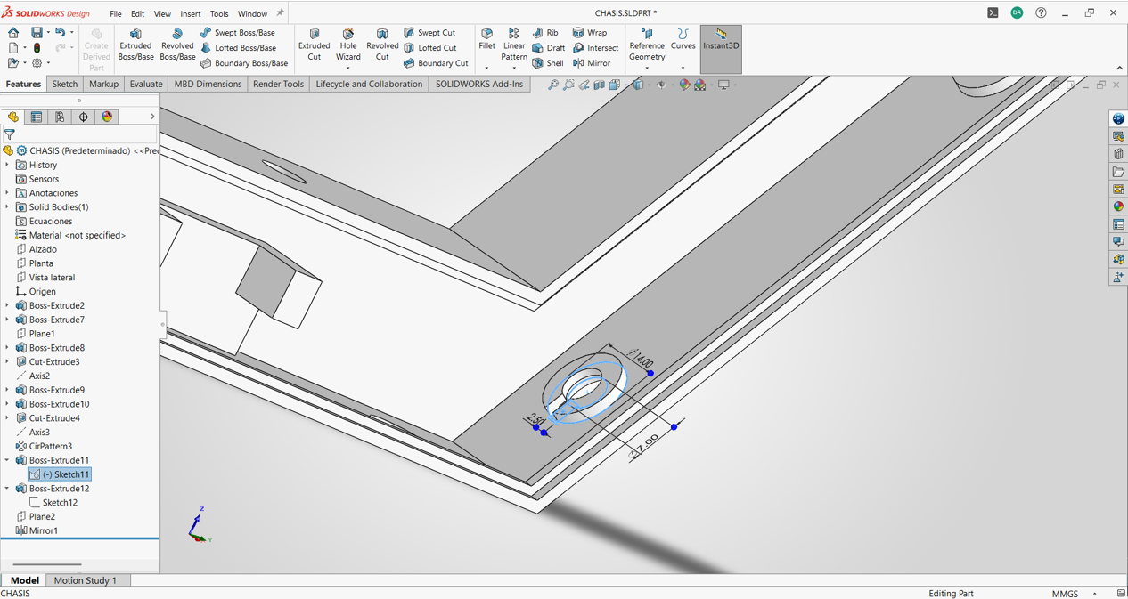
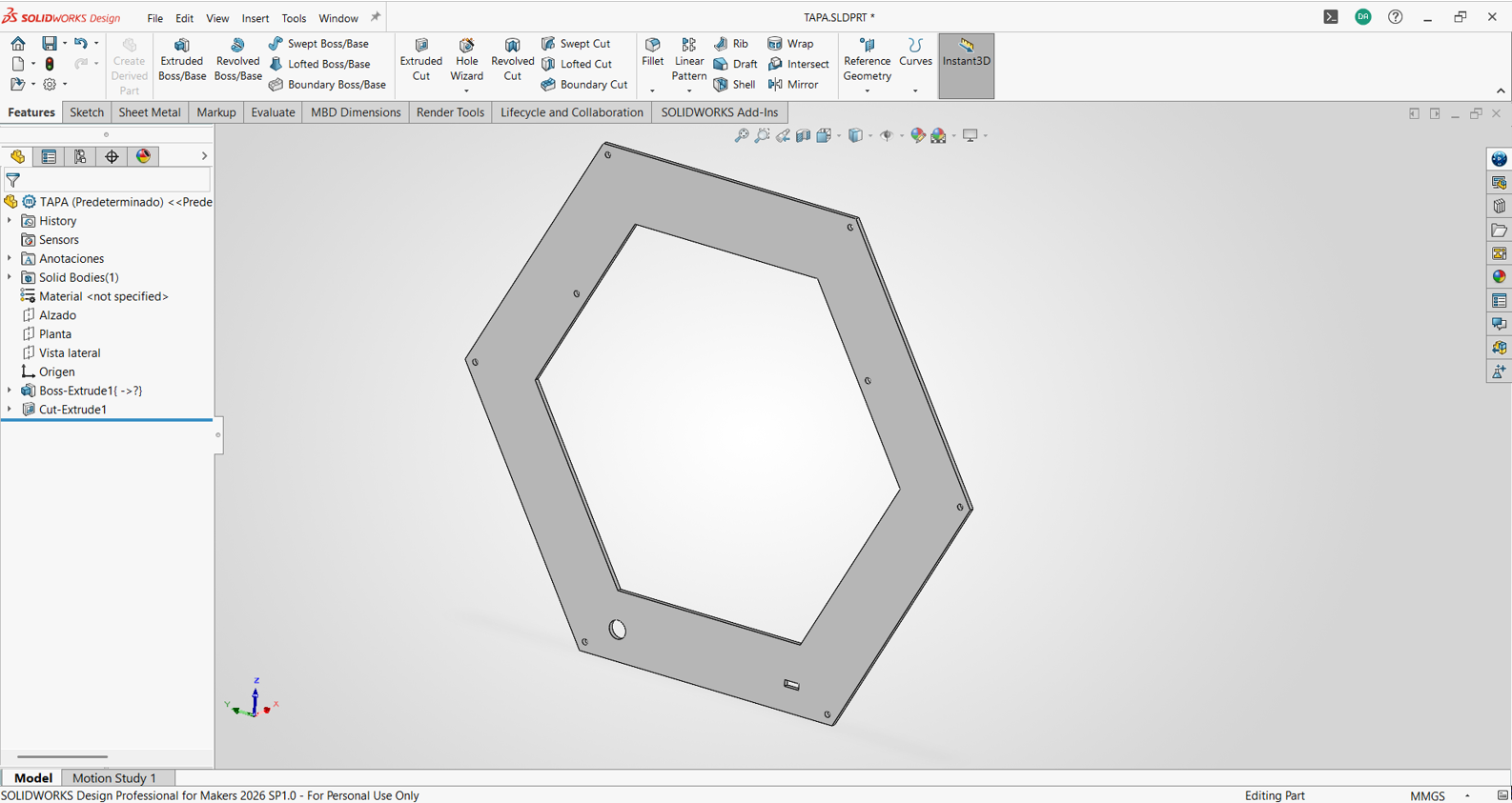
Once the dimensions of the electronic components were defined, I designed the chassis to house each of them. I emphasized the PCB dimensions so the chassis would not be overly robust and would instead adapt to each component's needs. In this case, the chassis was given a 2 mm thickness for good support. For this, I used SolidWorks design software, with which I created a modular design to facilitate integration and future system maintenance.
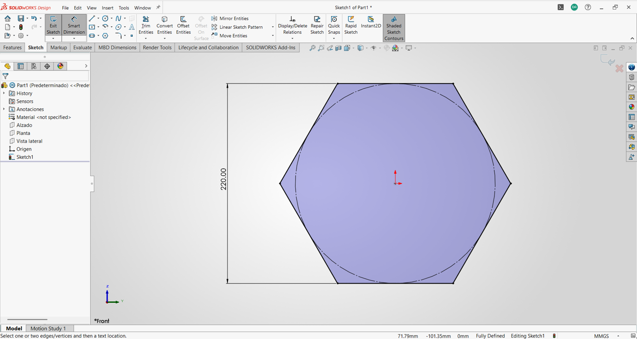
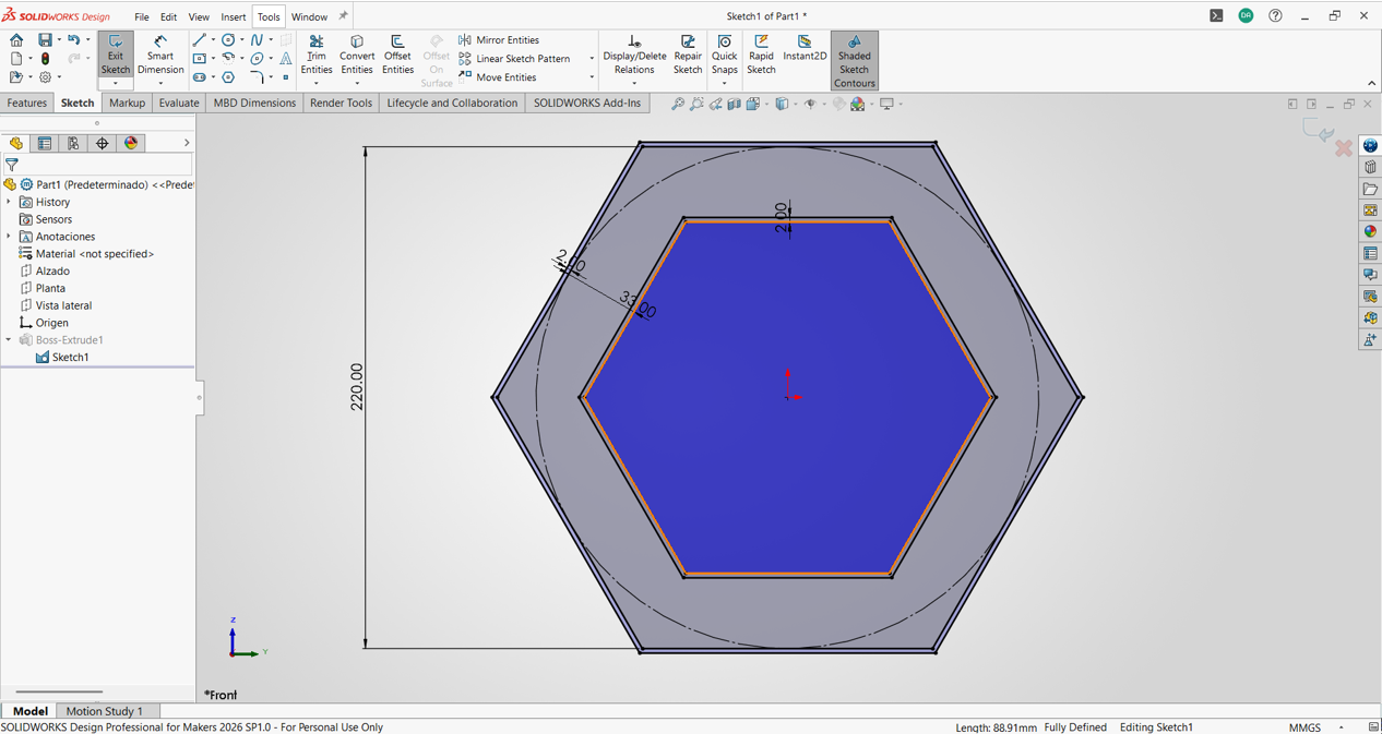
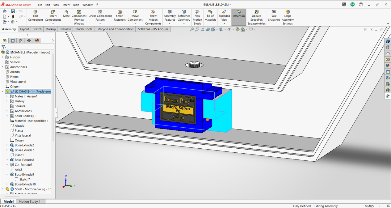
Then, I designed the mount for the micro servo considering its dimensions and fixing points. It has a hole for integrating the micro servo shaft and the rotating hexagonal plate.
I also designed the mount for the light sensor, considering its fixing points and sensor diameter. It includes a hole for sensor integration and attachment to the chassis.
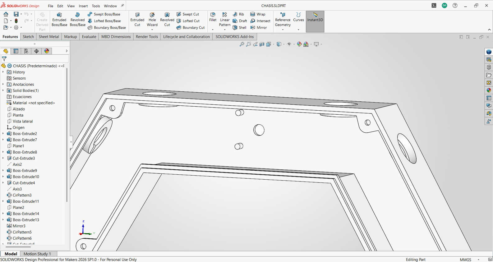
For the magnets, design and fastening tests were carried out. The design was defined by the magnet diameter, and a clearance was added based on thickness to leave space for silicone adhesive and seal the magnet connection.
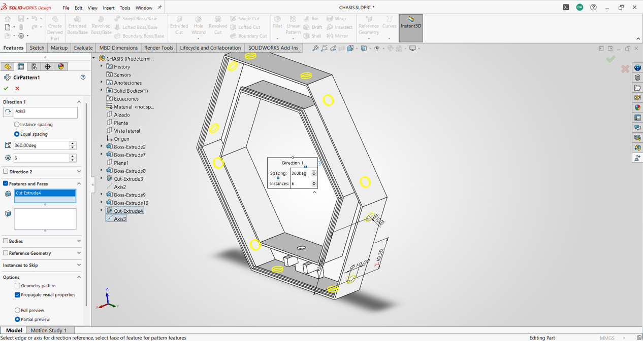
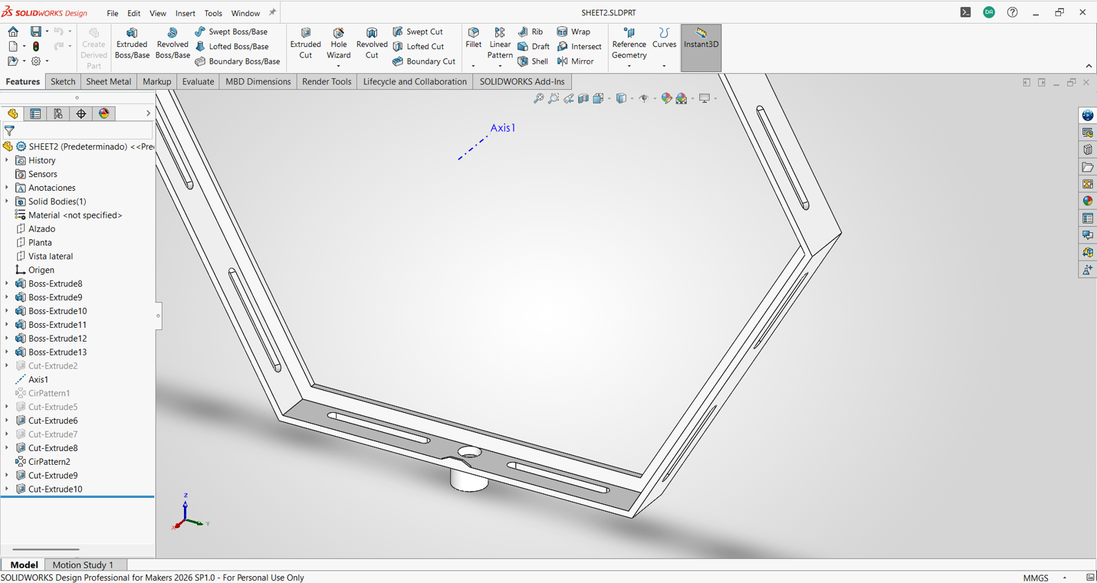
Rotating Frame and Rear Cover Design
I designed the rotating frame that is driven by the micro servo and fixed through a pin. This rotating frame has slots to mount an acrylic and polycarbonate sheet, creating a thermal-insulation concept.
I also designed the rear cover of the chassis, which is fixed with screws. This cover has a hole for integrating the charging connector and a USB Type-C port for programming, but only for the MOTHER HEXAGON; the other hexagons do not include this.
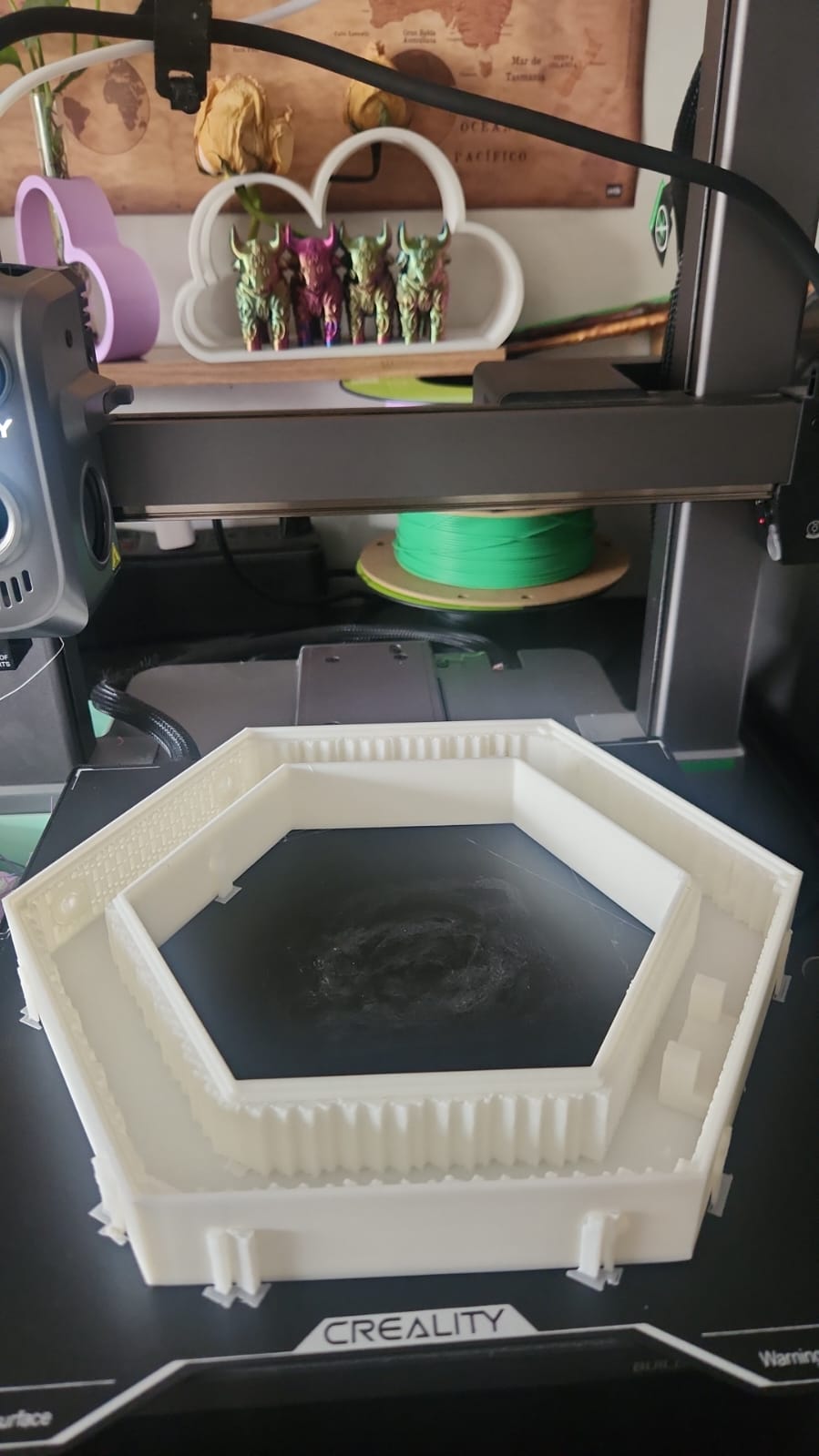
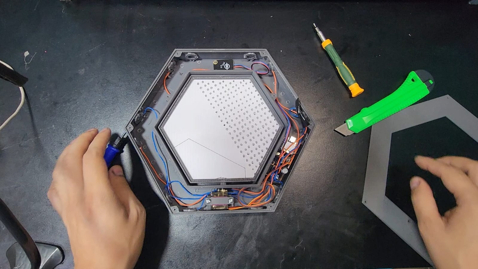
Test Fabrication
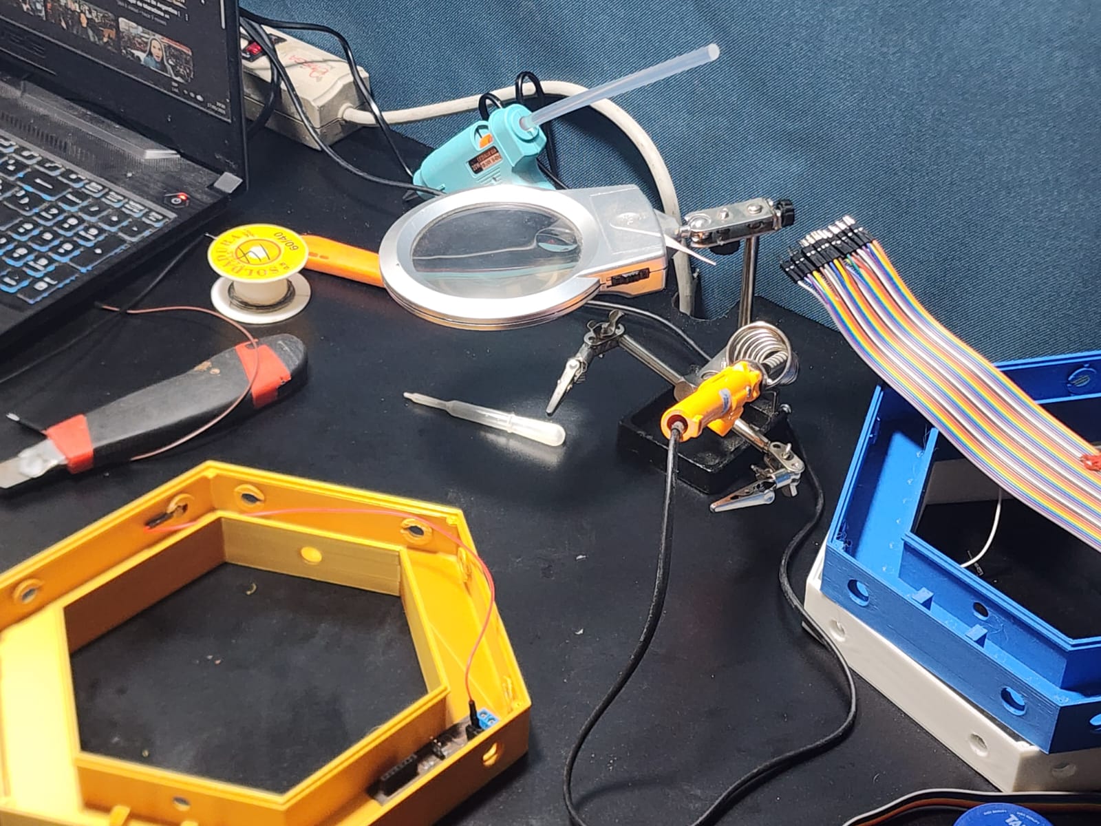
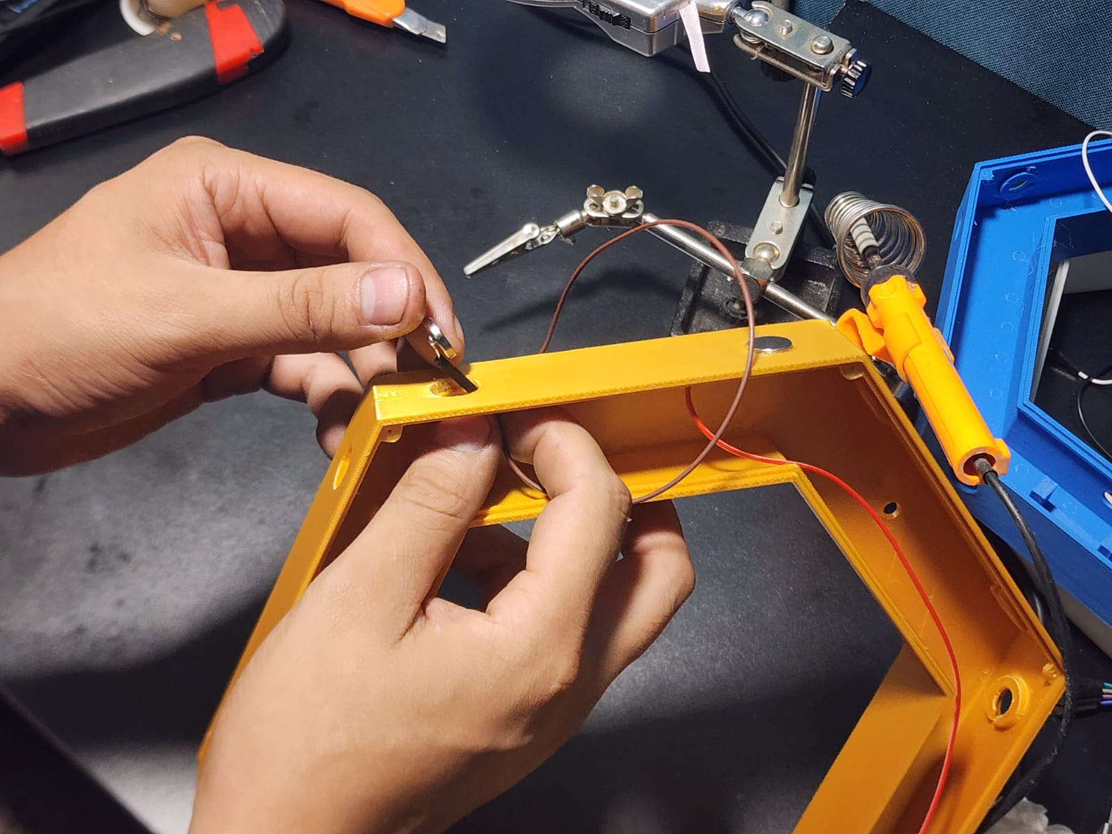
I fabricated and validated key parts required for integration, then tested tolerances and fit before final assembly. These checks helped reduce mechanical stress, improve cable routing, and make the complete setup more reliable.
Finally, I uploaded the integrated and performed full-system validation tests. The result was a functional prototype where electronics, mechanics, and control logic operate together according to the final project requirements.
Prototype Results
Once the initial prototypes were printed, assembly tests were carried out to verify that each component fit correctly. Functional tests were also performed to confirm that each component worked properly and that there were no connection errors. This was done for a pair of hexagonal modules.
Magnet Strength
An initial test was performed with a smaller 12 mm diameter magnet, but the result was negative because it did not adhere strongly enough, which was necessary due to the weight of the full chassis.
The final magnet was 15 mm x 3 mm thick, and the result was positive because it adhered with strong force. A resistance test was also performed to verify that the magnet could support the full chassis weight and would not detach easily.
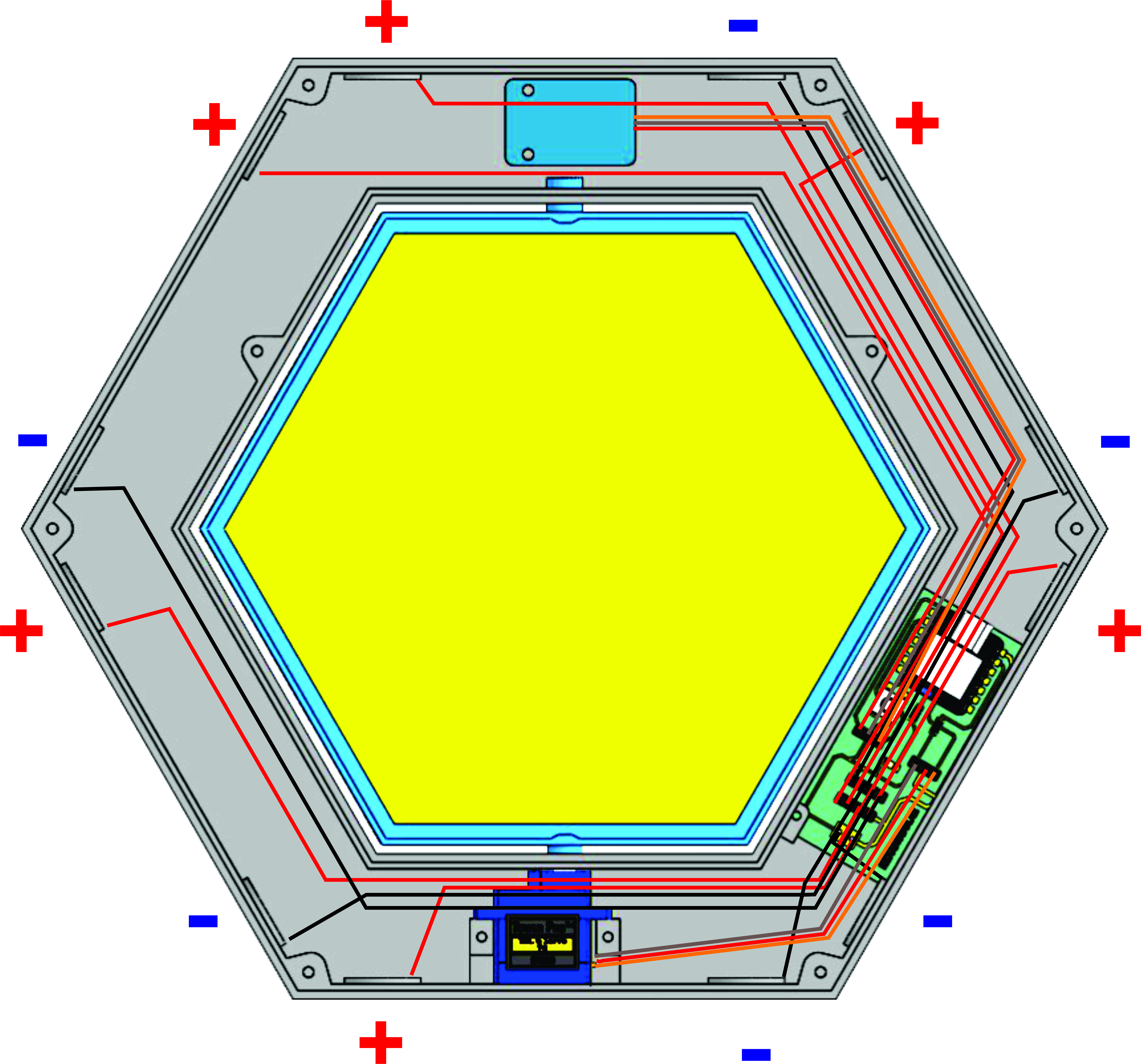
Connection Assembly A
Thanks to the 3D design, it is possible to create a wiring scheme for a hexagonal module. This helps organize the connections and define the assembly order, while also enabling connection tests to verify that each component is properly connected and that there are no connection errors.
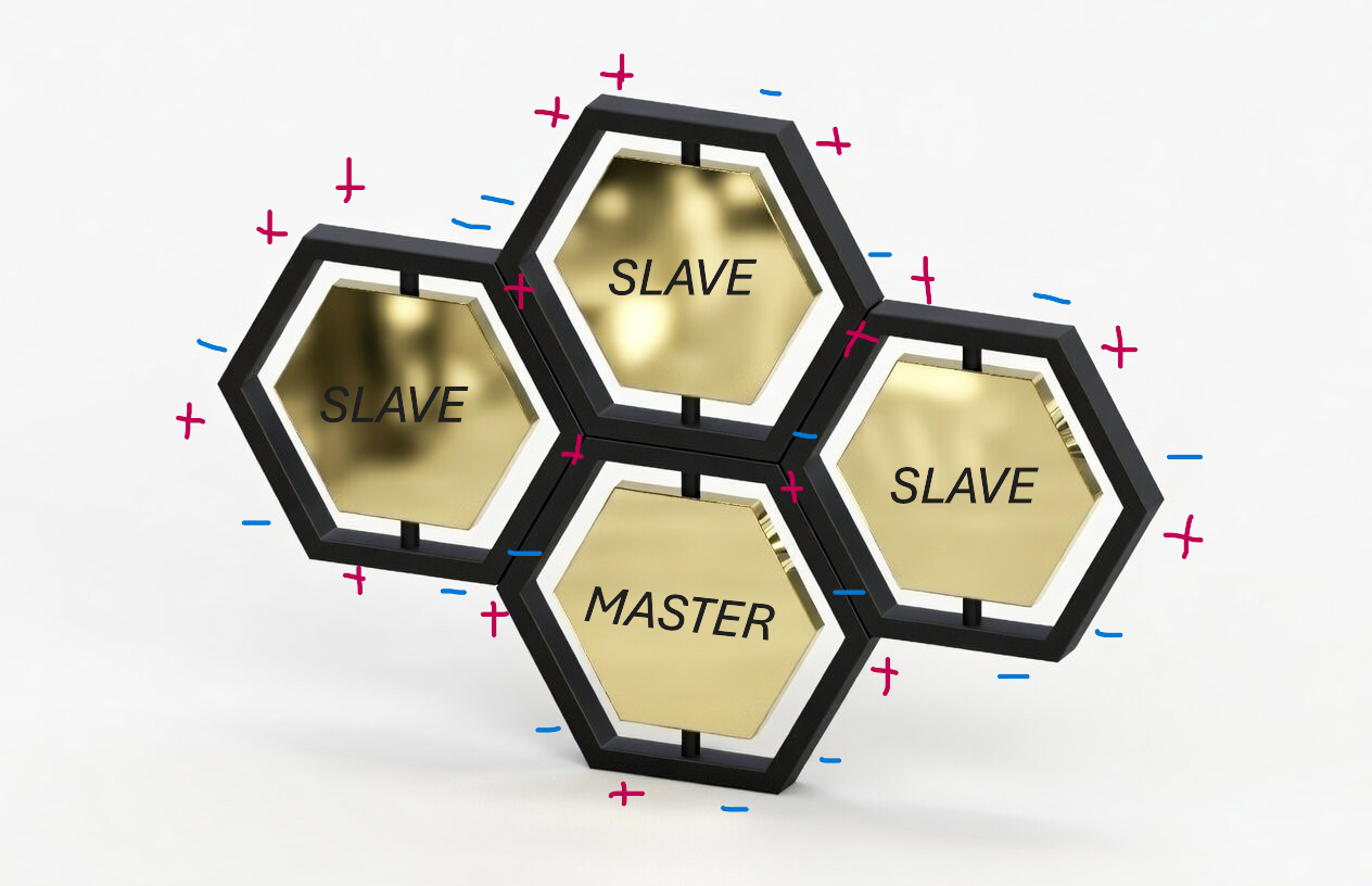
Connection Assembly B
Connection Assembly B is based on creating a panel with different hexagons, using the positive and negative poles of each chassis. A master-slave programming scheme is also used for communication between each hexagonal module. This facilitates connection and system maintenance, and allows connection tests to verify that each component is connected correctly and that there are no connection errors.
Final Integration
Progress was made with a first hexagonal module to integrate the electronic components. This was done to verify that each component was connected correctly and that there were no connection errors. The video shows the module with a first golden reflective plate for the rotating shaft. It also shows the press-fit cover, which can also be fixed with screws.
First Tests
The first tests were carried out with 2 modules to verify the electronic rotation mechanism. A first base code was generated for both modules independently. Under lamp light, servo movement can be observed. Although it was programmed to 90 degrees, the rotating frame still needs finer adjustment.
#include <ESP32Servo.h>

const int PIN_SERVO = D0;
const int PIN_LUZ   = D1;

Servo miServo;

void setup() {
    Serial.begin(115200);

    miServo.attach(PIN_SERVO);
    pinMode(PIN_LUZ, INPUT);
}

void loop() {

    int luz = analogRead(PIN_LUZ);

    // Map 4095 -> 0 deg and 2400 -> 90 deg
    int angulo = map(luz, 4095, 2400, 0, 90);

    // Limit range
    angulo = constrain(angulo, 0, 90);

    // Round to 10 deg steps
    angulo = ((angulo + 5) / 10) * 10;

    miServo.write(angulo);

    Serial.print("Luz: ");
    Serial.print(luz);
    Serial.print("  ->  Angle: ");
    Serial.println(angulo);

    delay(100);
}