WEEK 07
Computer-Controlled Machining
Group assignment:
- Complete your lab's safety training.
- Test runout, alignment, fixturing, speeds, feeds, materials and toolpaths for your machine.
- Document your work to the group work page and reflect on your individual page what you learned.
What I Learned From Teamwork
Safety training
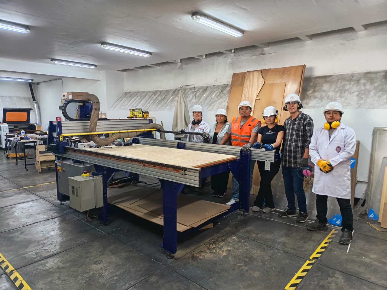
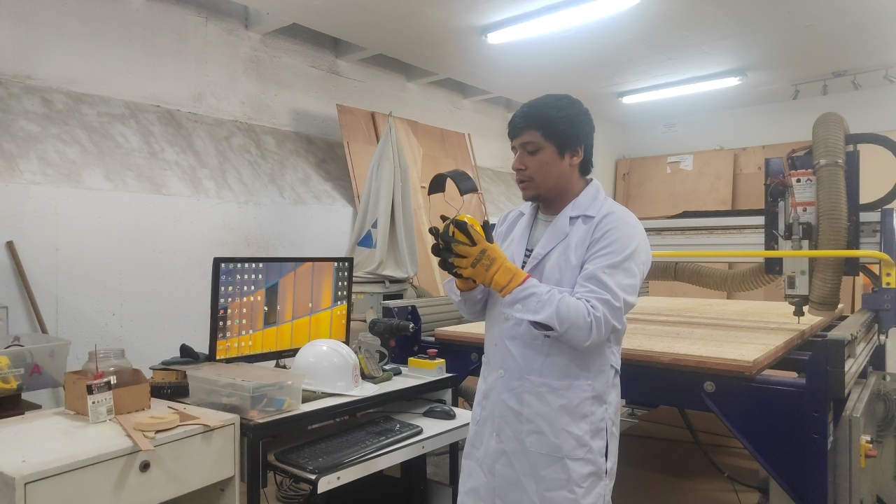
Before operating the machine, we received a safety briefing from Jefferson Lados Villegas, Operational Laboratory Equipment Specialist. During this induction, we reviewed the personal protective equipment required before handling the machine and the material, as well as the safety conditions of the workspace. The training included mandatory use of PPE, machine safety zones and floor markings, emergency stop procedures, machine startup system, safe interaction with the control software and physical controls, and keeping the work area clean and clear before operation. We were instructed to use proper clothing and protection, including gloves, safety glasses, hearing protection, helmet, and in some cases a lab coat or protective clothing, as well as closed shoes and appropriate long clothing. We also identified the machine’s emergency stop button, located next to the machine, and the startup key used to enable machine operation:


Safe workspace and protective measures
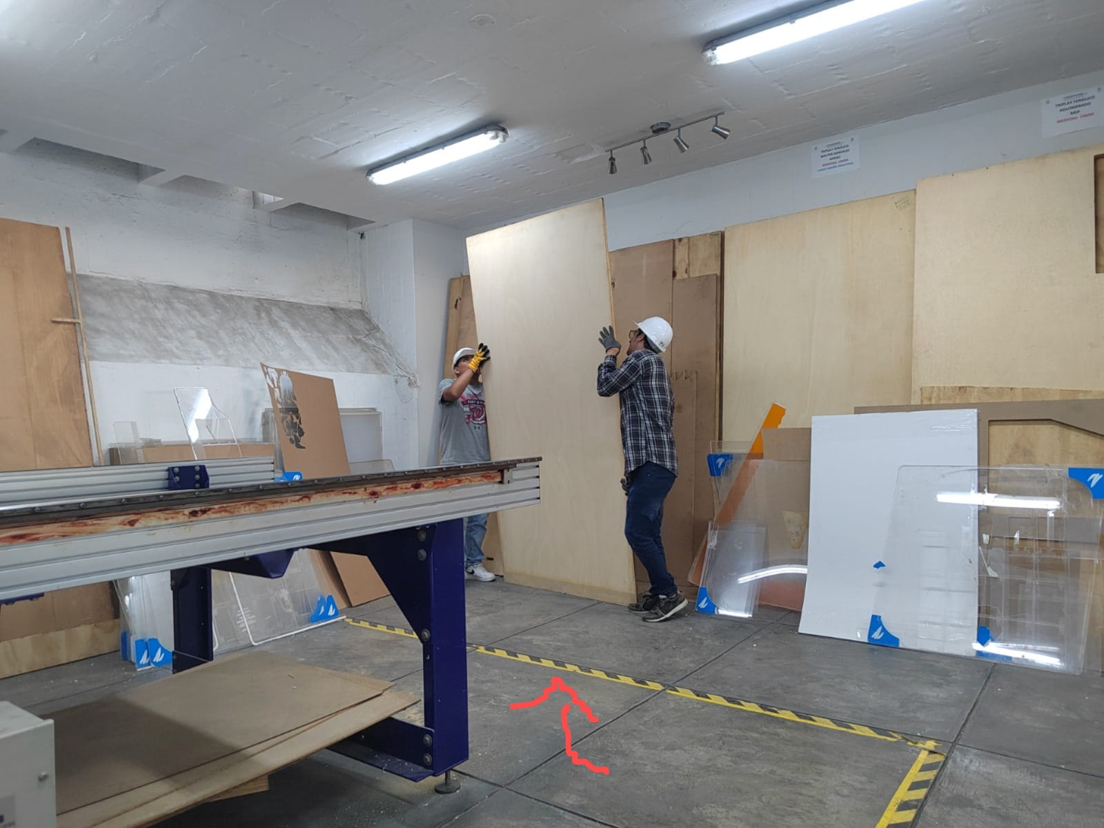
Before turning on the machine, we checked that the workspace was clear, the sacrificial bed was clean, there were no objects interfering with the machine path or operator movement, the safety area was clearly marked, the required PPE was being used, and a dry chemical fire extinguisher was available nearby. This step helped us understand that safe CNC machining depends not only on the machine itself, but also on preparation of the environment and operator awareness.
Press-fit tests
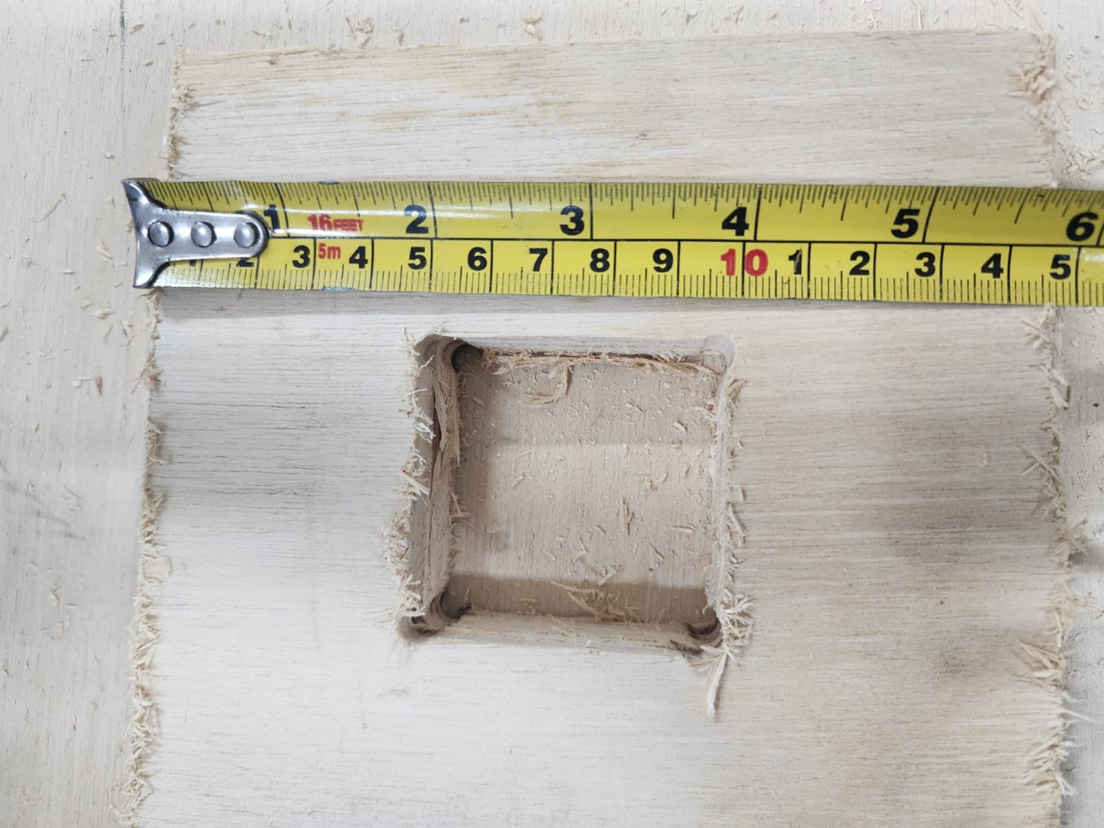
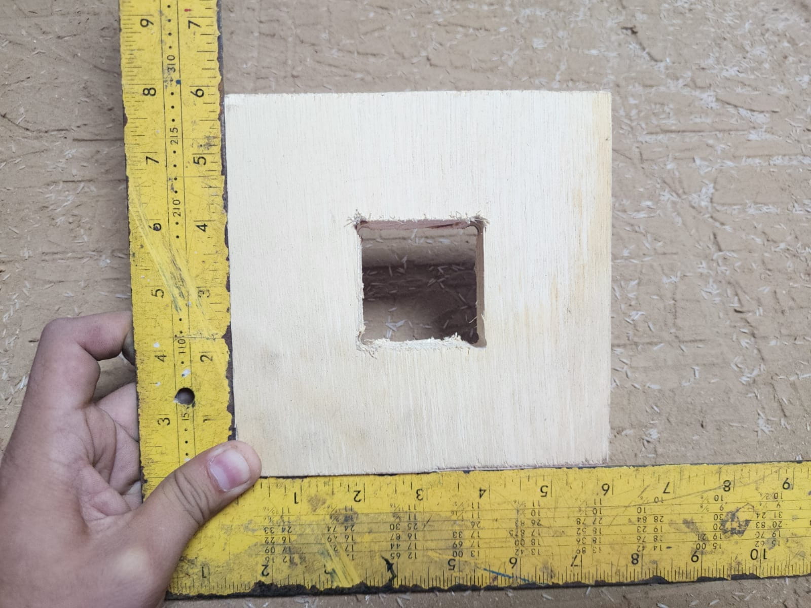
As part of our testing process, we fabricated a square test and a comb test to evaluate press-fit behavior, material tolerance, and joint adjustment. The square test had an outer size of 150 mm x 150 mm and an internal square cutout of 50 mm x 50 mm. The comb test had overall dimensions of 420 mm x 100 mm and included slots from 18.00 mm to 20.00 mm in increments of 0.25 mm.
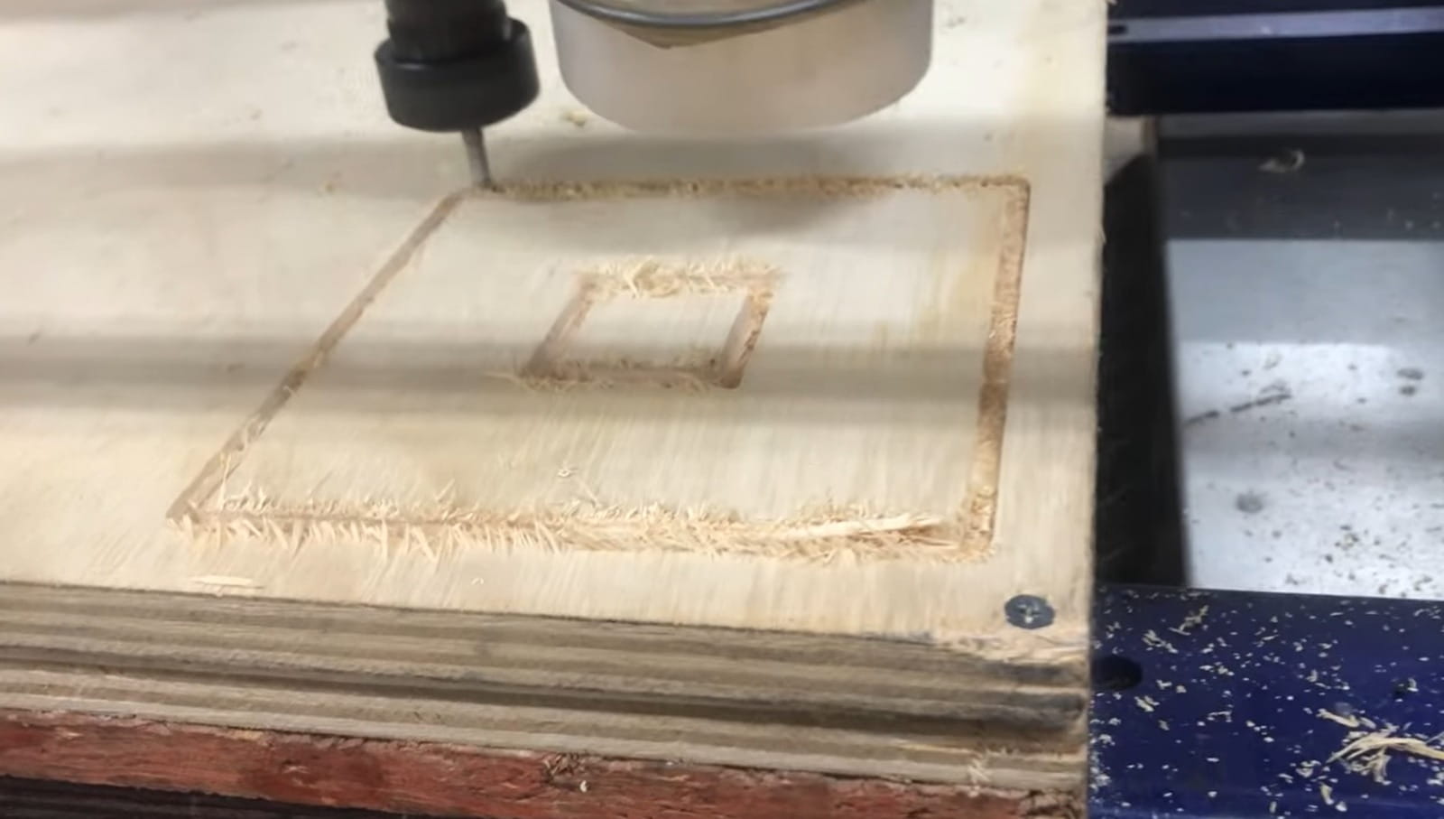
Square test
The square test was used to evaluate the internal fit of a smaller square inside a larger frame. We added dogbones in the internal corners to compensate for the round shape of the milling bit. We also added tabs so that the internal part would remain attached during machining and would not move or fly out during the cut.
Comb test
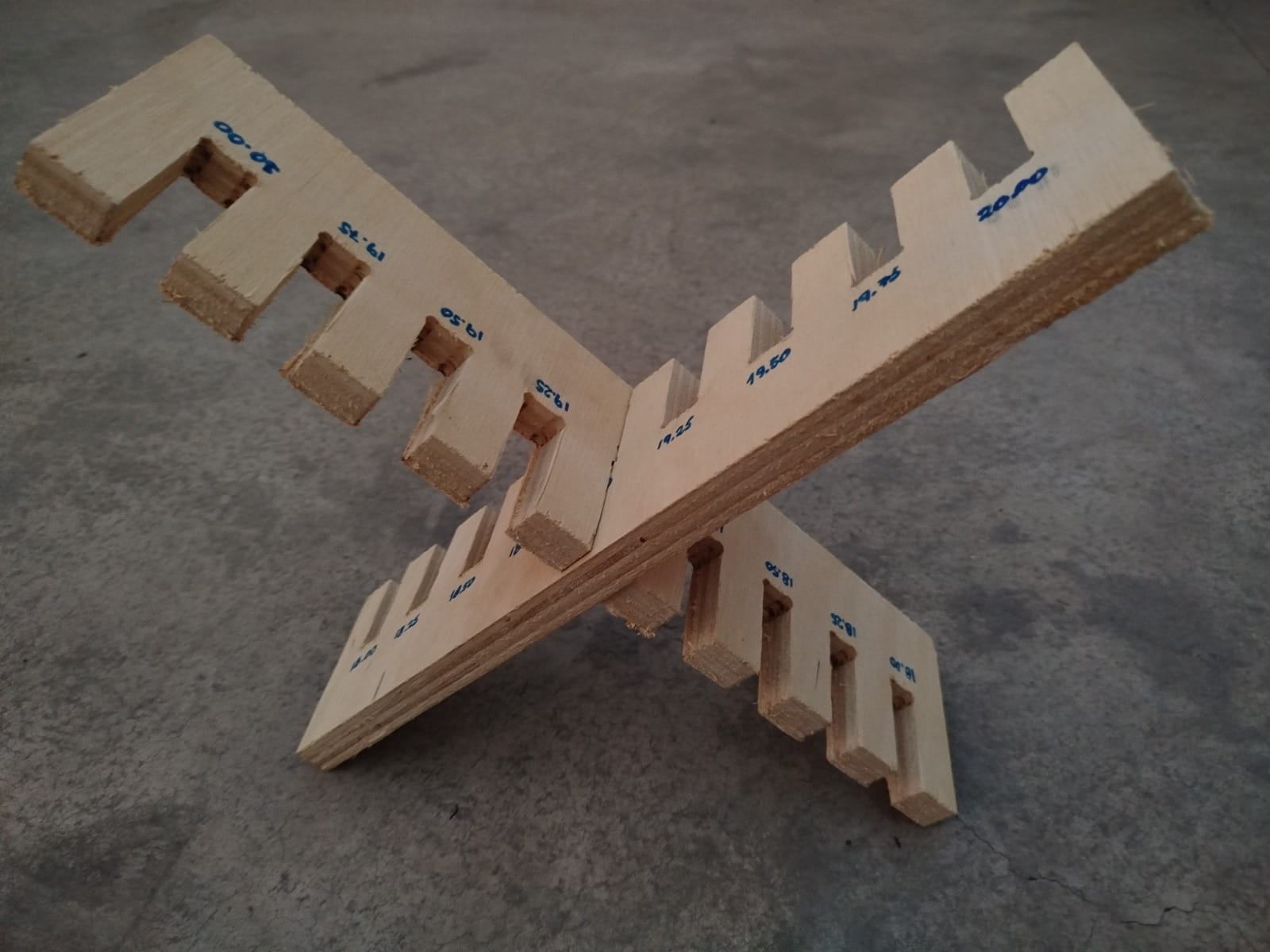
The comb test was used to compare different slot widths and identify the best press-fit according to the real material thickness and machining tolerance. This design included slots of 18.00, 18.25, 18.50, 18.75, 19.00, 19.25, 19.50, 19.75, and 20.00 mm. We also added dogbones in the internal teeth and tabs to keep the internal parts stable during machining.
Problems and solutions
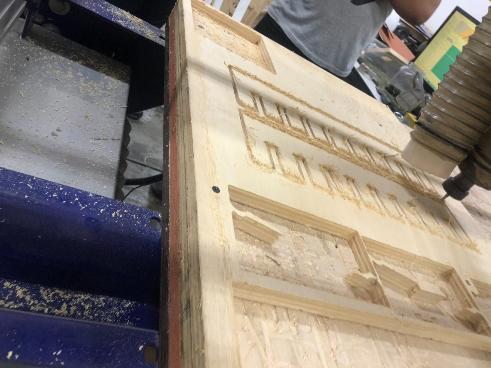
No major problems occurred during the test. The machining process was completed without critical errors such as tool breakage, material displacement, incorrect zeroing, or failed cutting. One important observation was that, after placing the material and making the initial setup, the board had to be fixed with screws, and this required a second calibration step, especially on the X and Z axes. Rechecking the machine reference after fixation was important to maintain accuracy before starting the cut. Another relevant observation was the rough edge finish, mainly due to the plywood structure and the natural tendency of this material to splinter during machining. This was not a machine failure, but rather a material behavior that should be considered in design and finishing stages. To improve assembly, we used dogbones in the internal corners of the square and comb test pieces. This made the internal joints easier to fit and improved the press-fit evaluation. If a smoother result is required in future jobs, possible improvements would include using a better-quality plywood or a different board material, optimizing toolpath direction, adjusting feeds and speeds, using a finishing pass, and sanding the edges after machining.
What we learned as a group
As a team, we discovered that working with a large-format CNC machine involves much more than simply sending a design file to be cut. The process requires proper preparation, attention to safety, accurate machine configuration, appropriate cutting parameters, and secure fixation of the material on the machine bed. We realized that safe operation actually begins before the machine is turned on. Simulating the toolpaths beforehand is crucial to detect potential mistakes before machining the real material. Correctly setting the machine zero is one of the most critical steps in the workflow, and sometimes recalibrating after securing the board is necessary to maintain precision. Additionally, feed rate, spindle speed, and depth of cut have a direct impact on cut quality, machine stability, and tool efficiency. Another important lesson was the value of press-fit testing for identifying the proper tolerance and understanding how joints behave with a specific material. We also learned that dogbone fillets help improve the internal fit of CNC-milled joints. Finally, we observed that material properties play an important role, since plywood can leave rough edges after machining and often requires additional finishing.
Conclusion
This group assignment allowed us to document and understand the workflow of large-format CNC machining using the ShopBot PRSAlpha 96x48. Through this exercise, we practiced safety procedures, prepared material and toolpaths, configured machining parameters, and executed a successful test cut on plywood.
The experience helped us connect digital design with physical fabrication and gave us a better understanding of how machine setup, parameter selection, material behavior, and safety practices influence the final result.
The use of the square test, comb test, and dogbone-adjusted joints made the assignment more useful for evaluating real press-fit conditions, which is valuable for future CNC construction projects.
Individual assignment:
- Make (design+mill+assemble) something big.
Designing my "Press-fit shelf"
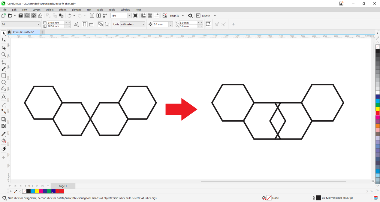
We will design our small floating shelf in 2D using Corel Draw. We will draw 4 hexagons that define the base shape of the furniture and set a reference measurement based on the OSB material thickness that we will use for this shelf.
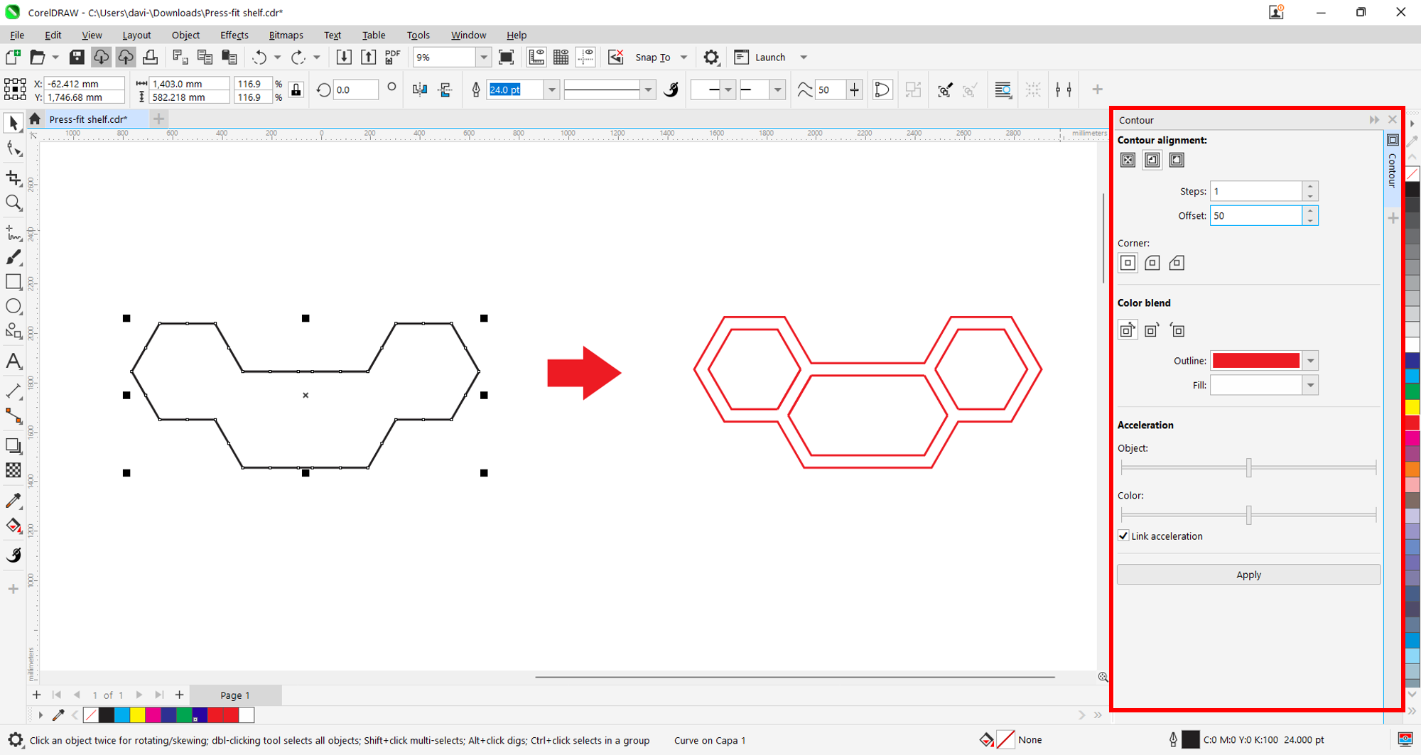
We will create an outline of the base and then apply a 5 cm offset.
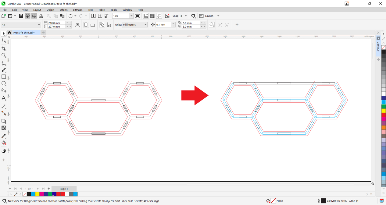
We will draw the front joints by defining the material thickness and tolerance. In this case, we used 18 mm OSB, then we will draw the box structure of the shelf as a guide.
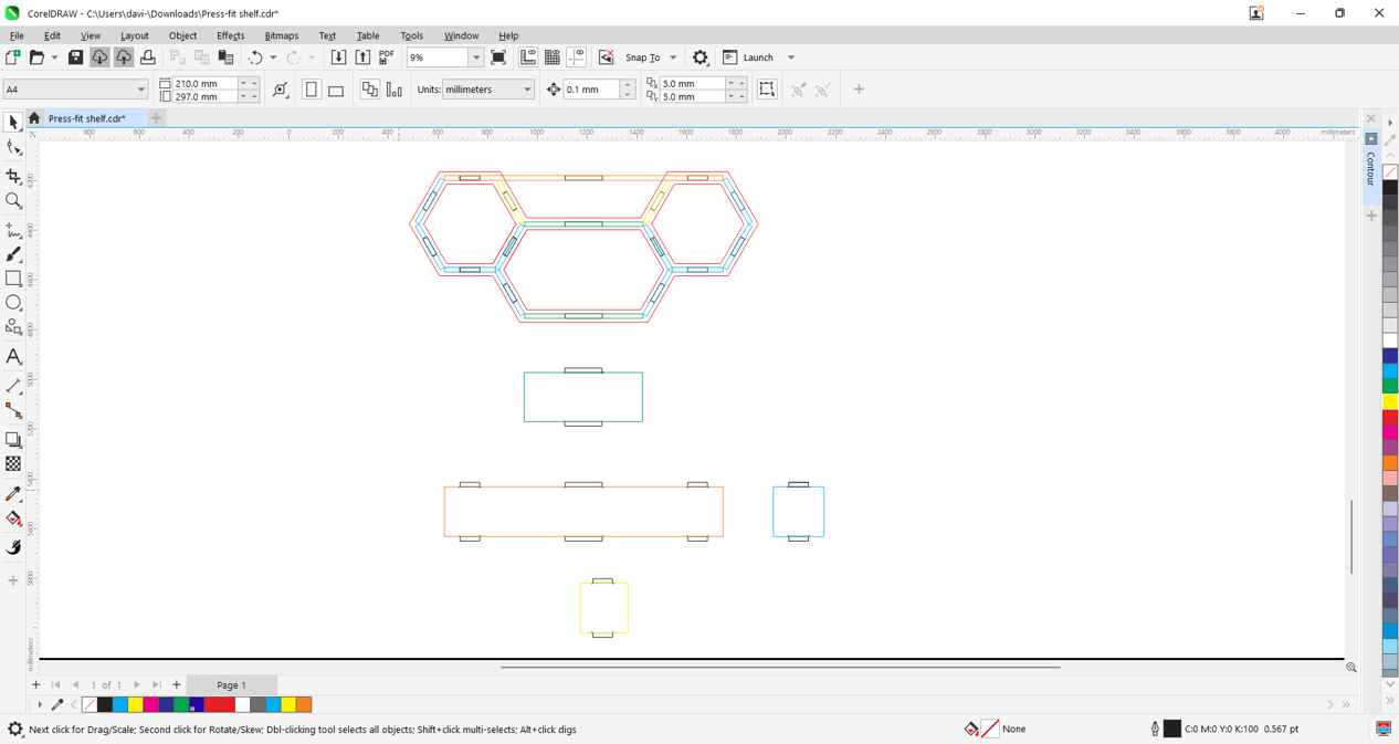
Using the assembly guides, we will measure and draw each part of the shelf box.
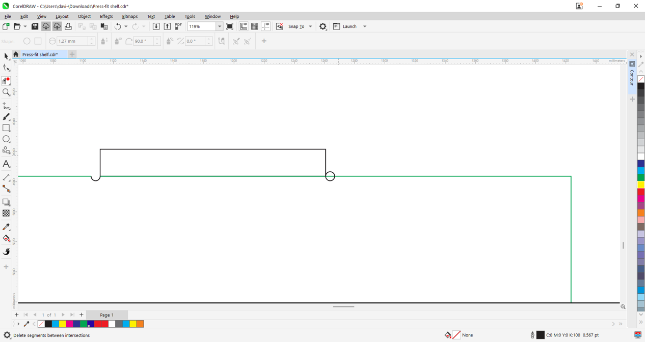
We will also draw the "dogbone" notches for optimal router-fit joints.
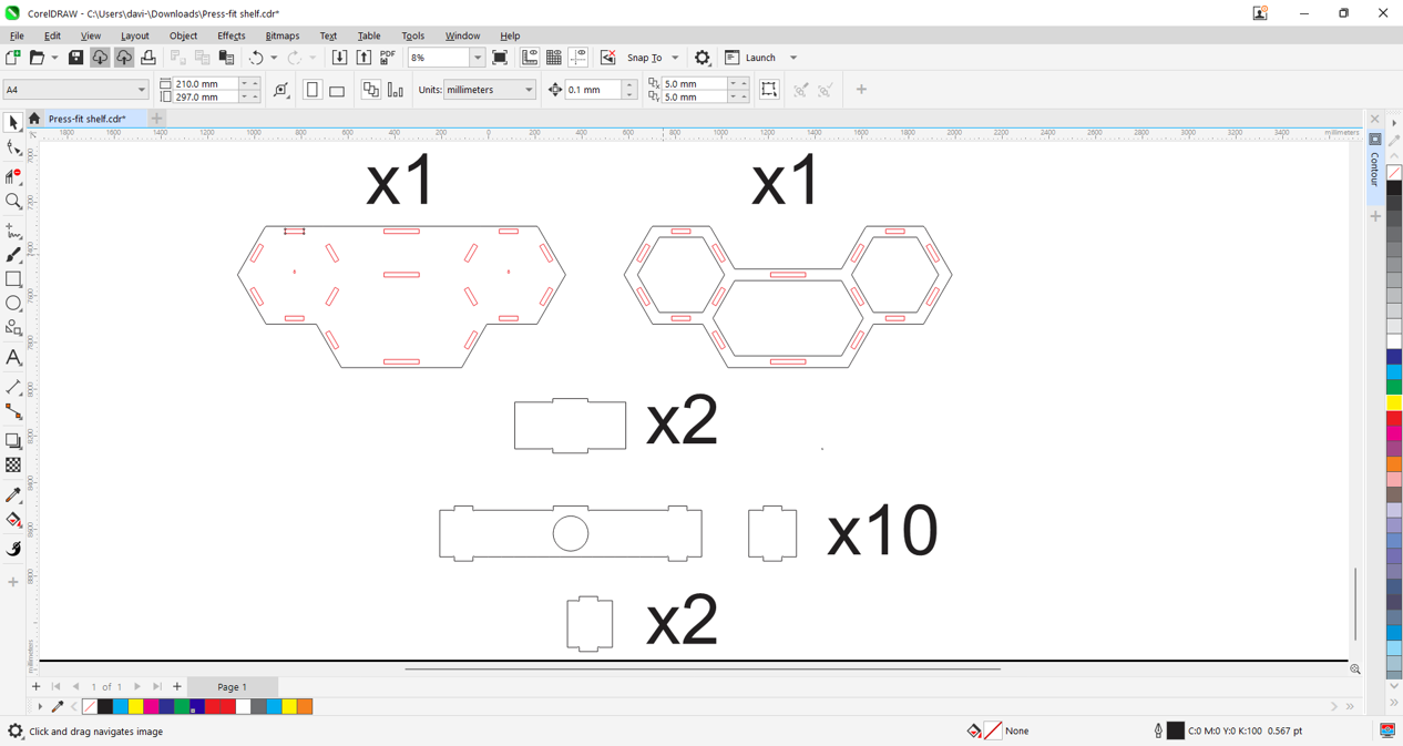
Now we will make a parts count by numbering the required quantities for the shelf.
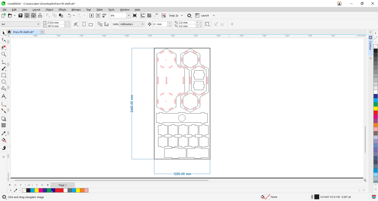
We will place and organize all parts optimally. The sheet size is 122x244 cm, and the piece thickness is 18 mm, so the cutting area format is 118x240 cm.
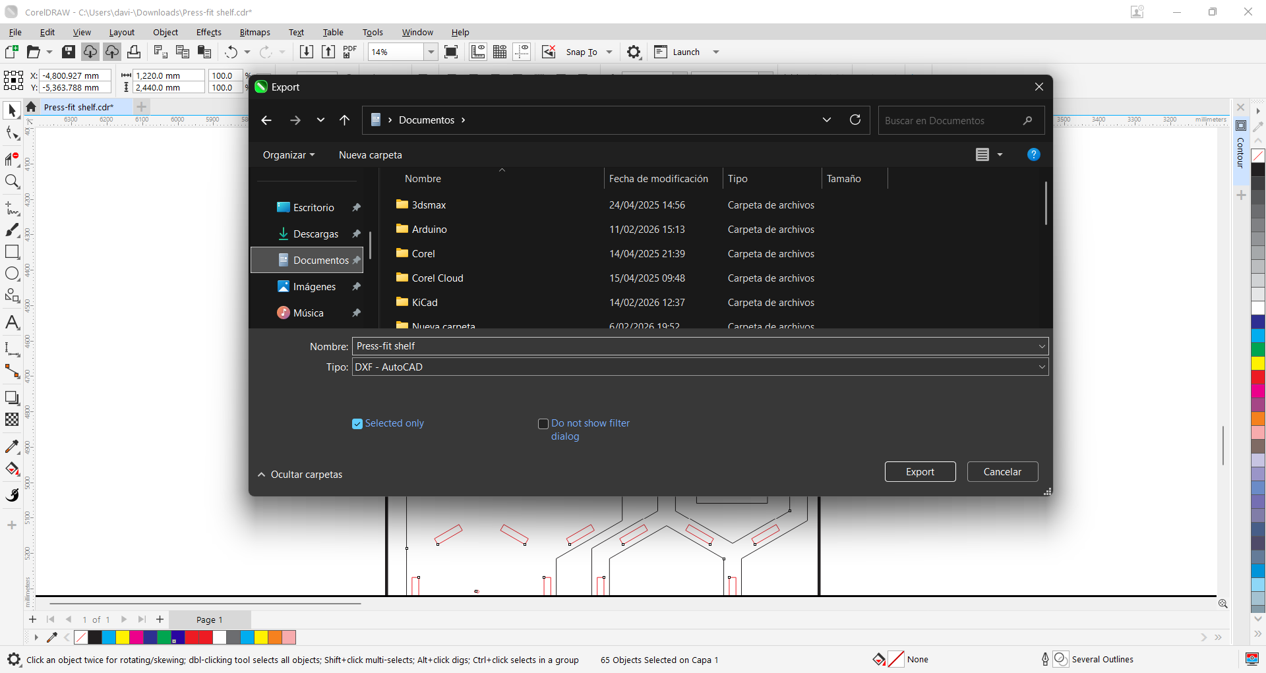
We will export our design in DXF format so we can import it into our cutting software. In this case, we will use Vectric Aspire.
Machining with "Aspire"
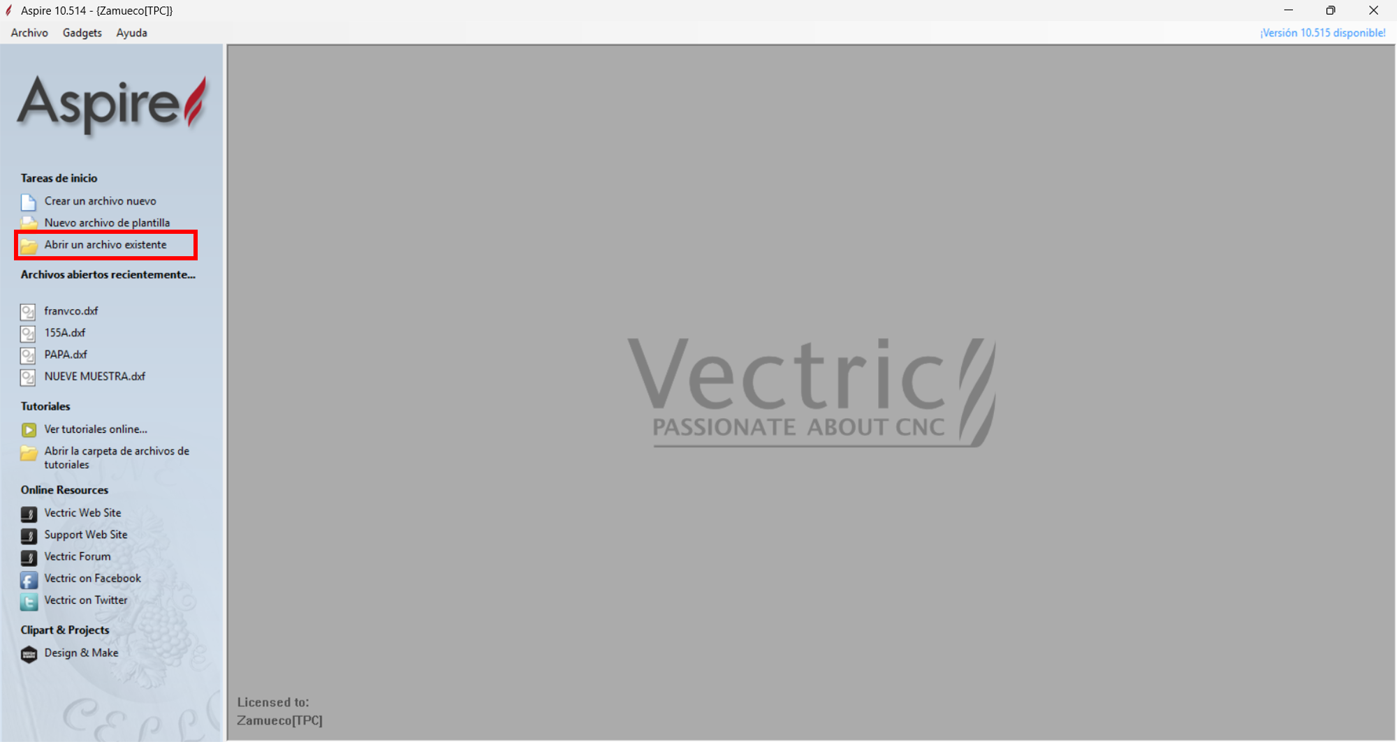
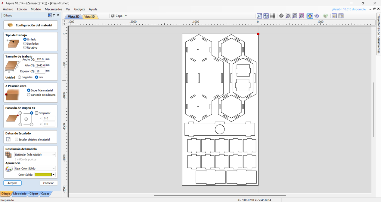
We will open a new file and locate our exported .dxf, import it, and fit it to our cutting format. Then we will set the machine origin points.
Click to open an existing file. We import the .dxf file and configure the general parameters.
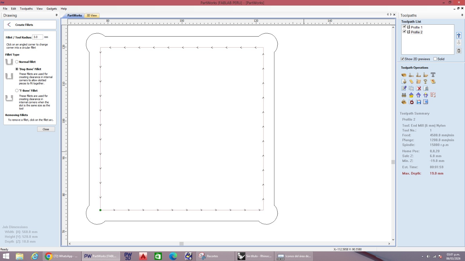
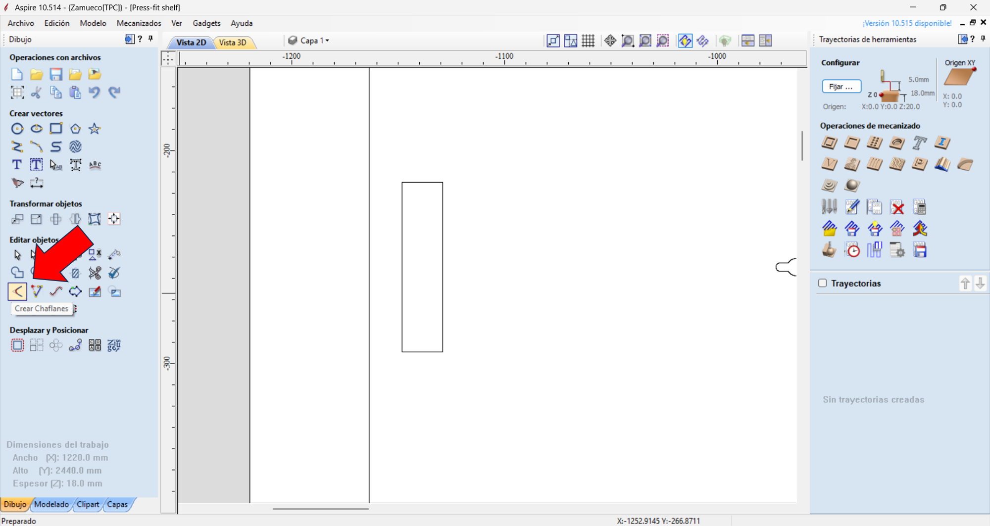
In this case, we will use the "Dogbone" command on the missing joints because it is easier to create them in Aspire. We will do this for all missing ones, remembering that our end mill has a 3 mm radius.
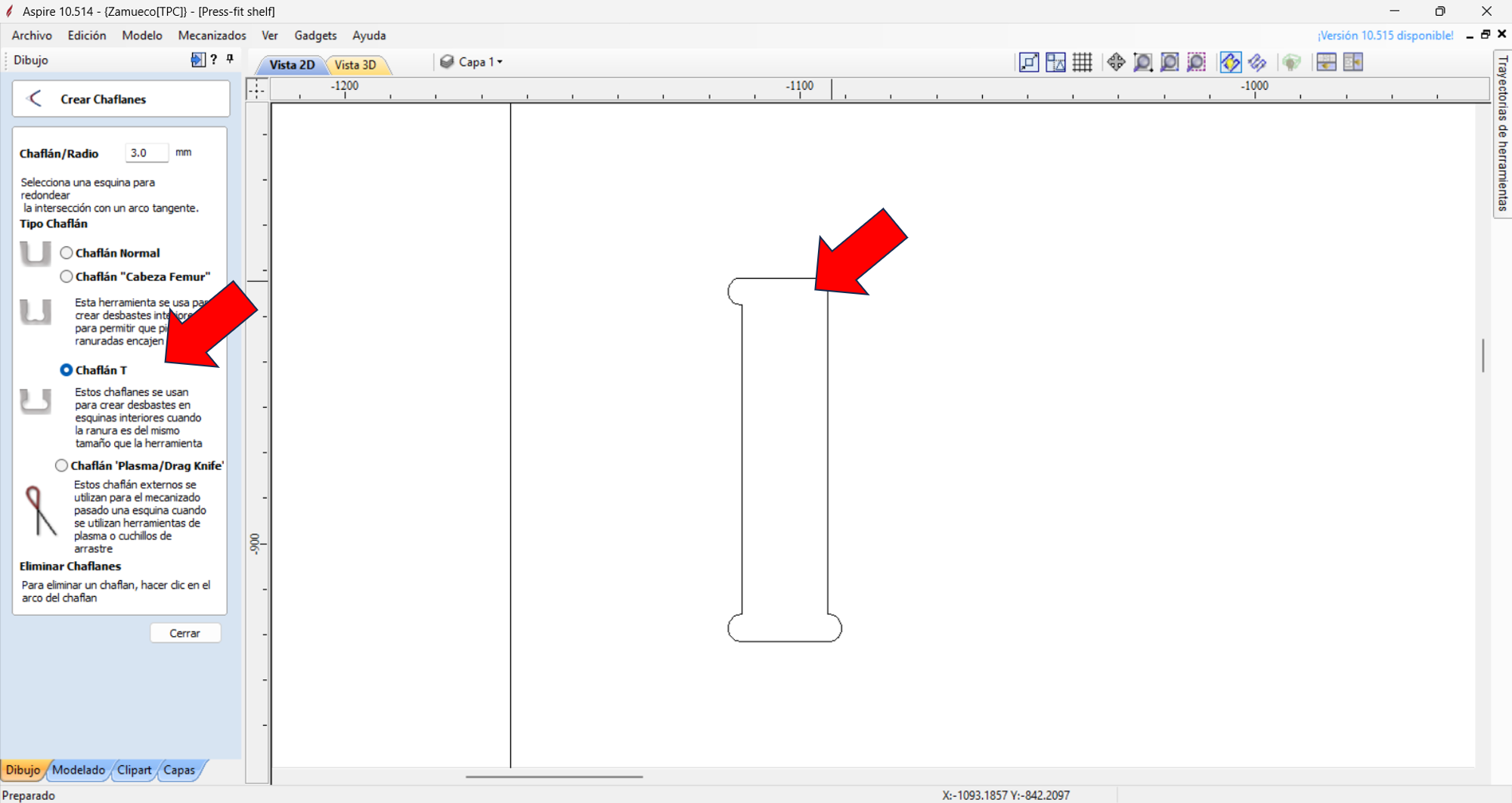
Click to create the chamfer. We choose the T-bone chamfer and click on the corners.
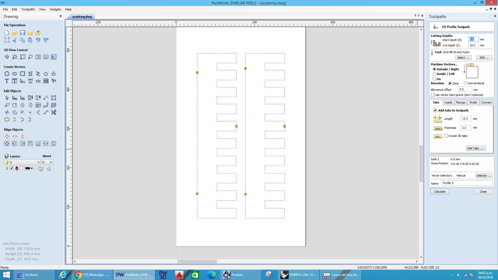
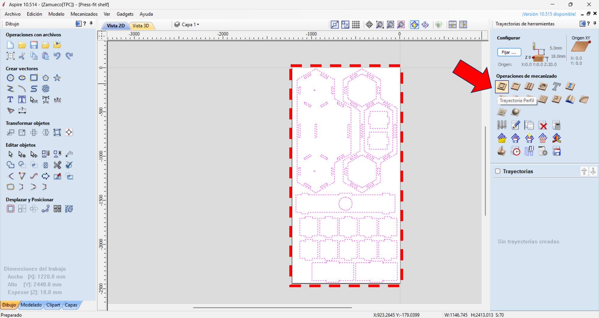
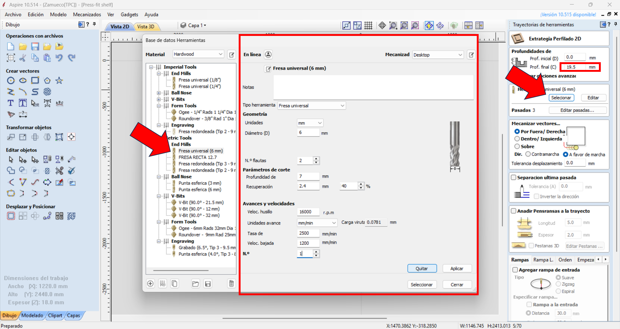
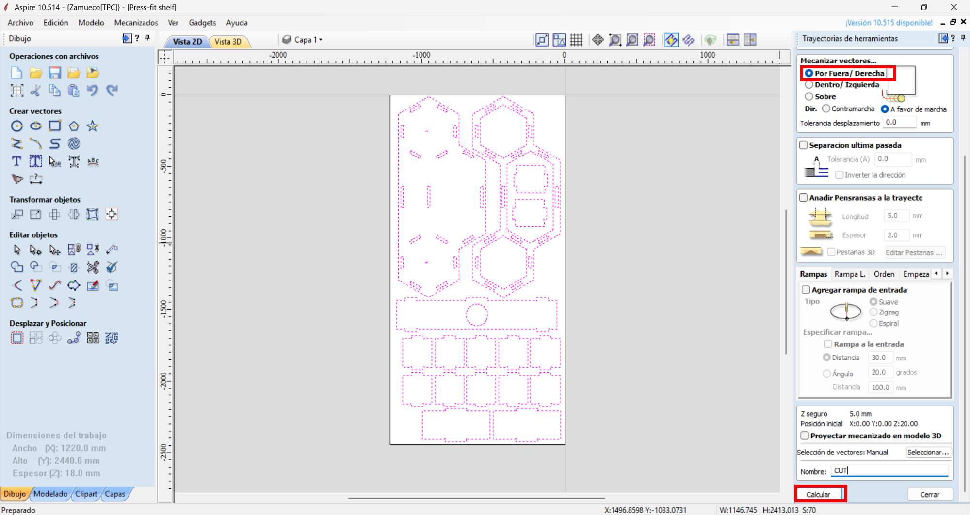
Then we will select all vectors to machine and click "Profile Toolpath," choose the end mill to use (in this case 6 mm), and set cut depth, feed rate, and spindle speed. Then we click "Accept" and the machining toolpath will be generated.
6 mm end mill, profile toolpath, 18 mm OSB board, and outside cut strategy. RPM: 16000, Feed rate: 2500 mm/min, Depth per pass: 7 mm
In this case, we will use the outside cut to cut the parts. We will verify that interior cuts are also correct. The end mill and material allow us to avoid using holding tabs. Once checked, we click calculate.
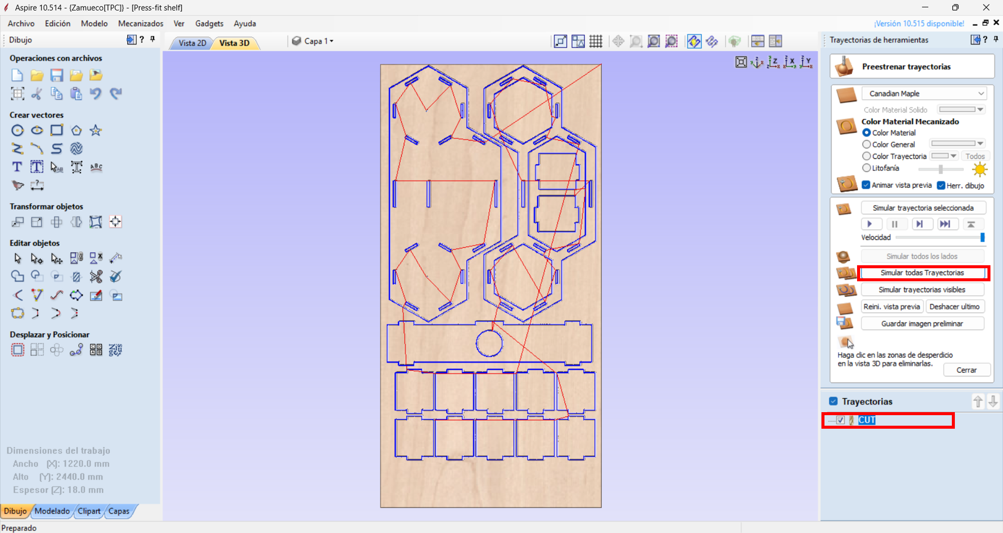
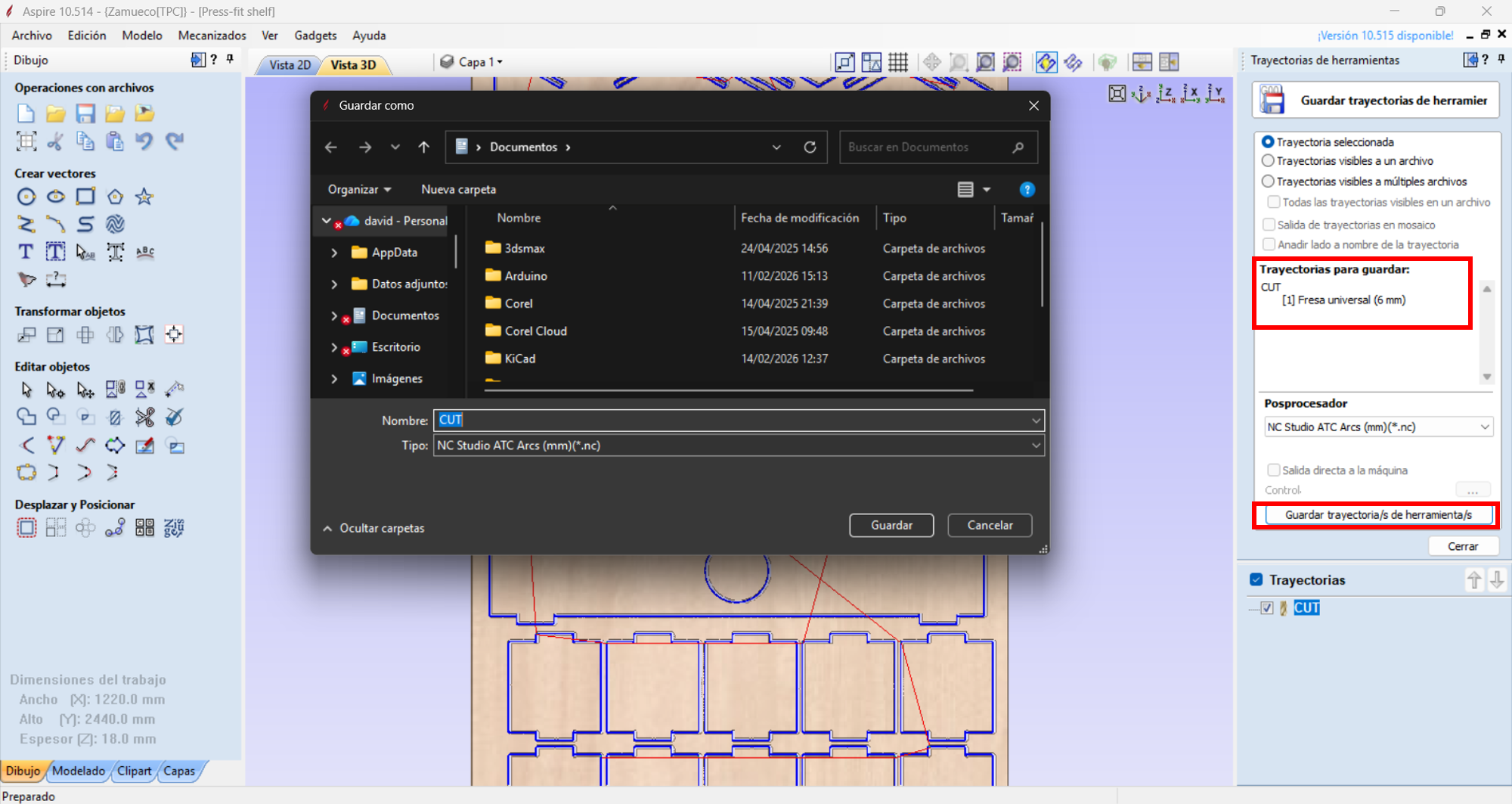
We will simulate our machining toolpath to verify there are no errors, and once verified, we will export the G-code to machine our project.
We will use the NC Studio post-processor in millimeters (.tap) and click save toolpath.
Cutting with a CNC router
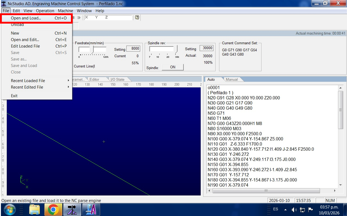
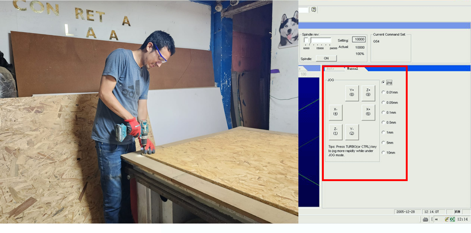
We will open NC Studio and load our code.
We will place our OSB board and secure it with screws, then position the tool to set the 0 origin for the X, Y, and Z axes.
Once positioned, we click "Start" and the machine begins machining our project. The machining process took approximately 40 minutes because we did it in 3 depth passes.
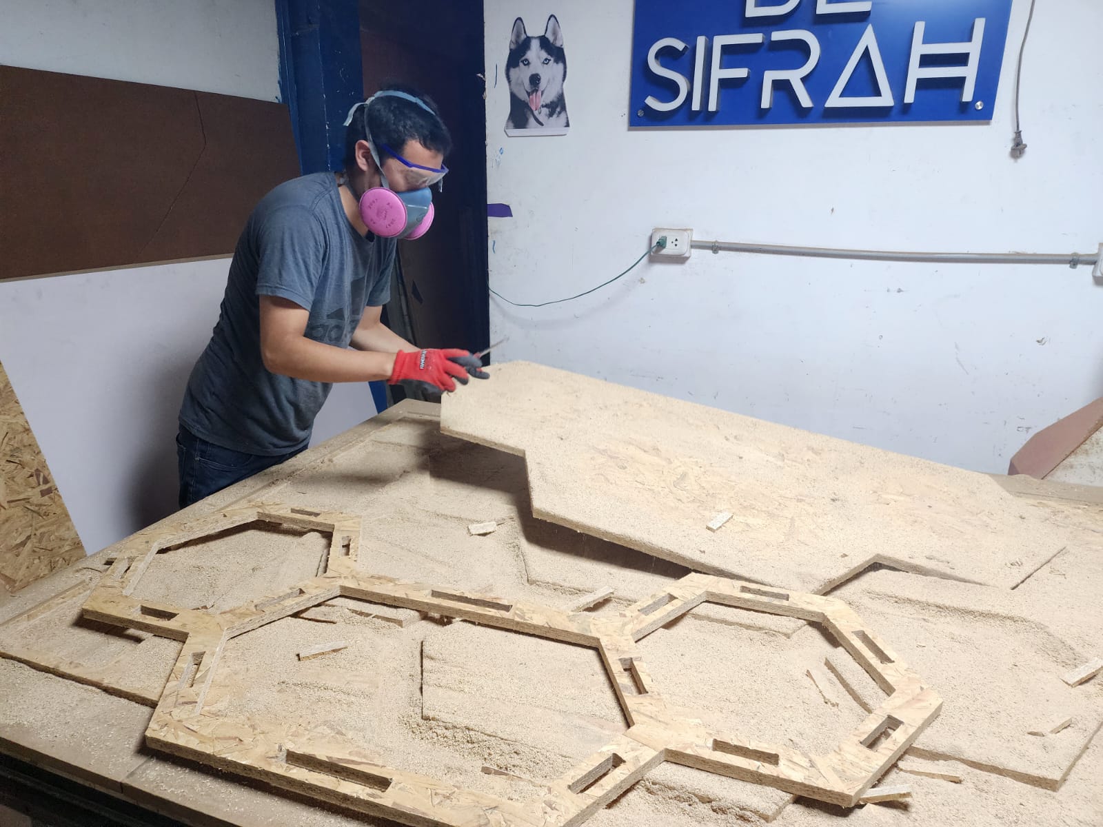
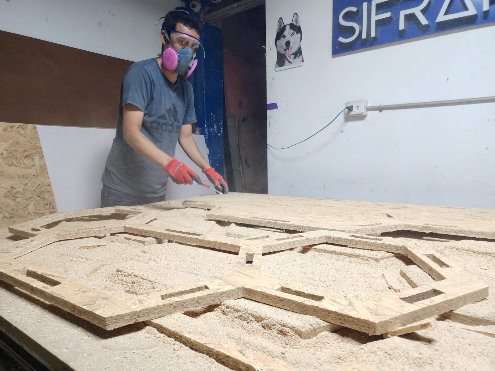
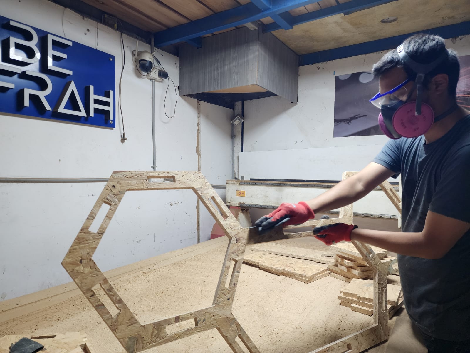
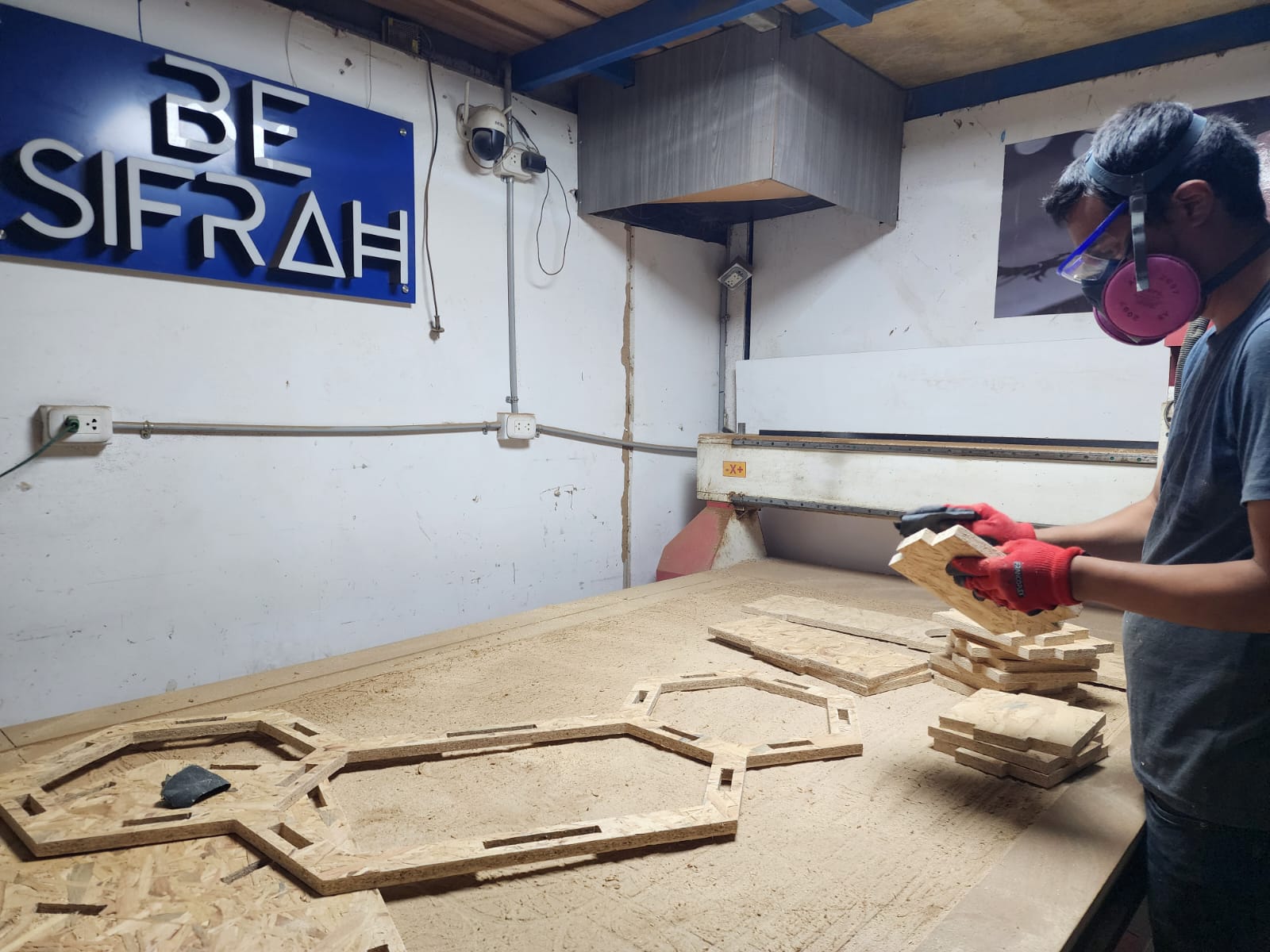
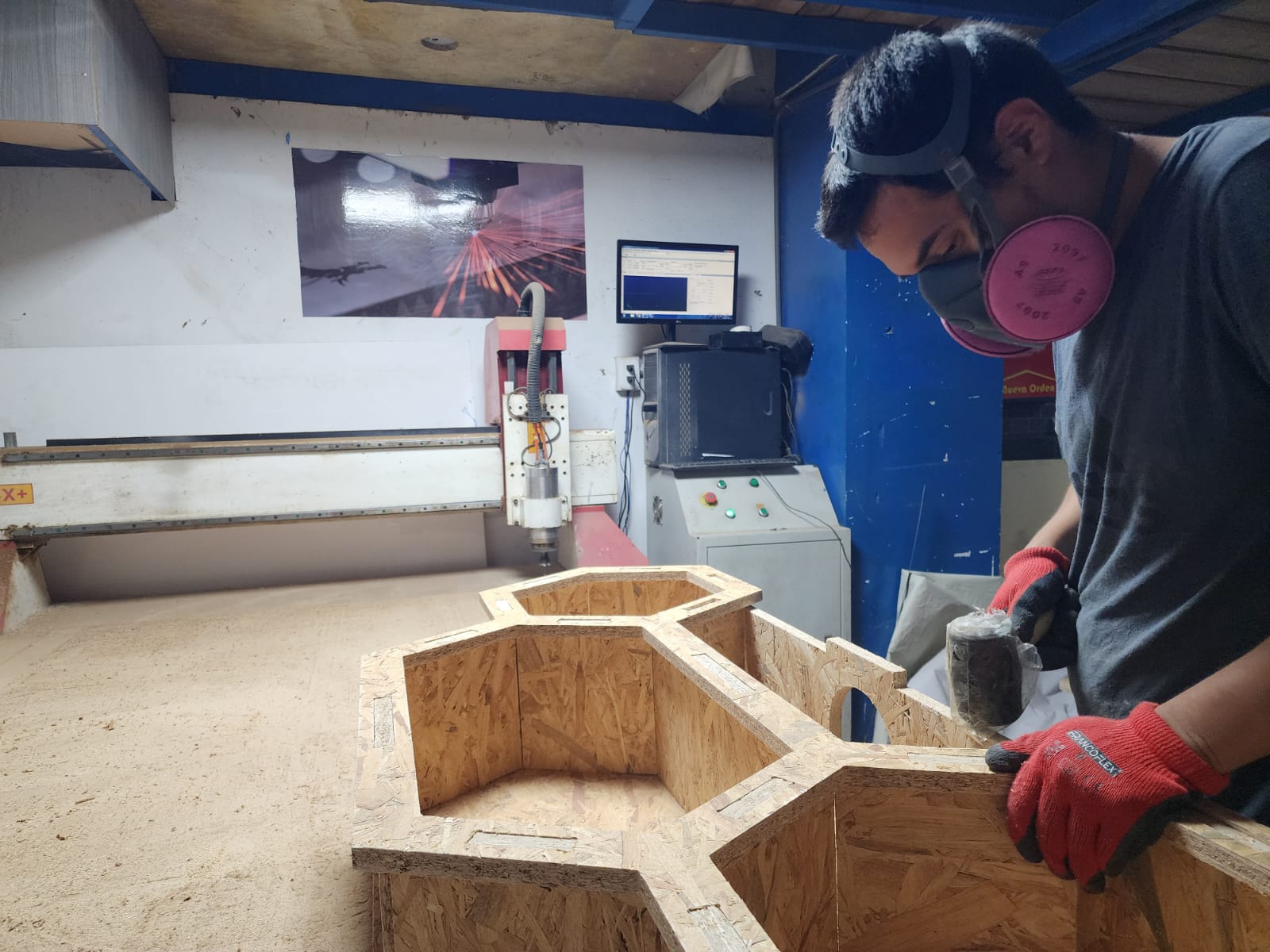
After machining, we removed the parts carefully.
We sanded both sides of the cut edges using 80-grit wet sandpaper.
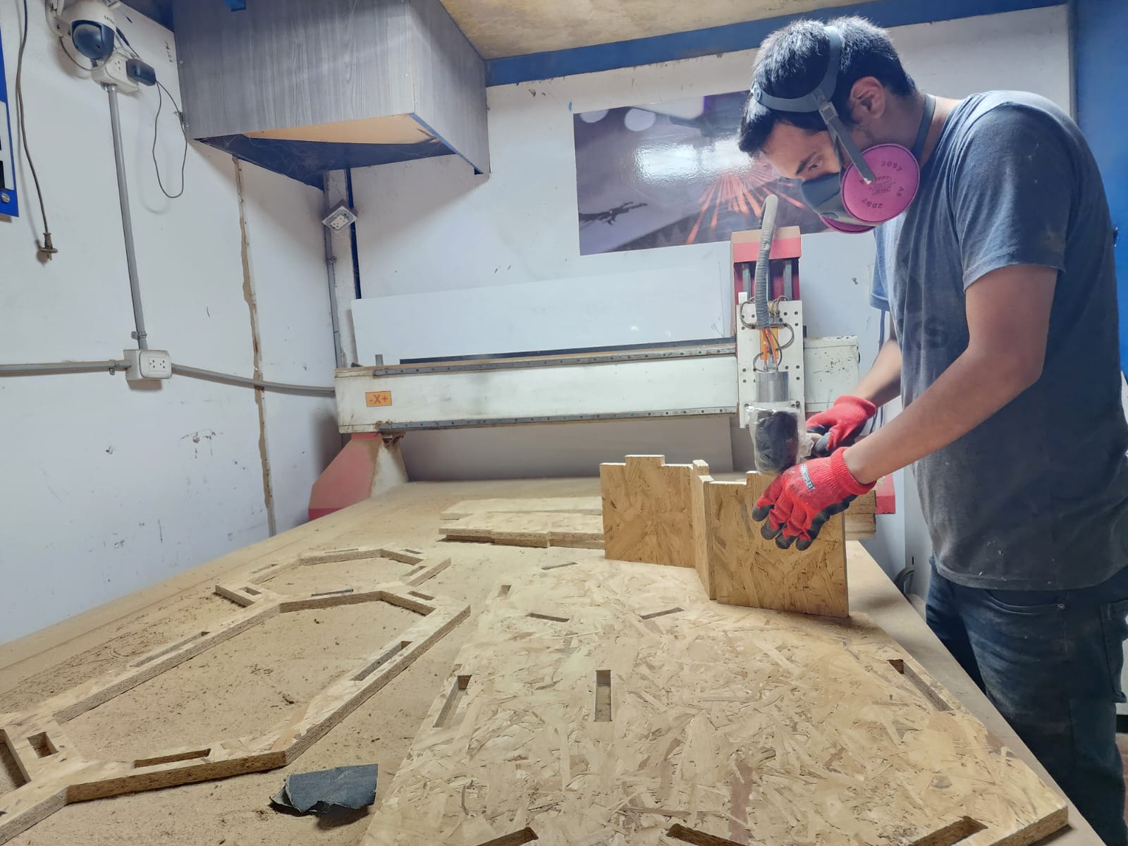
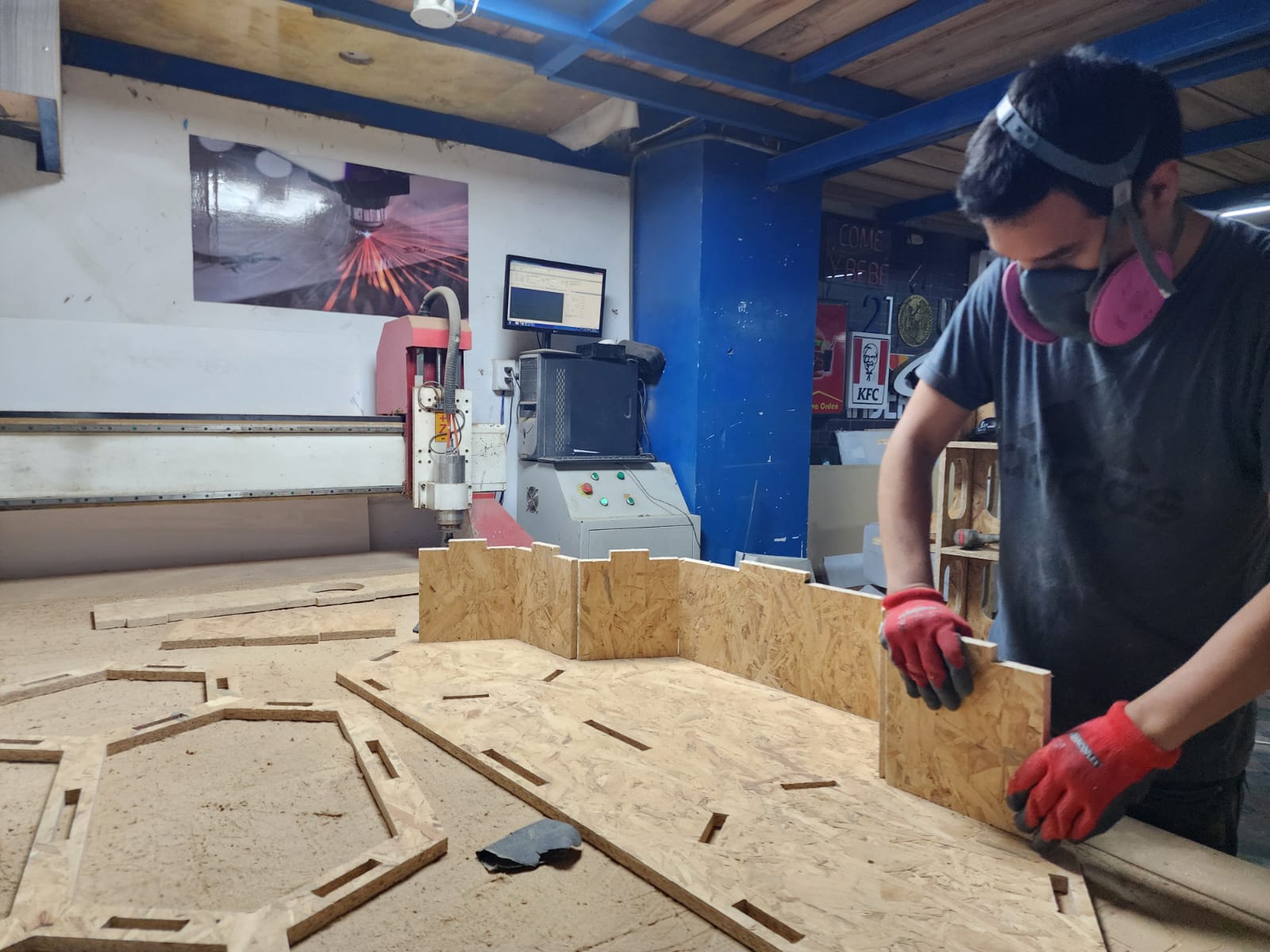
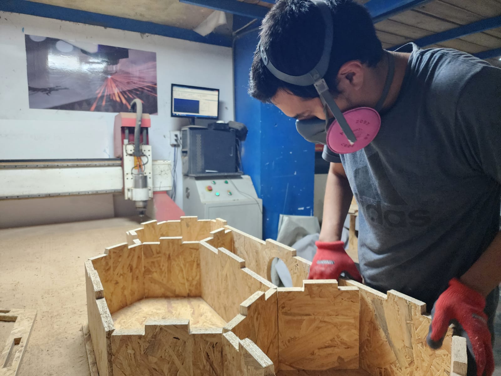
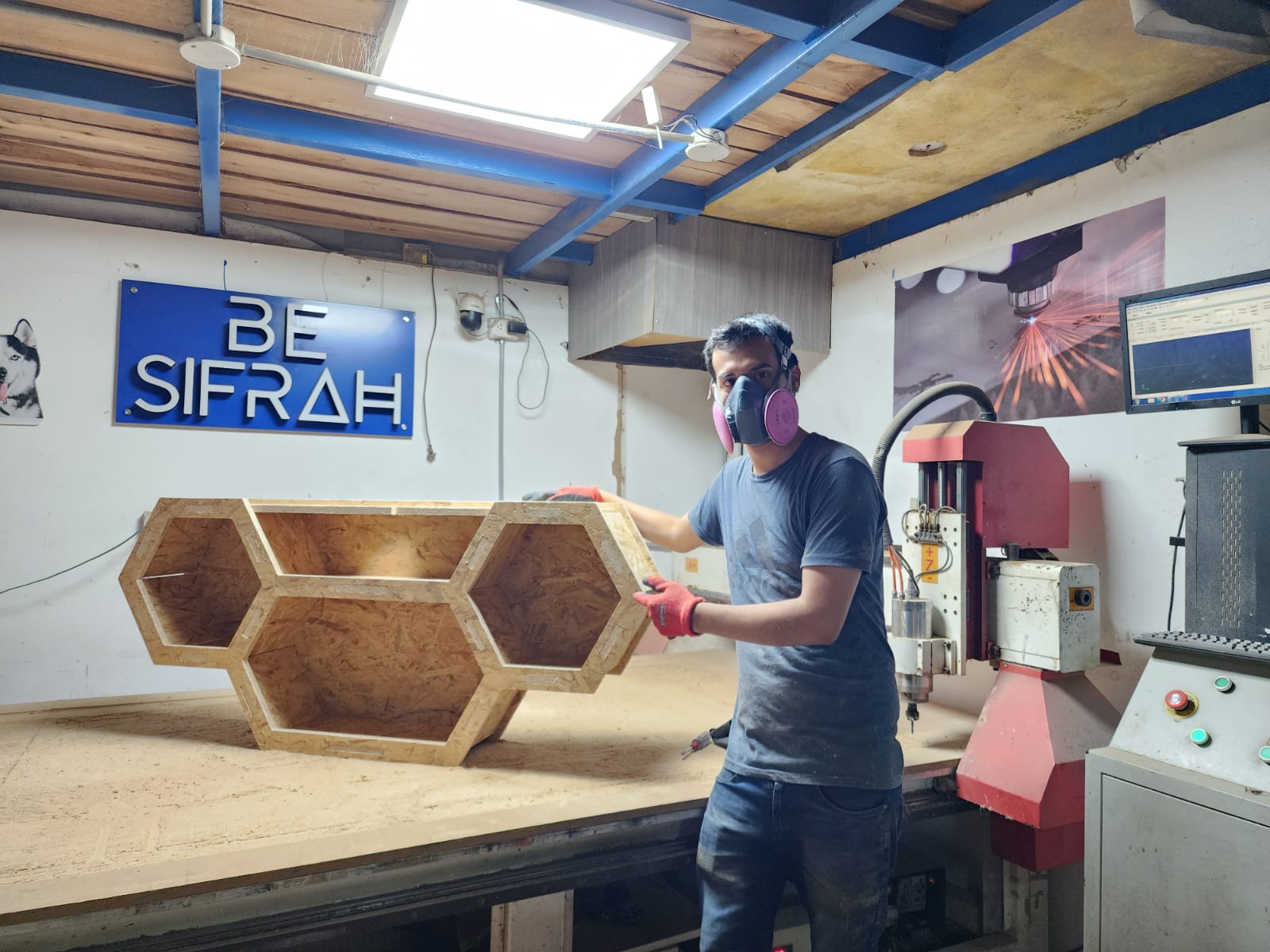
We proceed with assembly, using a rubber mallet to fit the parts together. It is important to do this carefully to avoid damaging the part edges.
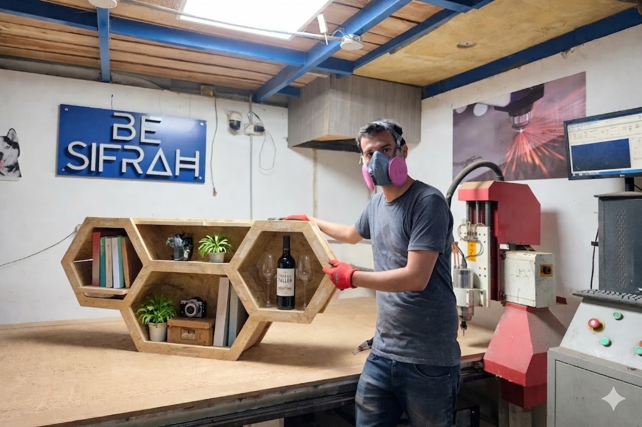
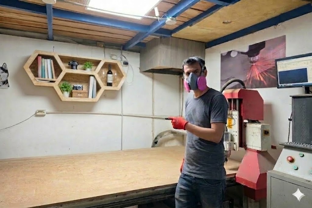
FINAL RESULT!!!
FINAL RESULT WITH AI XD...!!!
Prompts for AI image generation (GEMINI):
FINAL RESULT WITH EXTREME AI XD...!!!
Conclusions:
Machining note
CNC cutting parameters
Parameter
Value
Tool
Universal end mill, 6 mm
Final cut depth
19.5 mm
Depth per pass
7 mm
Number of passes
3
Spindle speed
16000 rpm
Feed rate
2500 mm/min
Plunge rate
1200 mm/min
Stepover
2.4 mm (40%)
Chip load
0.0781 mm
Prompts for AI image generation (GEMINI):
FILES