WEEK 08
Electronics Production
Group assignment:
- Characterize the design rules for your in-house PCB production process: document the settings for your machine.
- Document the workflow for sending a PCB to a boardhouse.
- Document your work to the group work page and reflect on your individual page what you learned.
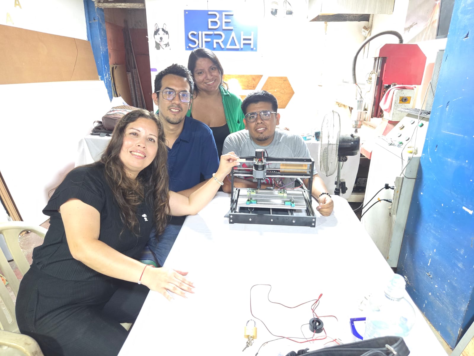
What I Learned From Teamwork
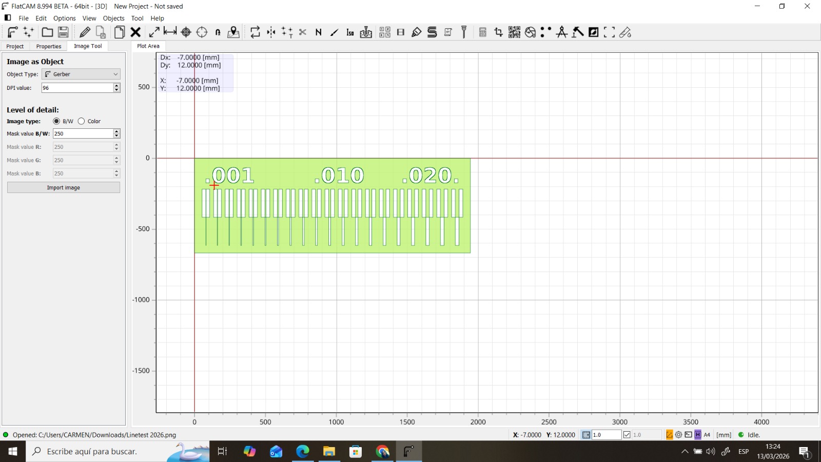
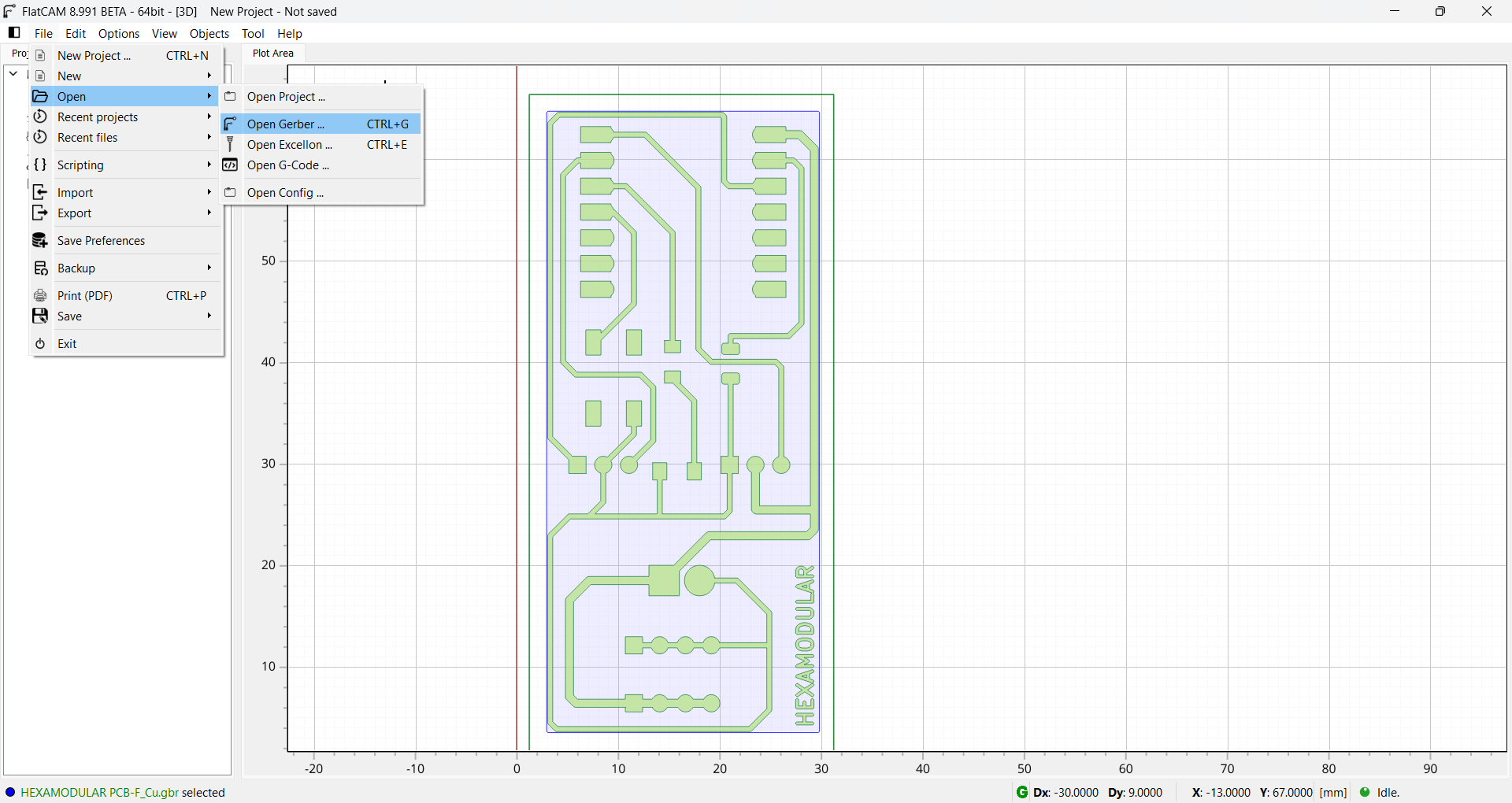
Using the FLATCAM Program.
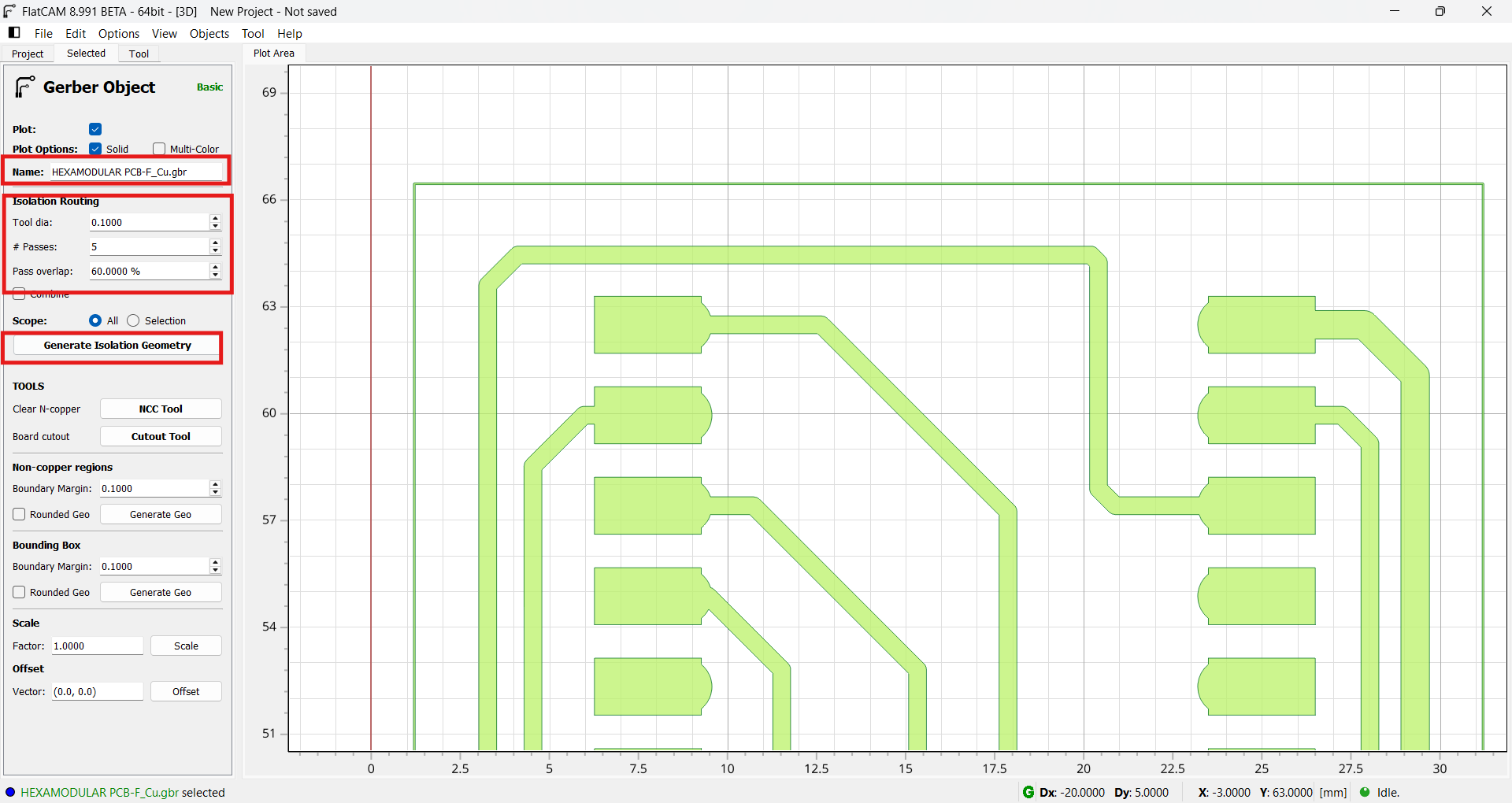
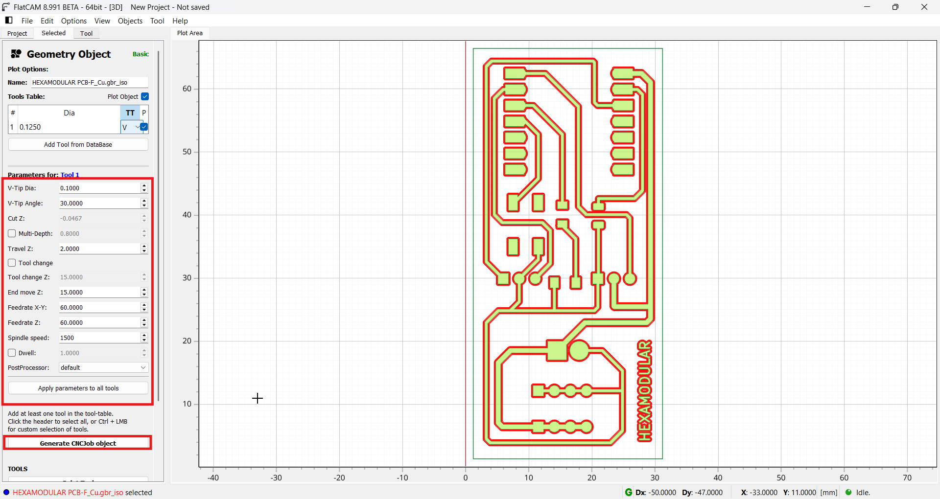
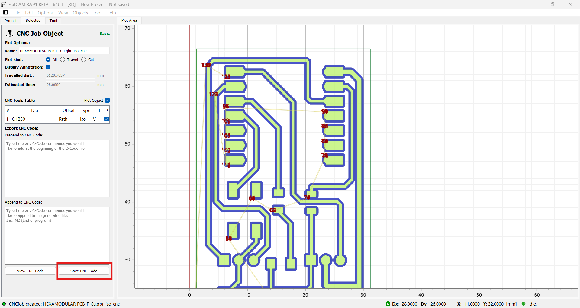
FlatCAM allowed us to open our GERBER files and prepare them for PCB production. In this case, we performed a minimum trace-width test to evaluate what our CNC can achieve. FlatCAM also lets us generate machining files to send to any CNC mill. We ran two tests, one with the image mirrored because our base file was in .PNG format. We configured the engraving and cutting bits according to the required angle and depth.
Calibration with Automatic Z and Manual Z.
There is a slight difference between calibrating the Z axis with the automatic calibration system and doing it manually. Automatic calibration uses sensors to detect the material surface and adjust tool height accordingly, which can be faster and more convenient. However, manual calibration allows more precise control over tool height, which can be useful for irregular materials or to achieve a specific finish. In general, automatic calibration is suitable for most applications, but manual calibration may be preferable when higher precision is required or when working with difficult materials.
Results Analysis
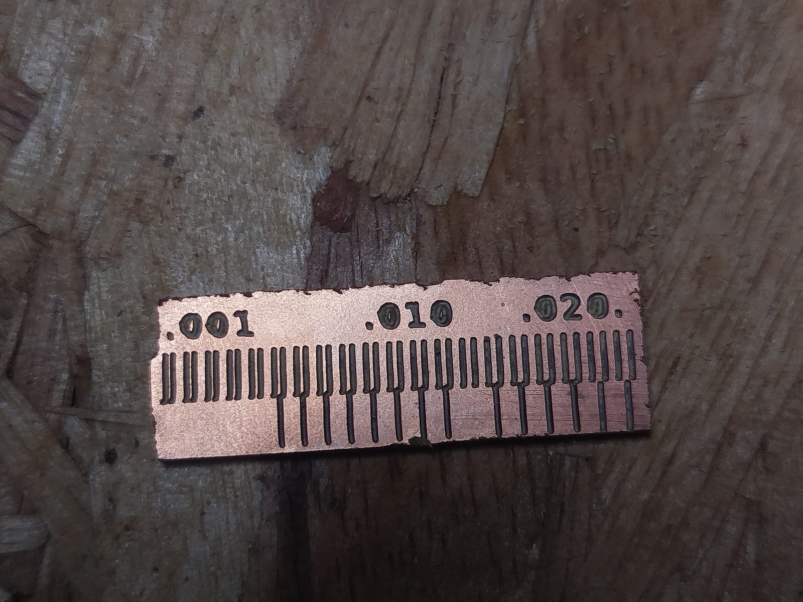
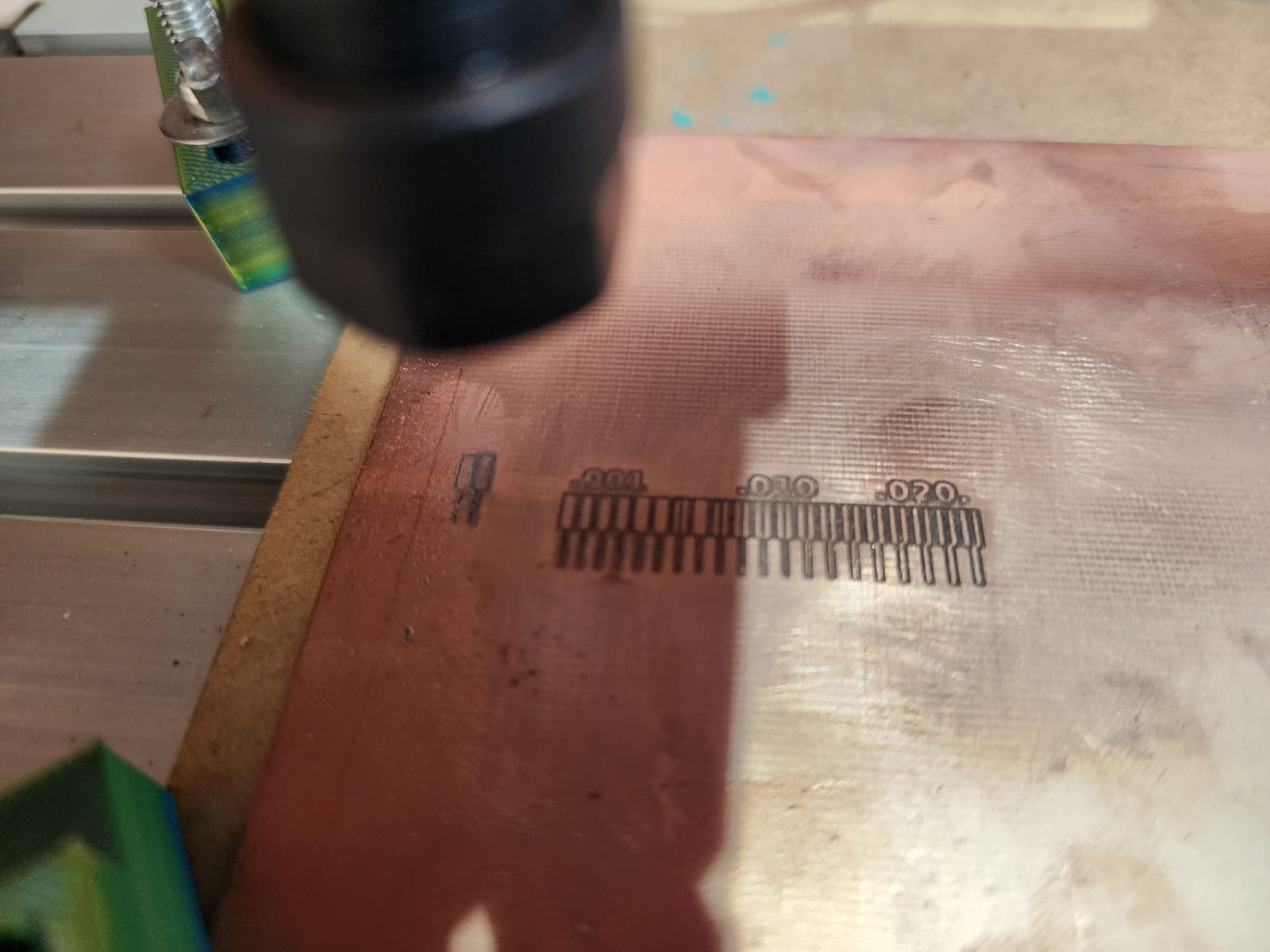
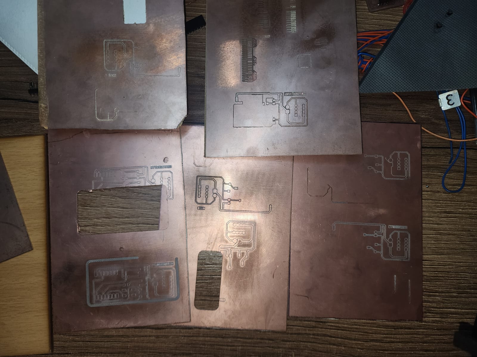
A thickness-rule test was used to compare the minimum trace width the machine can achieve with a 0.1 mm, 30° V-bit. This design included line widths from 0.001 to 0.20. Because dogbones were not added and clamping was not secure, the board moved during machining, which resulted in an imprecise cut.
Conclusion
In conclusion, the thickness-rule test allowed us to evaluate the performance of our CNC machine using a 0.1 mm V-bit with a 30° angle. Although it was possible to cut very thin lines, poor clamping and the absence of dogbones caused the board to move during machining, resulting in an imprecise cut. To improve future results, it is crucial to secure the material firmly and include dogbones to prevent unwanted movement during the cutting process.
Unfortunately, the TT3018 machine had connection errors that made further testing impossible, but with better clamping and dogbones, more accurate results are expected in future tests.
Individual assignment:
- Make and test a microcontroller development board that you designed.
FLATCAM PCB PRODUCTION
This time I used FlatCAM. I loaded the GERBER file of my test board, configured the tools for engraving and cutting, and finally exported the machining files to send them to the CNC. Z-axis calibration was done with both automatic and manual methods to compare results. Unfortunately, the board moved during machining, which resulted in an imprecise cut, but with better clamping and the inclusion of dogbones, more precise results are expected in future tests.
We create the toolpath by setting the dimensions of our bits and the pass overlap percentage.
We configure the highlighted parameters with the corresponding bits, feed rates, and RPM of the CNC we are using.
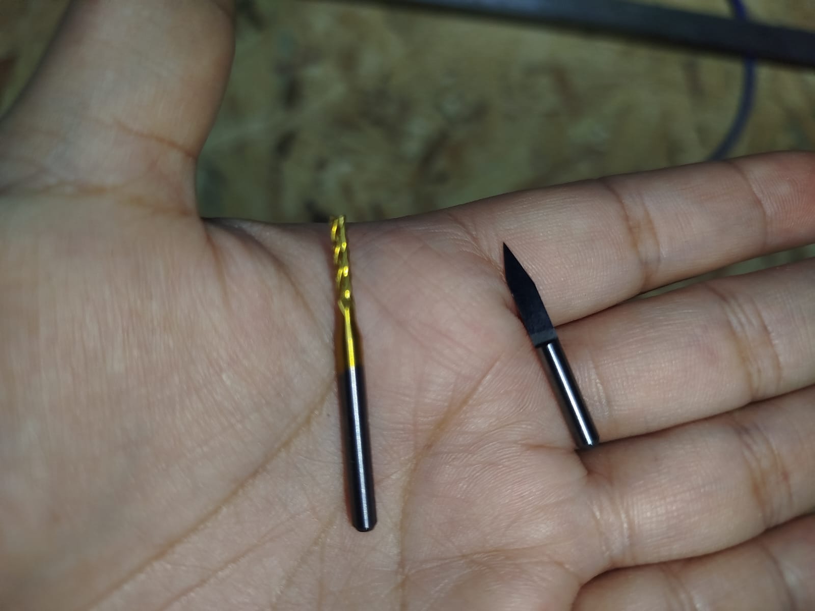
We use the 2mm carbide PCB cutting milling cutter and the 0.1mm spear point milling cutter for engraving.
We export the G-code generated by the design software to the CNC.
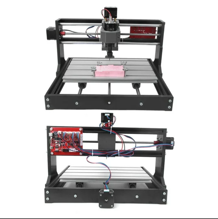
THE TT3018 CNC IS NOT RECOMMENDED!!
Although there are several versions and quality levels, the one I used had connection errors and electrical noise, causing the machine to freeze during machining. I also read that the same thing happens to other people. I still tried and used Candle to load the G-code.
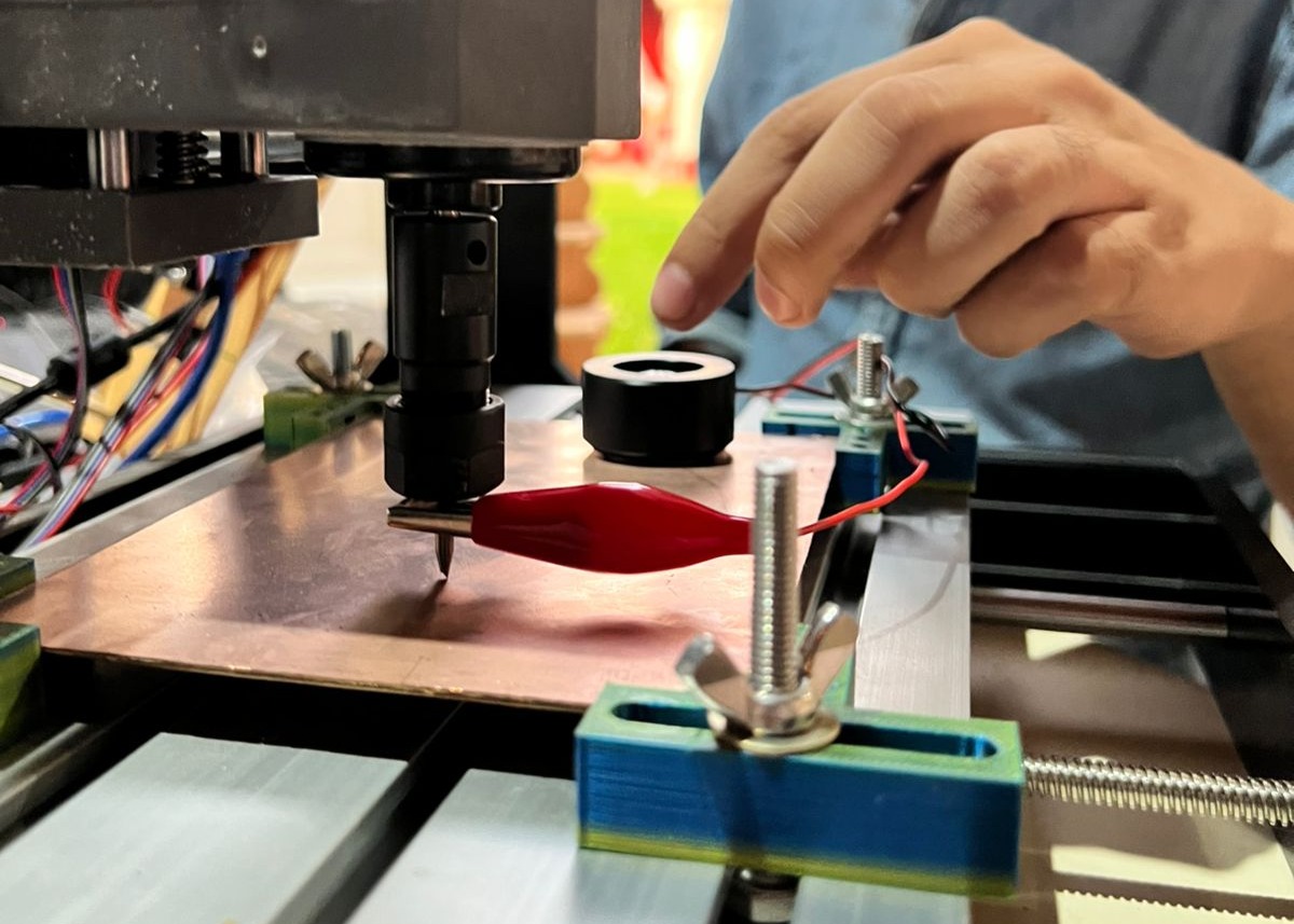
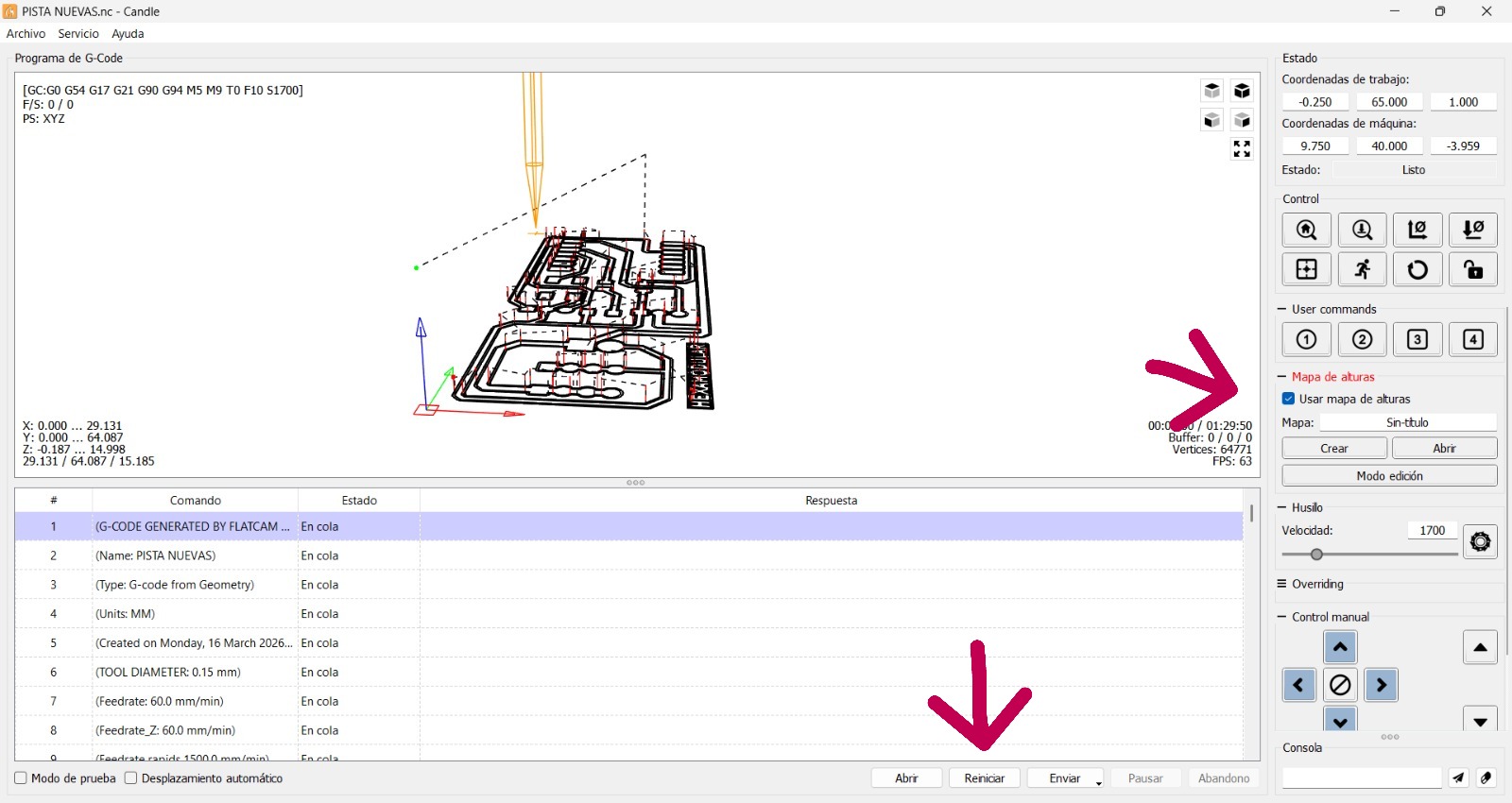
We open our G-code in Candle and move to the work area. We install the automatic Z probe as shown in the photo. We also use a 0.1 mm, 30° V-bit for track engraving and a 2 mm flat end mill for cutting. Then we click Create to generate the Z height map. A window opens to configure the height map; in this case I set it to 5 mm depth and 5 mm step. Next, another window opens to configure the area to map; I used a 10 mm margin on each side. Finally, a new window appears to configure the map type; I left it as a normal height map. The height map is then displayed and can be saved for future machining jobs.
We check the height map option and then click "start" to begin machining.
THE TT3018 CNC IS NOT RECOMMENDED!!
I MADE MANY ATTEMPTS, BUT THE MACHINE KEPT STOPPING AND DISCONNECTING. I TESTED MANY CODES WITH SHORTER TOOLPATHS, BUT NOTHING WORKED. I STILL NEED TO COMPLETE THE ASSIGNMENT, SO I WILL TRY ANOTHER MACHINE.
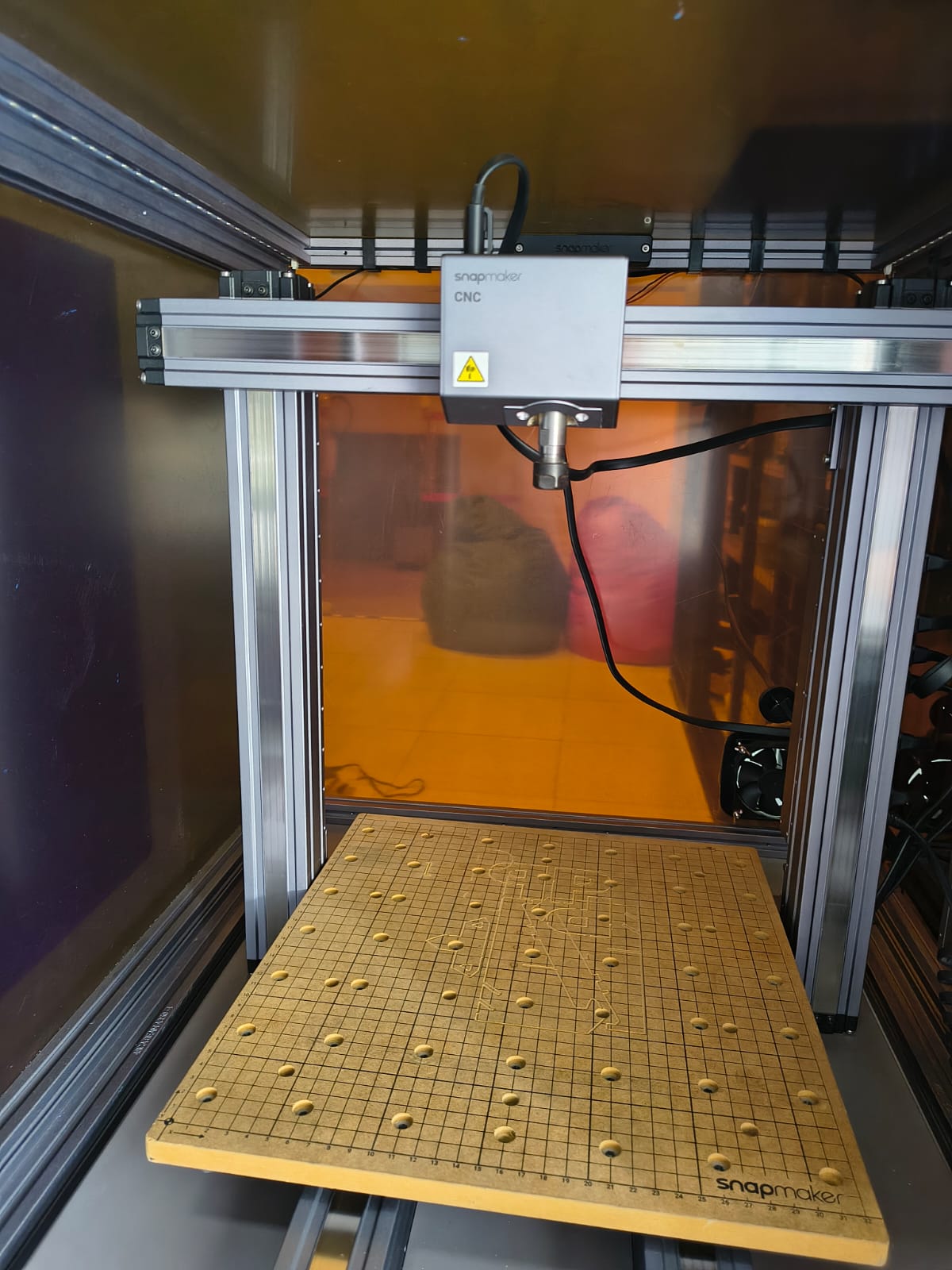
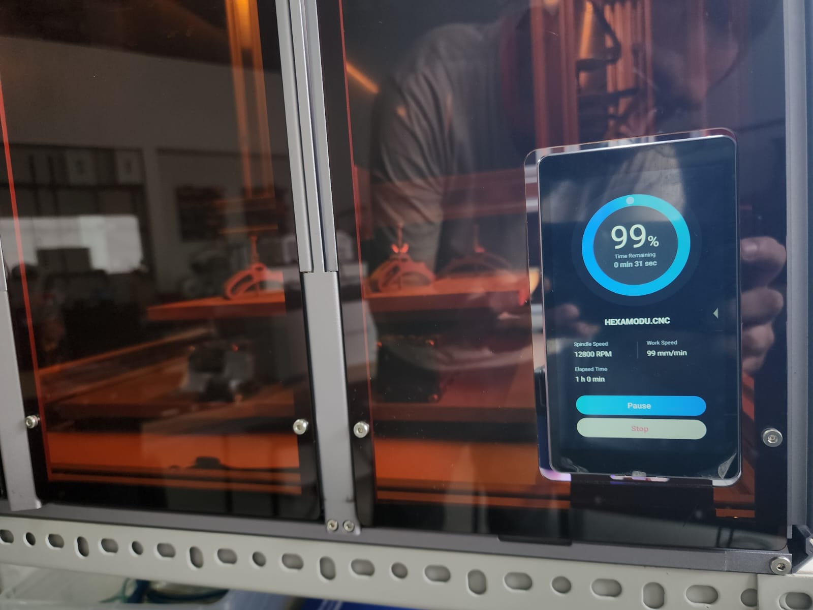
I CAME TO FABLAB U.P TO USE THEIR SNAPMAKER CNC
In record time I had to learn how to use the SNAPMAKER: place my PCB, secure it, change tools, and level the surface.
I brought my G-code and loaded it into the SNAPMAKER.
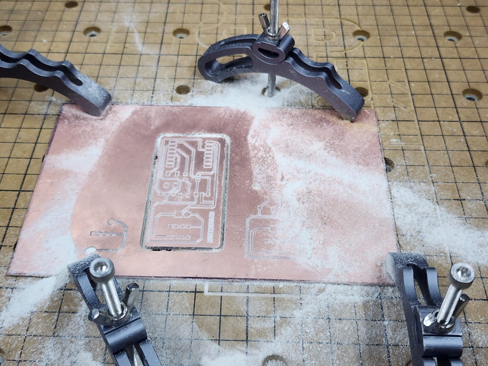
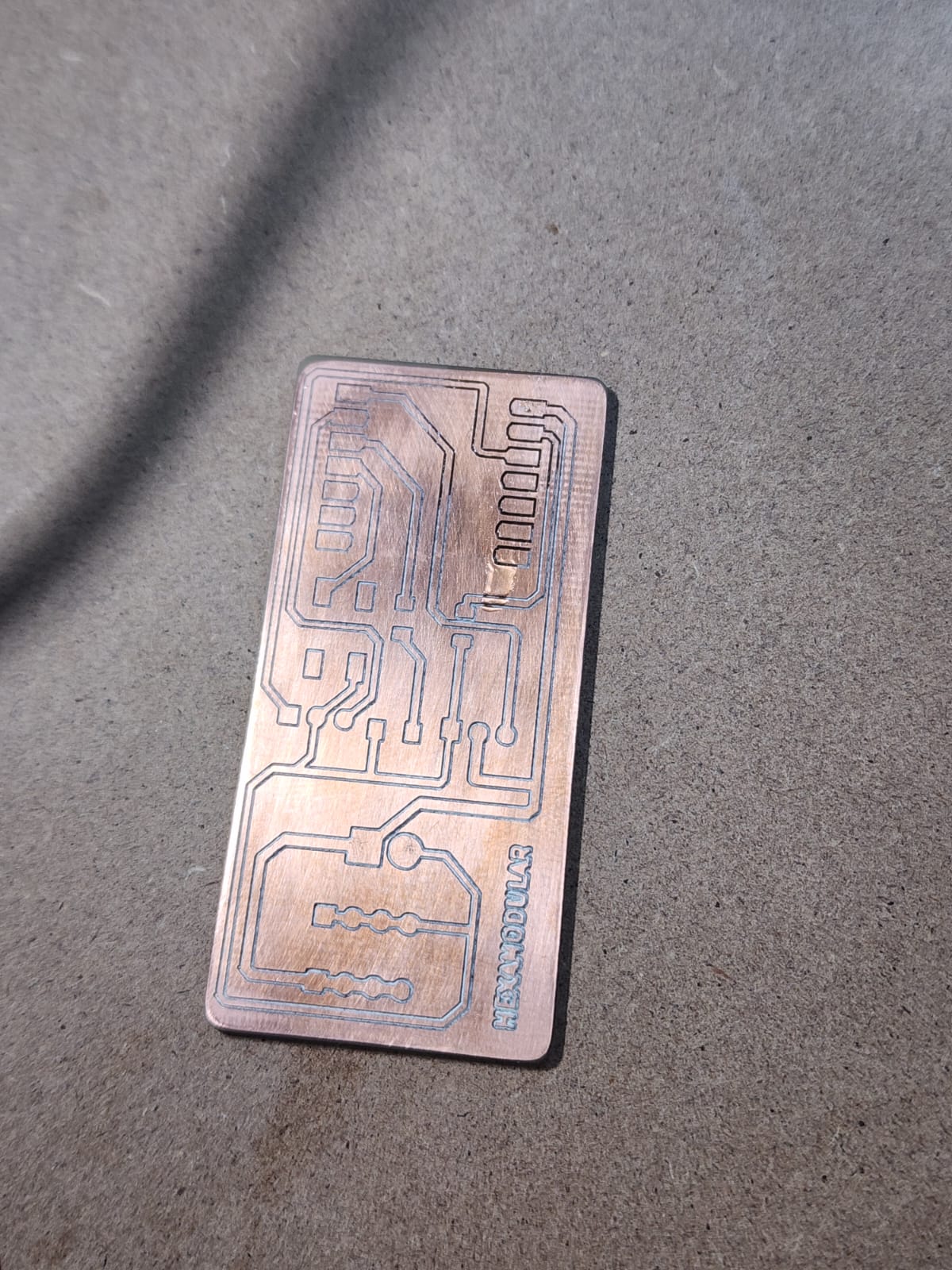
The results are good, but I think I needed more engraving spacing. The process took too long, so I think I will do it with laser engraving instead.... XDDDD
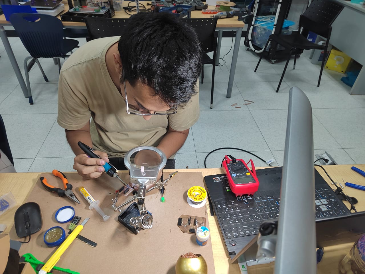
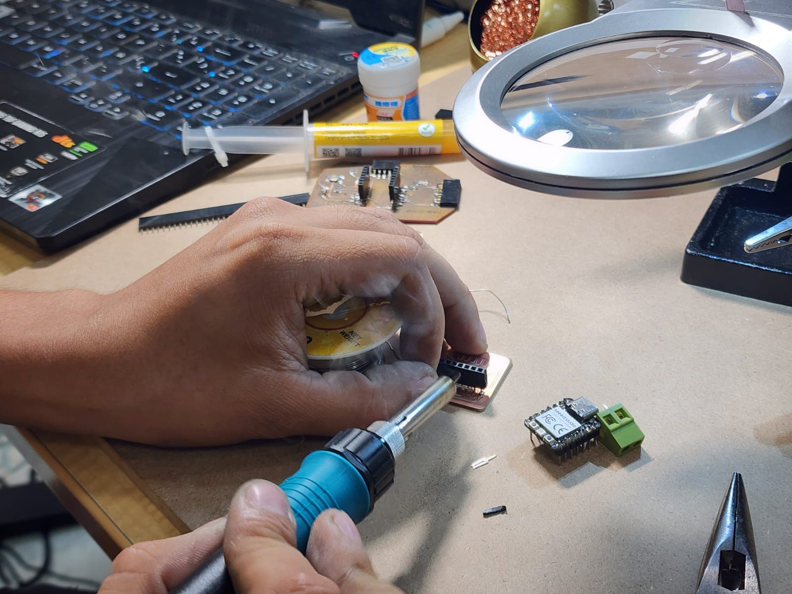
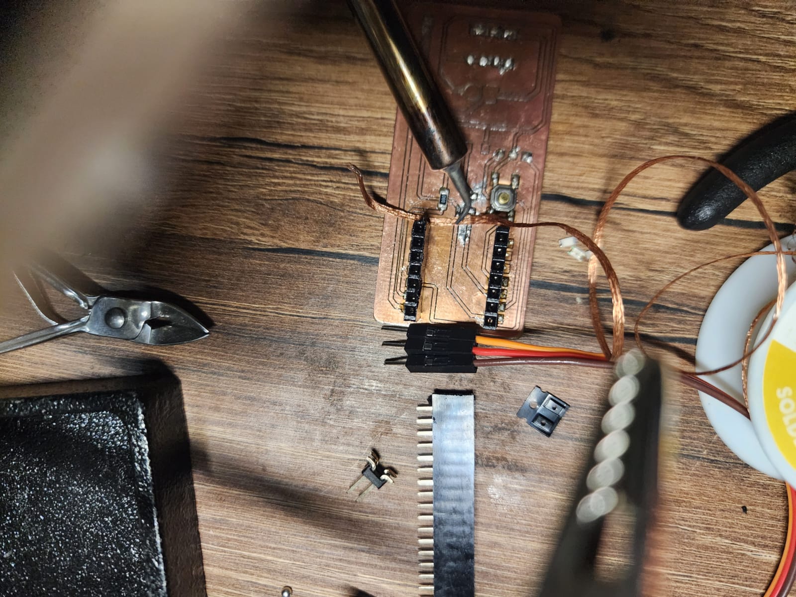
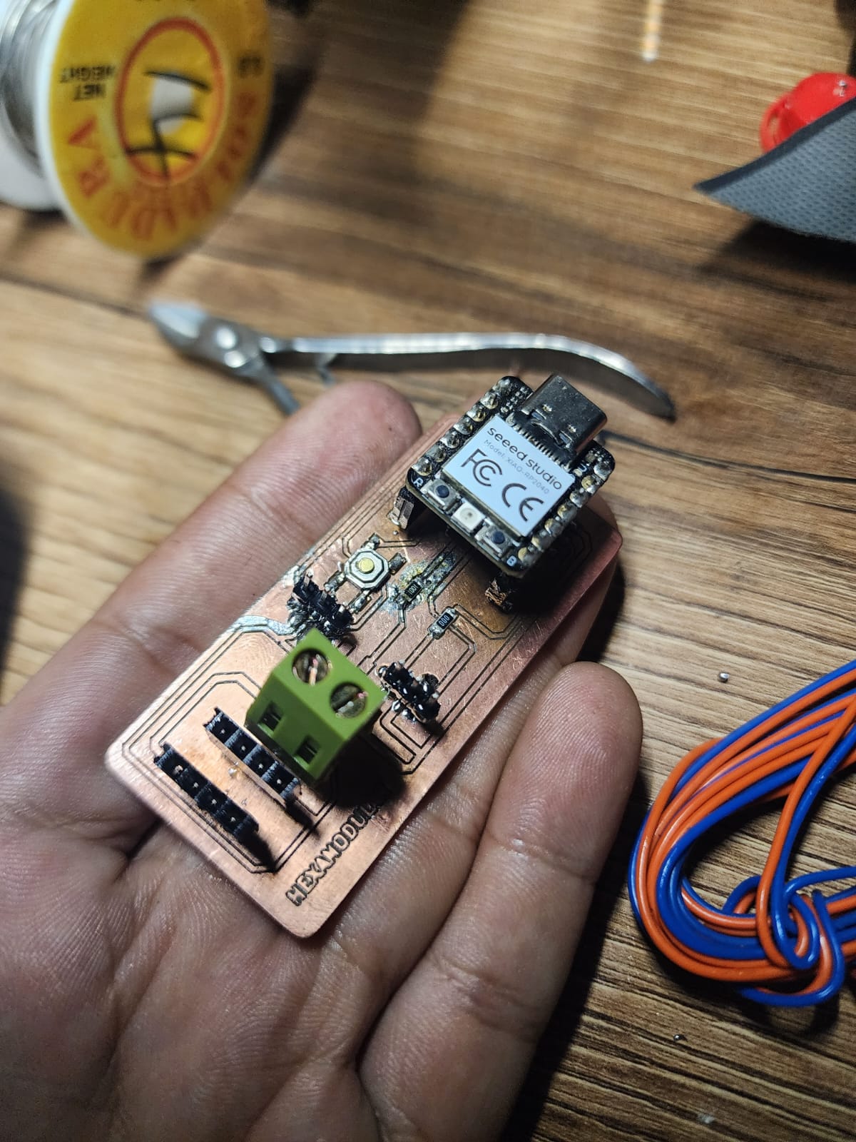
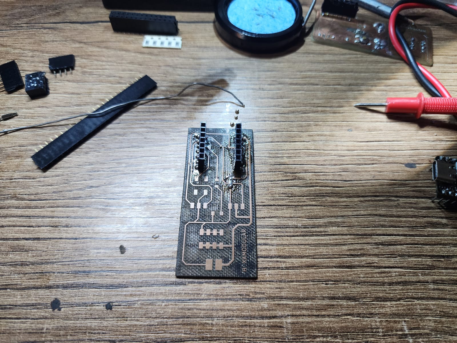
SOLDERING IS NOT MY THING!! XD
The socket for the XIAO was easy for me to solder. Everything was fine up to that point... but the ending was F.
WOW, soldering on a full copper board is complicated. I think it is necessary to remove everything that is not part of the traces.
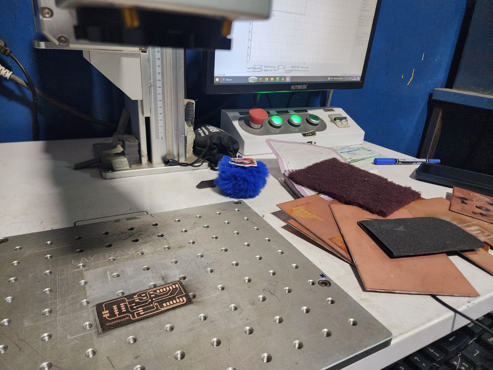
I BETTER MAKE MY PCB WITH LASER ENGRAVING
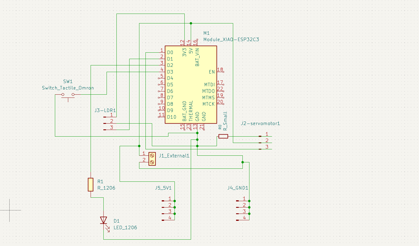
This is the final schematic with which I will make my laser PCB, a button and LED were added in relation to week 6 of "Electronics Design"
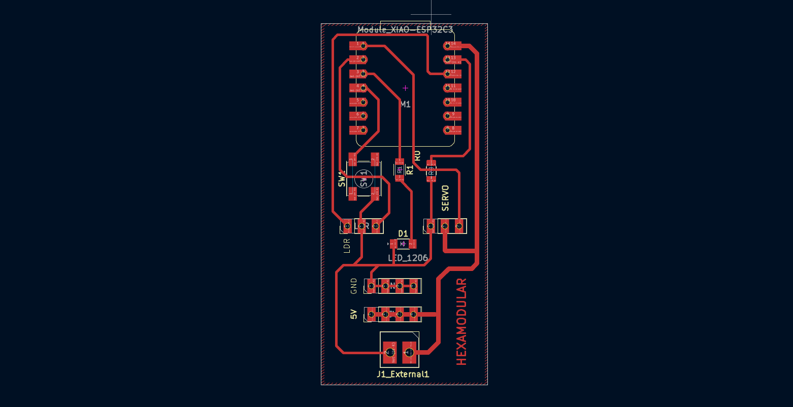
This is how my PCB design would look, with the traces and cuts for the laser. The position of the external power connectors was also changed.
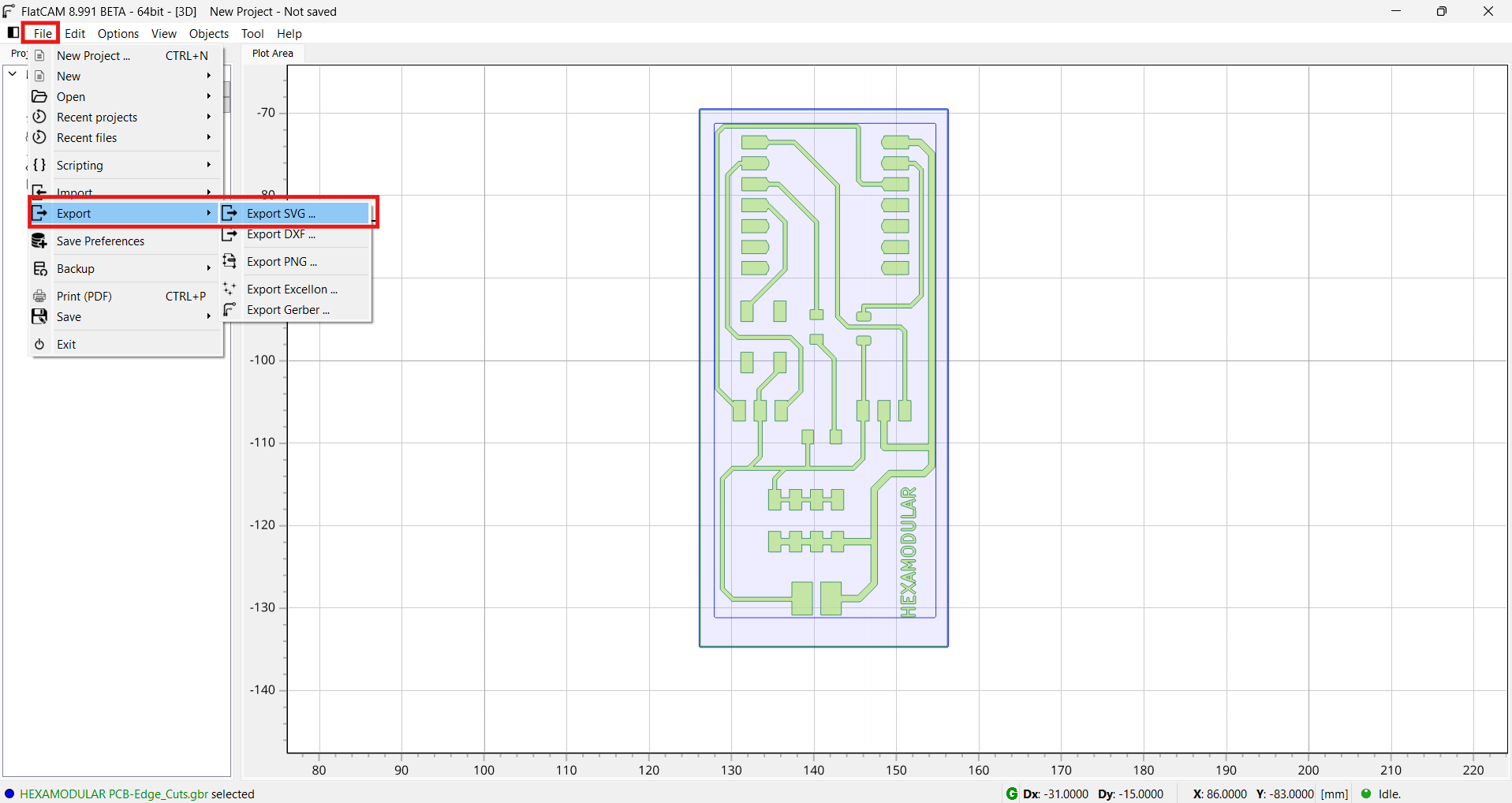
With FlatCAM already open from the previous step, we now export our design in SVG format.
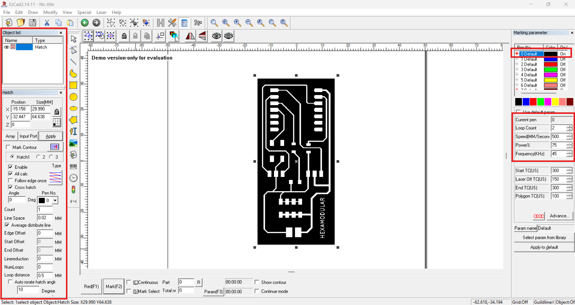
We import the SVG of our board into the EZCAD2 software to engrave it with the laser. We set the hatch to cross pattern and use the following parameters: 500 mm/s speed, 70% power, and 45 kHz frequency in 2 passes.
Wowww...que facil se me hace soldar asi!!! XD
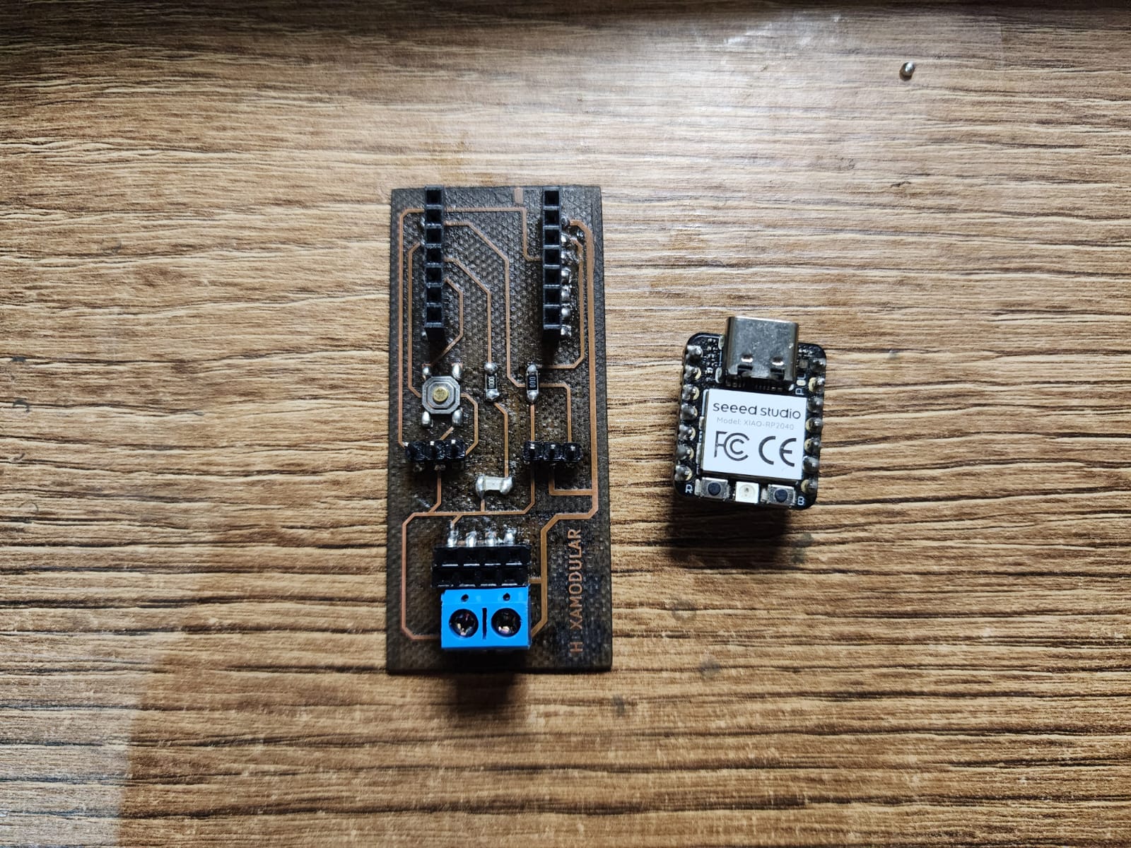
The PCB was tested with the XIAO RP2040, turning on the LED with the button. Below is the code and video.
Conclusions:
We opened the GERBER file previously saved from KiCad and positioned it at positive origin coordinates.
What impressed me was its height-map calibration for PCB boards, performing Z probing across the entire work area.

// Pin definitions
const int pinLED = D2;    // Pin where the LED is connected
const int pinBoton = D3; // Pin where the button is connected

void setup() {
  // Configure the LED pin as output
  pinMode(pinLED, OUTPUT);

  // Configure the button pin as input with internal PULLUP resistor
  // This prevents the pin from "floating" and detects a 0 (LOW) when pressed
  pinMode(pinBoton, INPUT_PULLUP);
}

void loop() {
  // Read the button state
  int estadoBoton = digitalRead(pinBoton);

  // Since we use INPUT_PULLUP, the state will be LOW when pressed
  if (estadoBoton == LOW) {
    digitalWrite(pinLED, HIGH); // Turn the LED ON
  } else {
    digitalWrite(pinLED, LOW);  // Turn the LED OFF
  }
}
FILES