WEEK 02
Computer-Aided Design
ASSIGNMENTS
° Model (raster, vector, 2D, 3D, render, animate, simulate, ...) a possible final project, compress your images and videos, and post a description with your design files on your class page.
2D raster design refers to any type of digital image represented through a grid of pixels. A pixel is the smallest unit of color that makes up a digital image. In bitmap images, the visual space is divided into regular cells, where each cell represents a single color value.
We will download and install the program, either the trial version or by purchasing it here: Abobe Photoshop
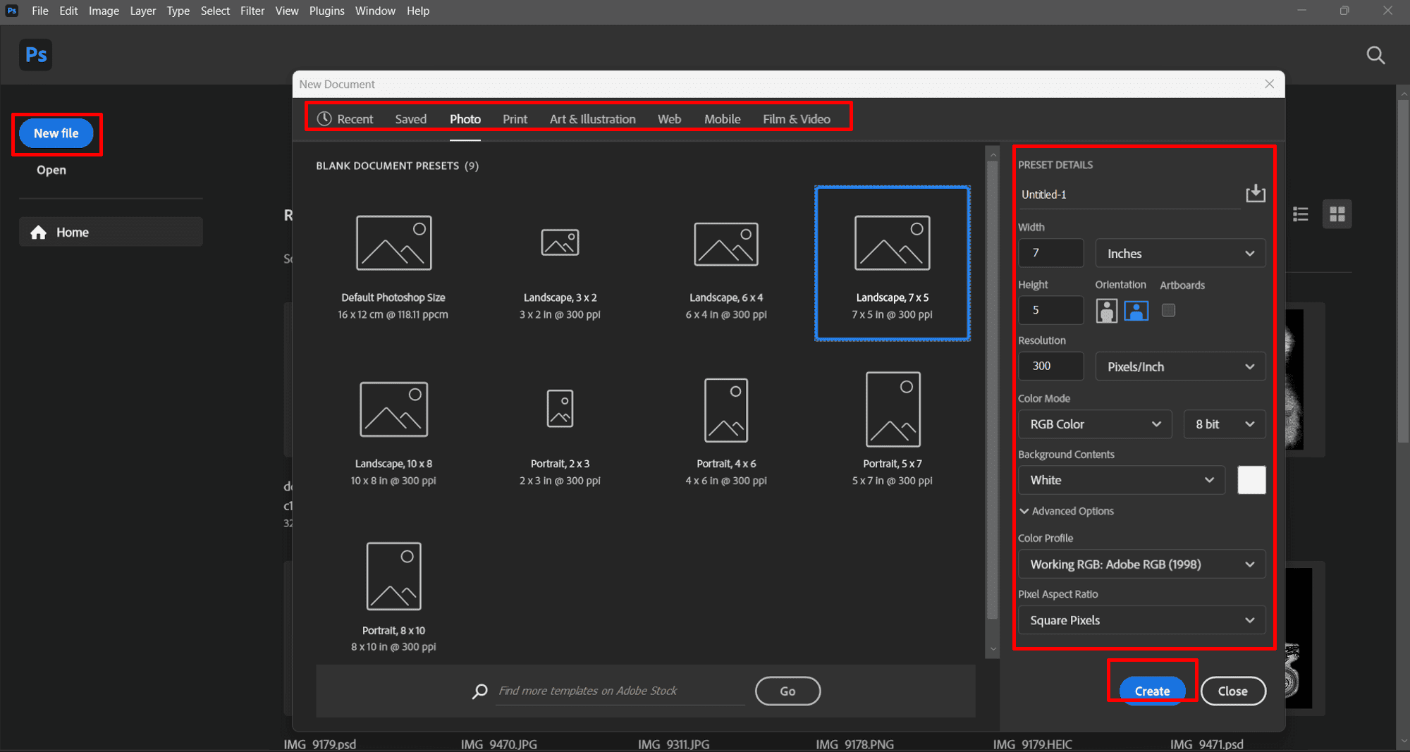
When we create a new file by clicking on the "New File" tab, the configuration and preset settings window will appear. In this case, I chose the "Landscape, 7x5" working format at 300 ppi (which refers to the size and resolution) from the "Photo" tab, for this example. I left the other settings at their defaults.
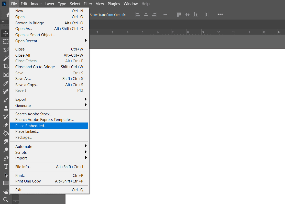
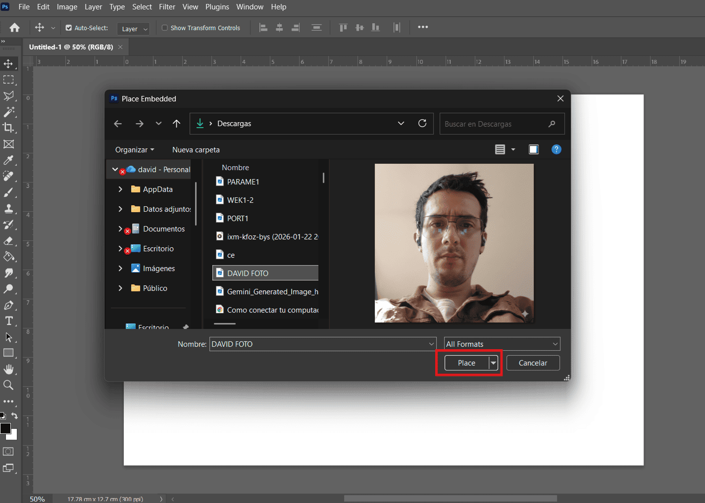
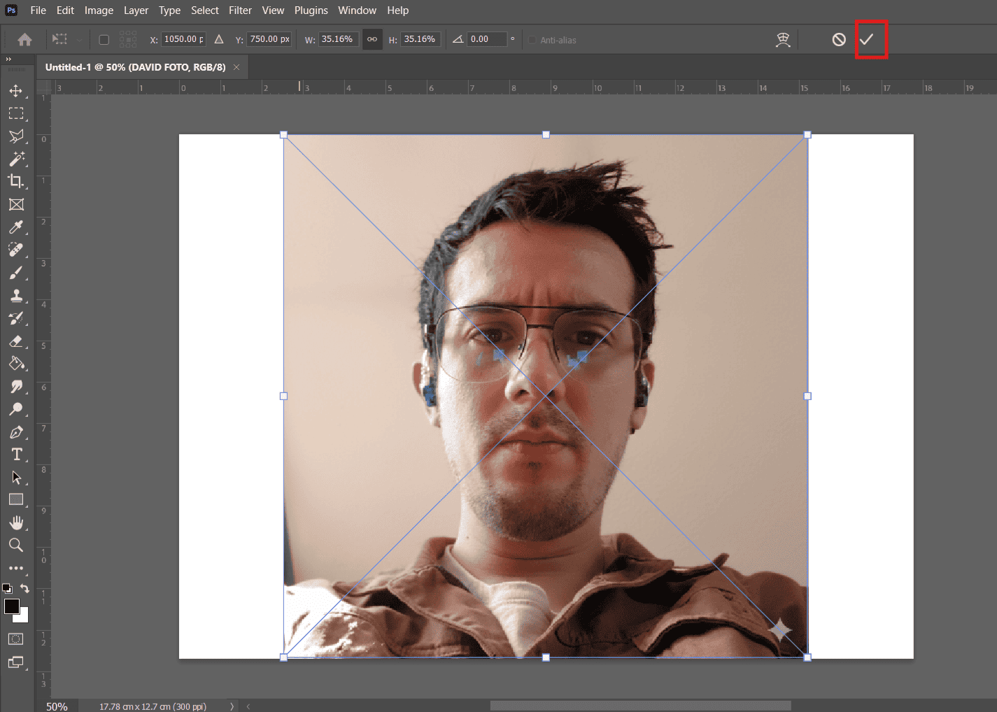
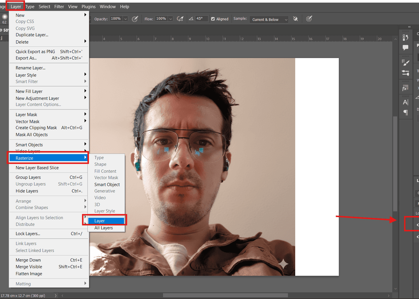
We click on "Place Embedded" to insert an image into our document. We choose the photo to insert from our computer. We resize and position the image, then click the check mark. We click on the "Layer" tab, then go to "Rasterize" and choose "Layer" to convert the image into an editable format.
Explore commands such as the elipse tool (to generate a perfect circle, hold down the Shift key) and the text tool (we can change the size in the properties bar); when executed, they are generated in individual layers as shown in the layers bar located on the right side.
GIMP is 100% free and open source. Download it here:GIMP
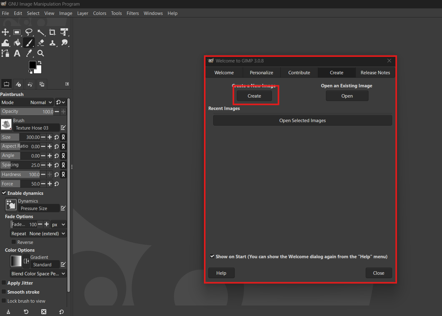
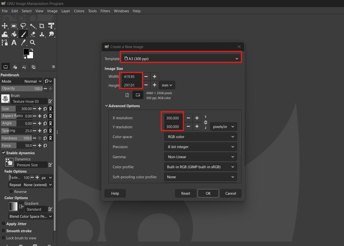
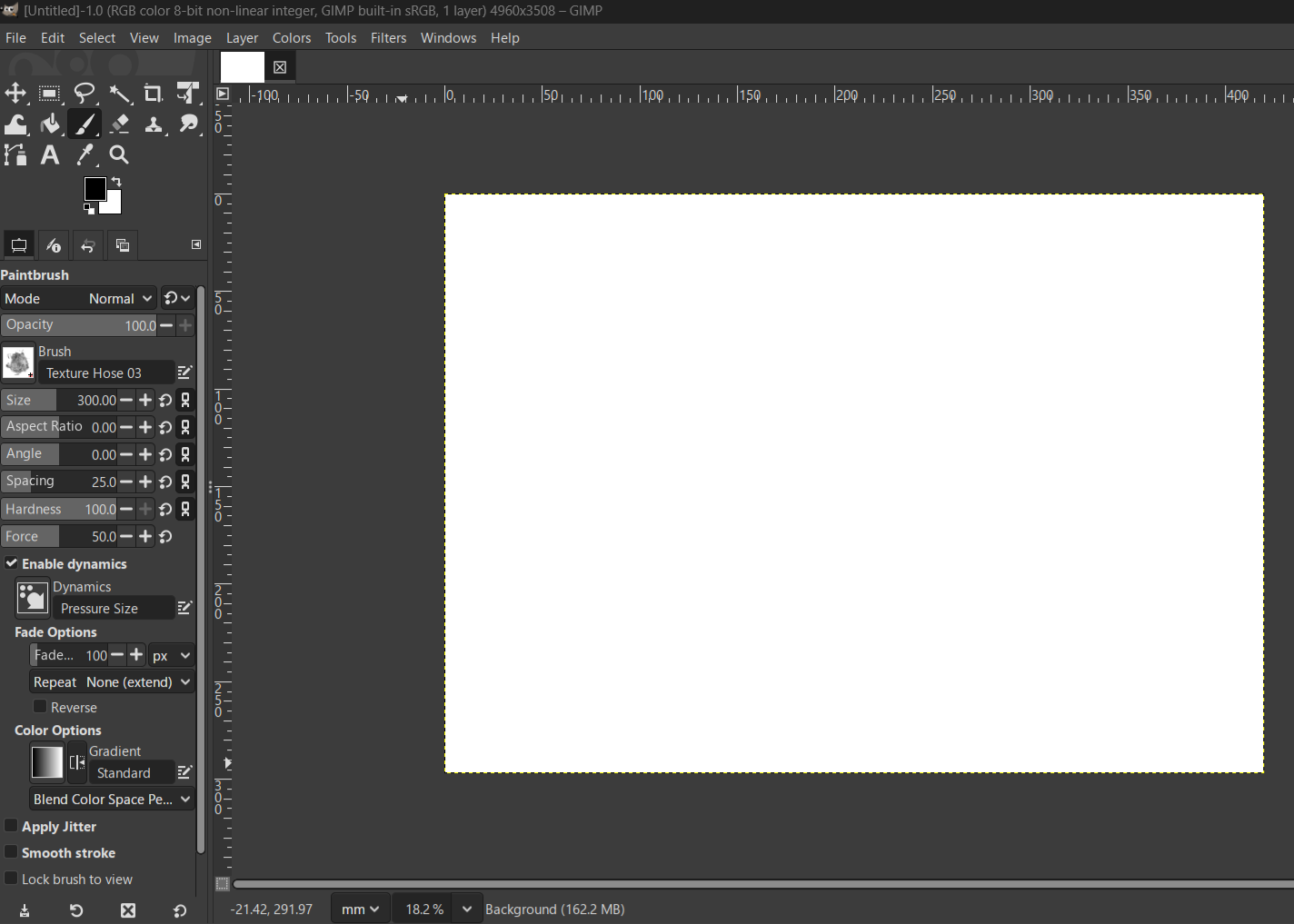
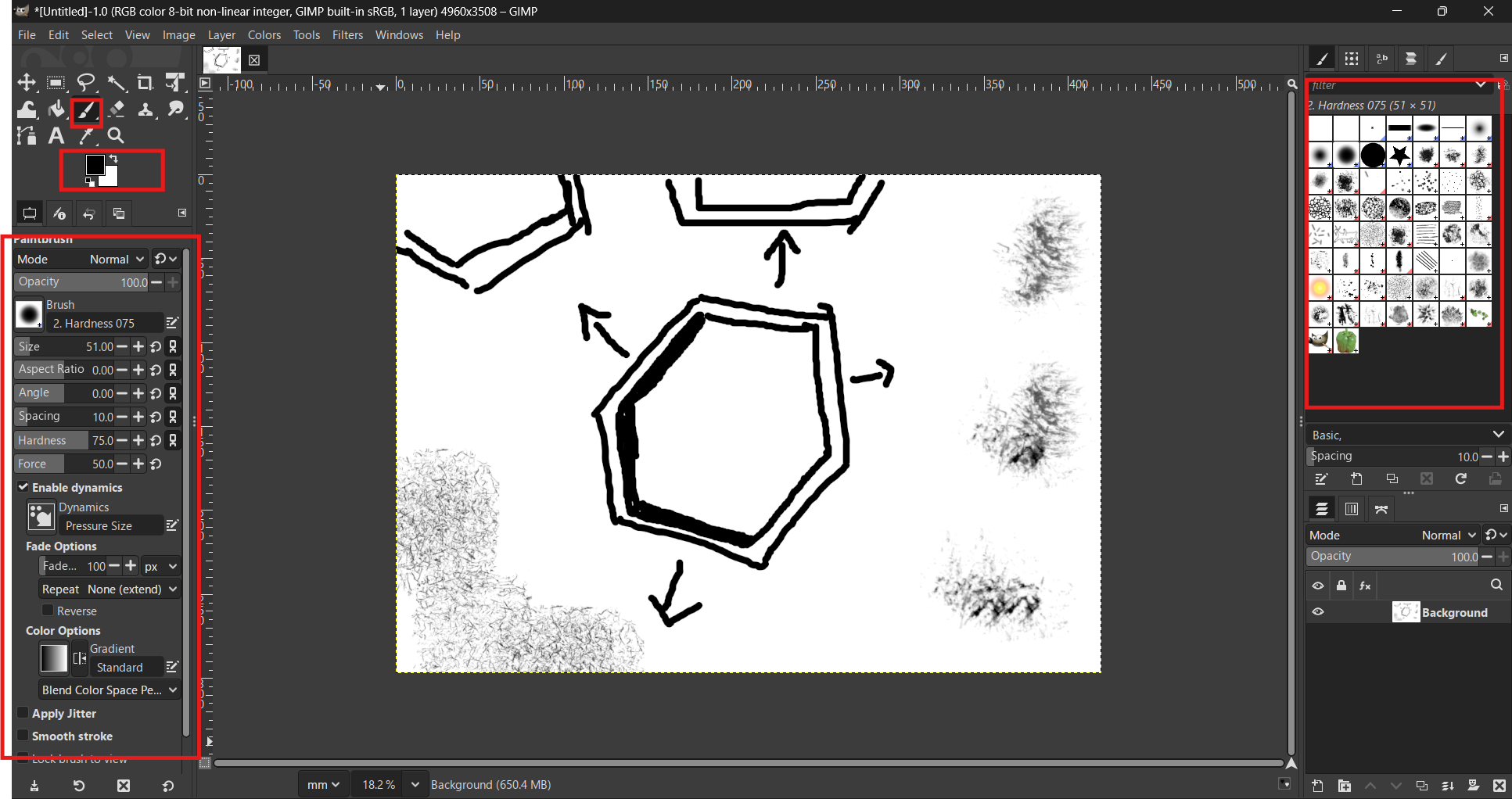
Opening GIMP and setting up the workspace. We configure the document settings, such as resolution and size. Now we can start drawing.
In this section, I am documenting additional processes and relevant screenshots of my work during this week.Testing brushes,colors
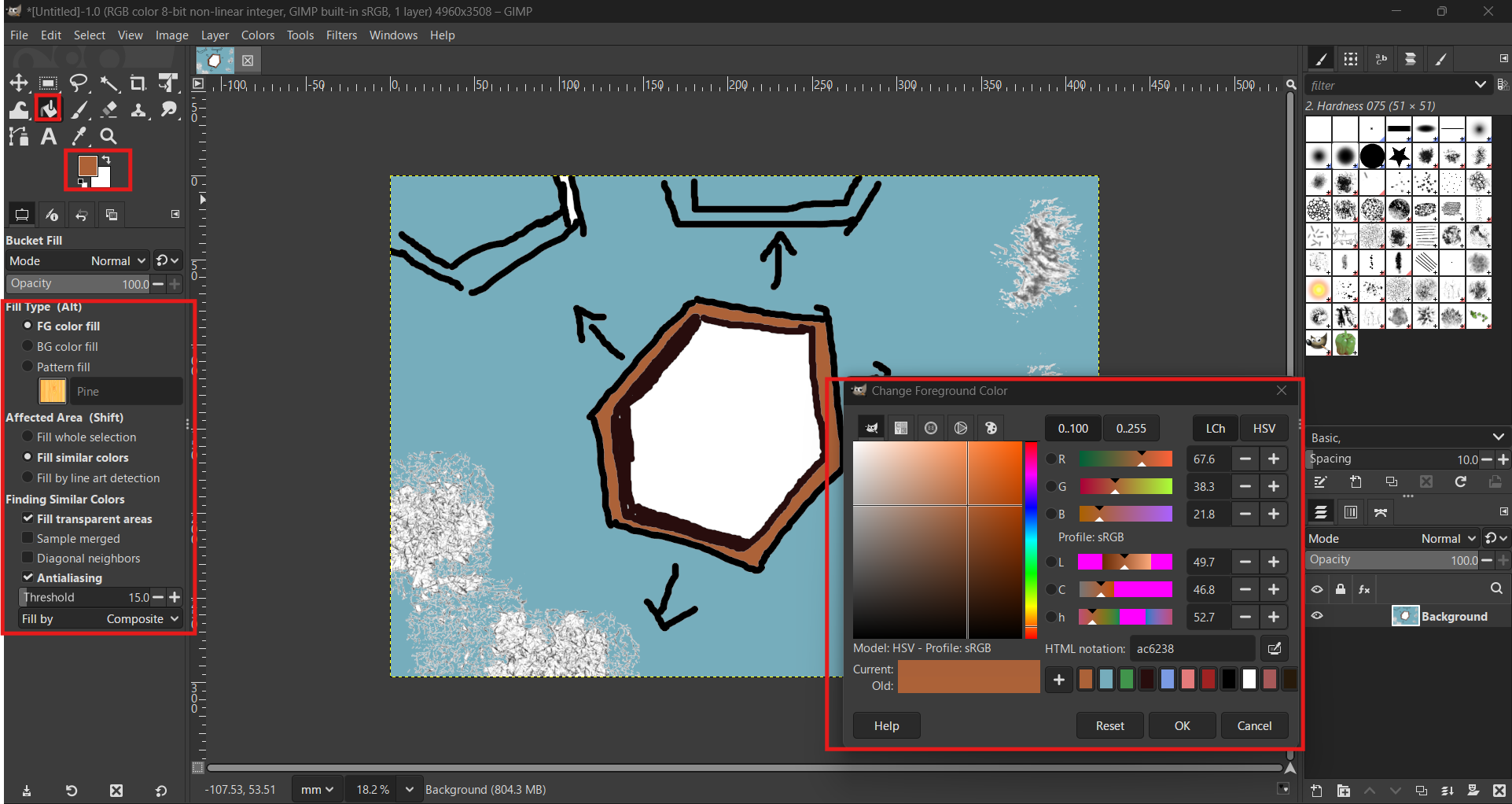
We select the brush tool and begin drawing. Now we paint the drawing with the paint bucket, and we can also choose different brush styles.
Unlike raster images, 2D vector design is based on mathematical equations that define points, lines, and curves. This means that the graphics are resolution-independent, allowing them to be scaled to any size without loss of quality or pixelation. In digital manufacturing, vector files are essential because they provide the precise paths that machines like laser cutters and vinyl cutters can follow.
Autodesk is in charge of the AutoCAD license and they offer free licenses to students for 1 year: Autodesk Autocad
We set the working units by typing "UNITS". We will work in millimeters using the International System.
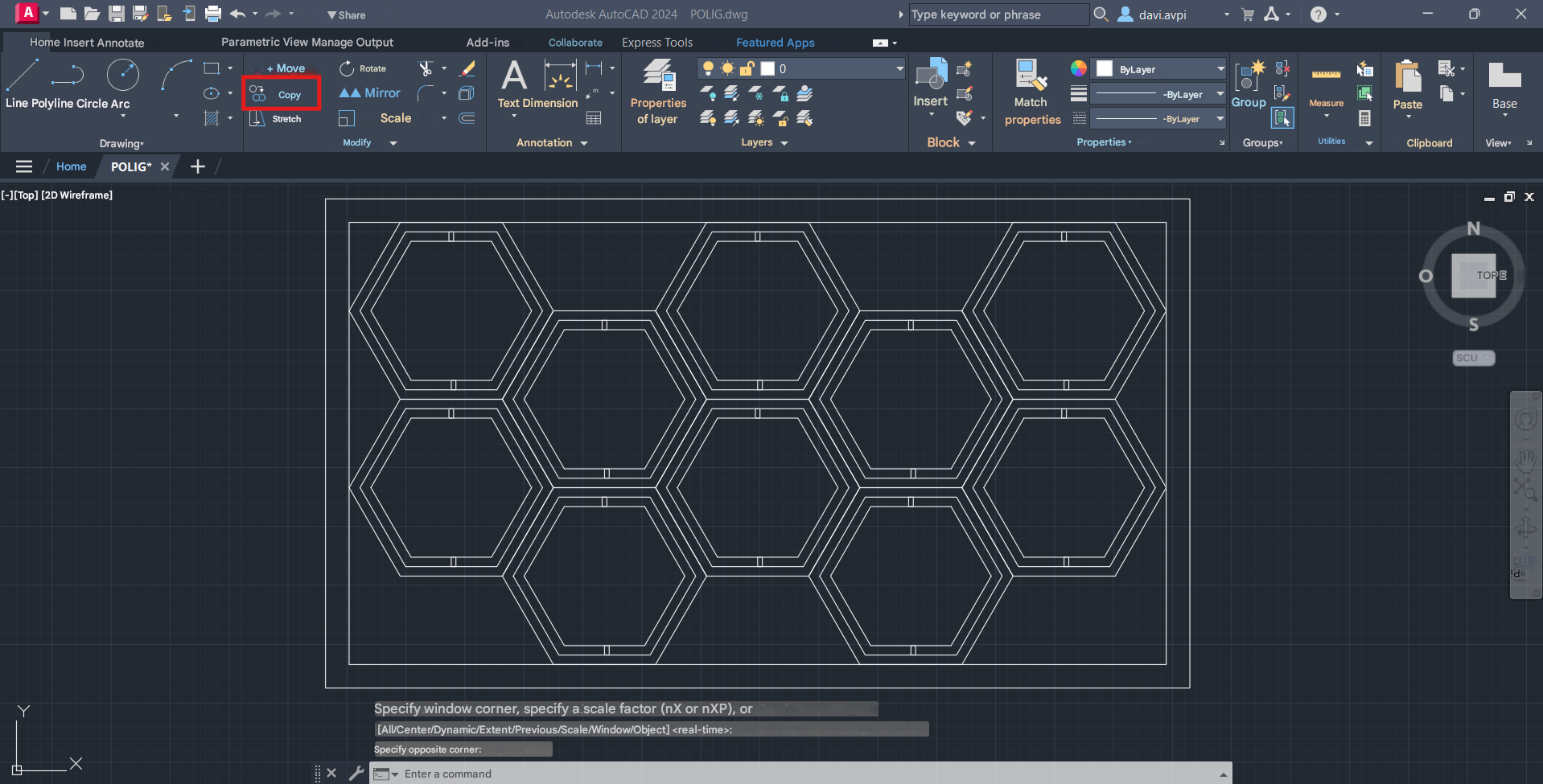
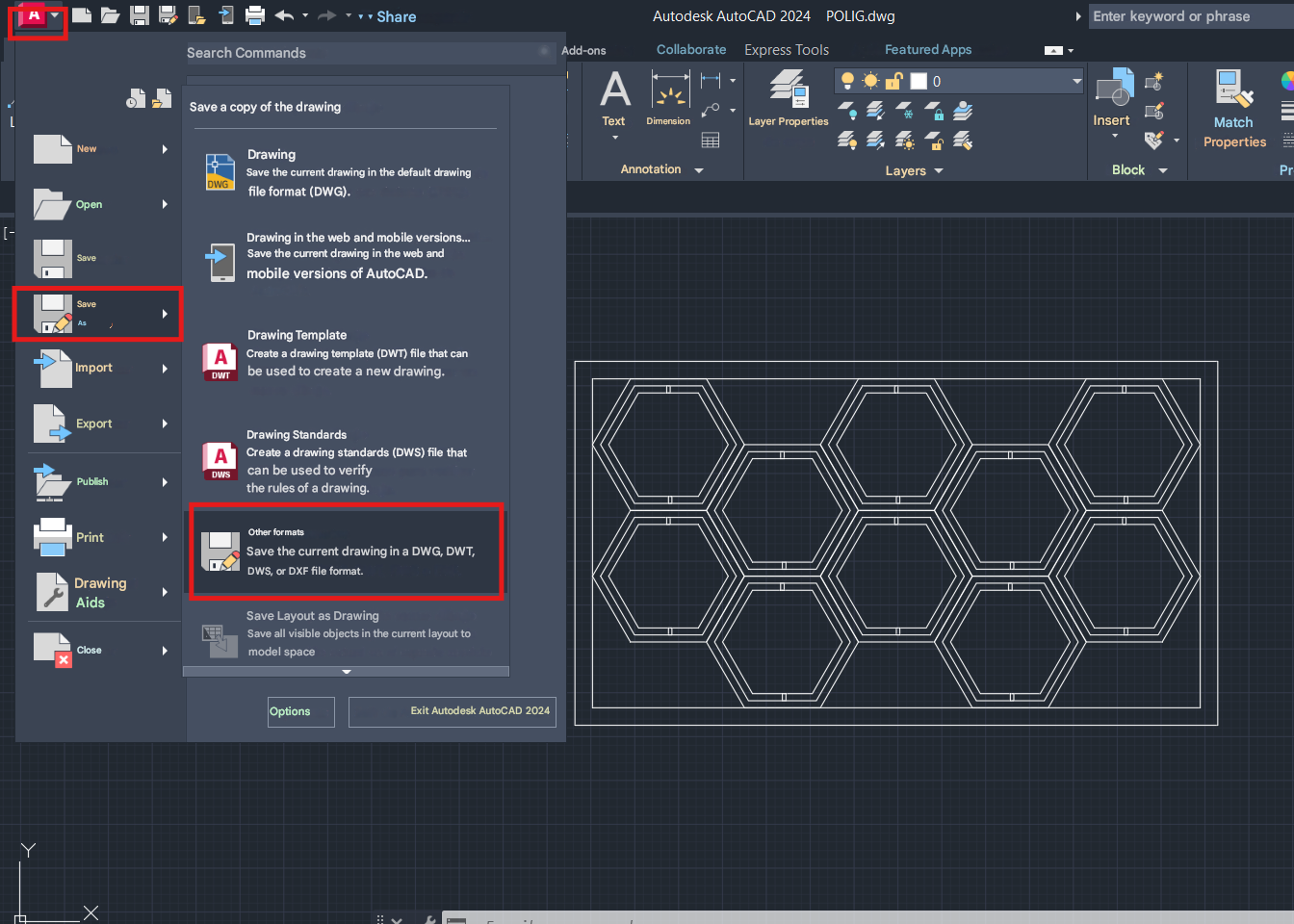
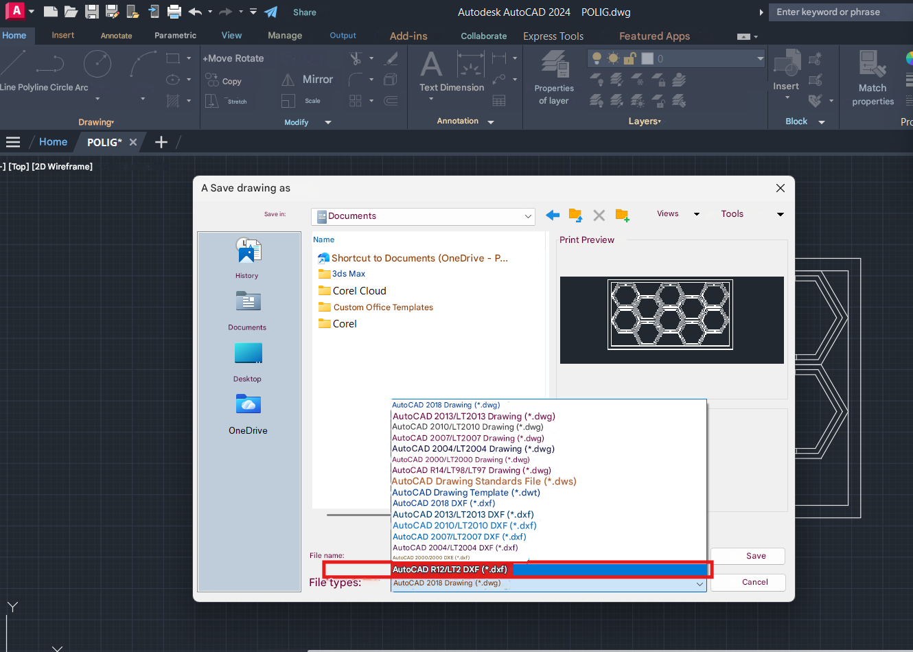
You can draw geometric shapes. In this example, I drew the basic hexagonal module using the polygon command. AutoCAD allows you to first set the exact dimensions. Afterward, you can make copies with offsets and modify the line type. We select the "polygon" command and draw a hexagon. We create an inner and outer offset using the "Offset" command. We select all the completed polygons and click "Copy" to make the needed duplicates. We click the AutoCAD icon, then select "Save" and next choose "Other Formats". Further details or the outcome of the previous step.
Corel Draw offers various types of licenses, including a trial version.: Corel Draw 2025
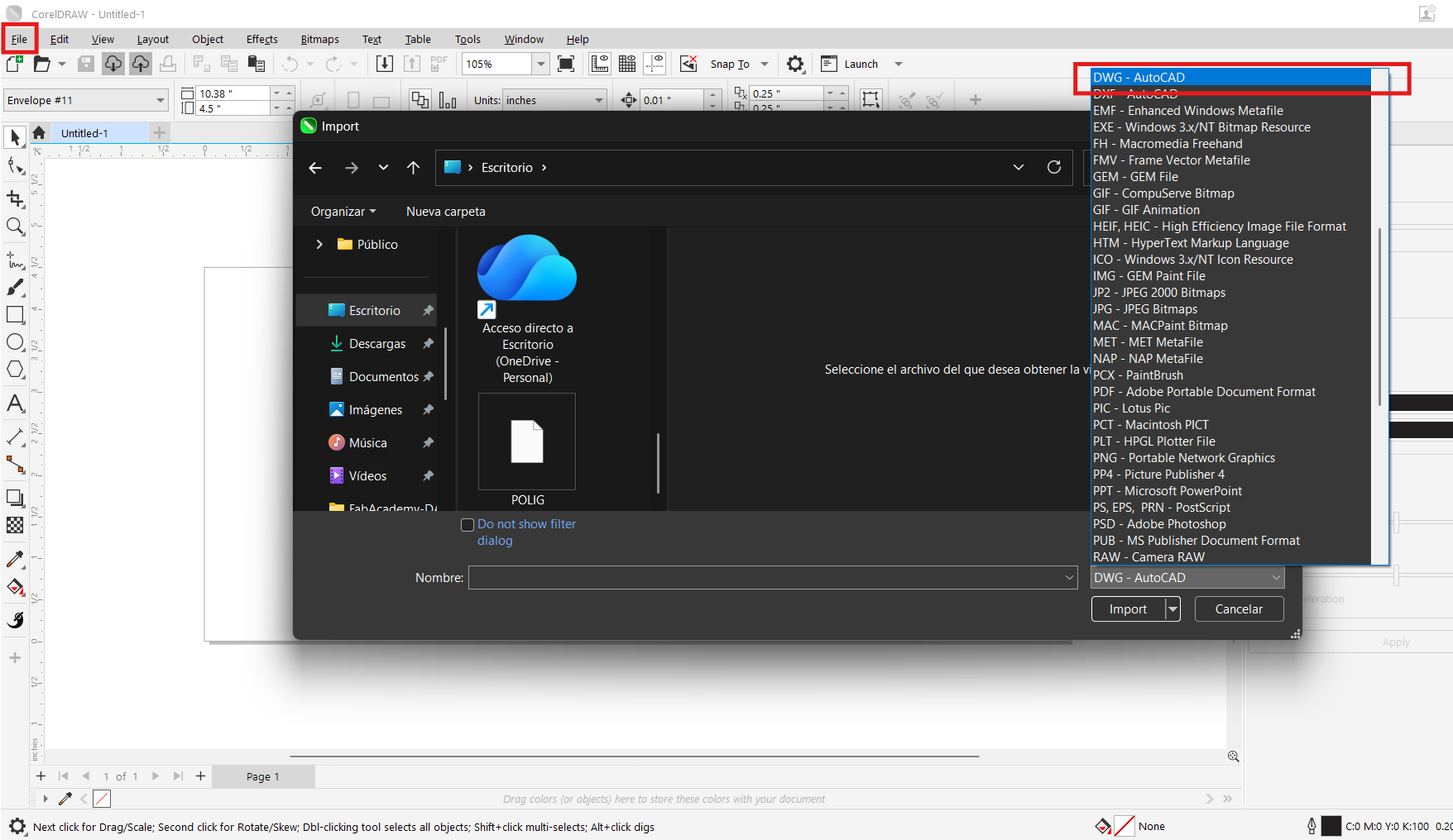
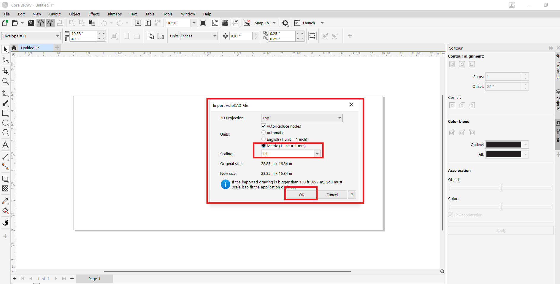
We imported the .dwg file we made in AutoCAD to explore some Corel Draw tools.
We click on file and look in the list of options for the .dwg extension of Autocad. In the window we choose the units and the actual scale. The completed 2D design ready for fabrication.
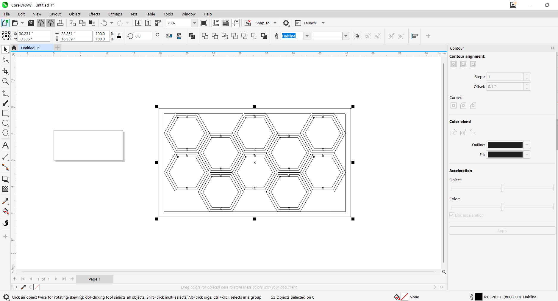
Explore adding colors to the modular panel by clicking on the smart fill tool command and modifying the colors in the command's properties bar..
There are many 3D modeling programs of mechanical, artistic, and parametric types; some are more professional, others more basic.
For this assignment, I experimented with several software tools:
Download and install the SolidWorks program, and we will use the license provided by FabAcademy:
SolidWorks
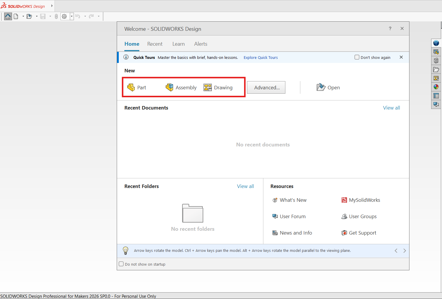
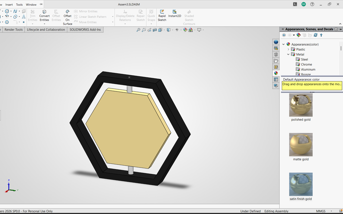
In SolidWorks, there are three types of models: the part, the assembly, and the drawing. First, I created the frame for the hexagonal module by sketching a polygon and then extruding it to give it thickness.
Then I made another piece for the movable sheet and adjusted the dimensions after correcting a measurement mistake.
The last piece was the axle that joins the parts together. In this case, I used the top plane so the position would be easier during assembly.
The assembly was somewhat complicated, since I had to create a separate assembly file, insert the parts, and apply the right constraints so the module aligned correctly.
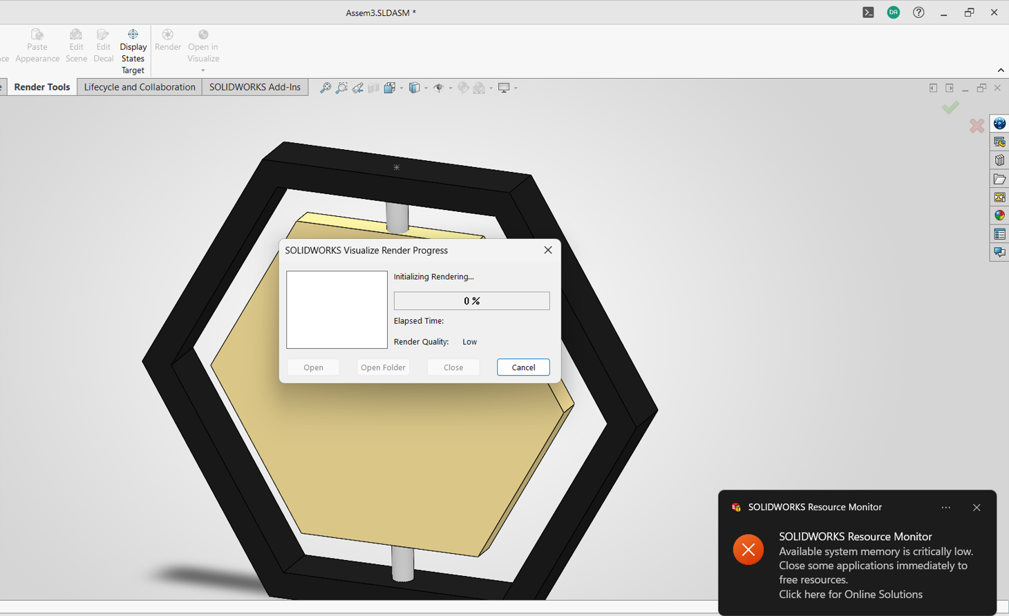
I also tried adding textures for rendering, although my laptop memory was limited and I encountered performance issues.
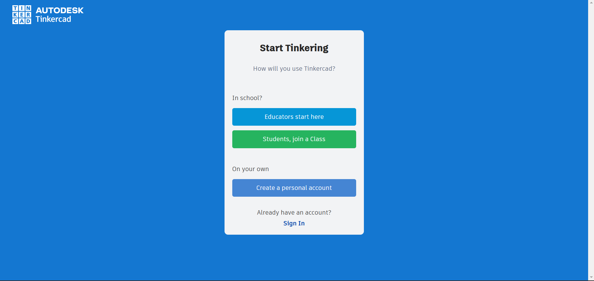
Tinkercad is an online tool developed by Autodesk that allows users to design 3D models in a simple and intuitive way. It is especially useful for beginners in areas such as digital fabrication and electronics. Through its browser-based interface, users can create, modify, and combine geometric shapes to develop prototypes, mechanical parts, or creative projects without needing to install additional software.
Open the platform here and sign in:
Tinkercad
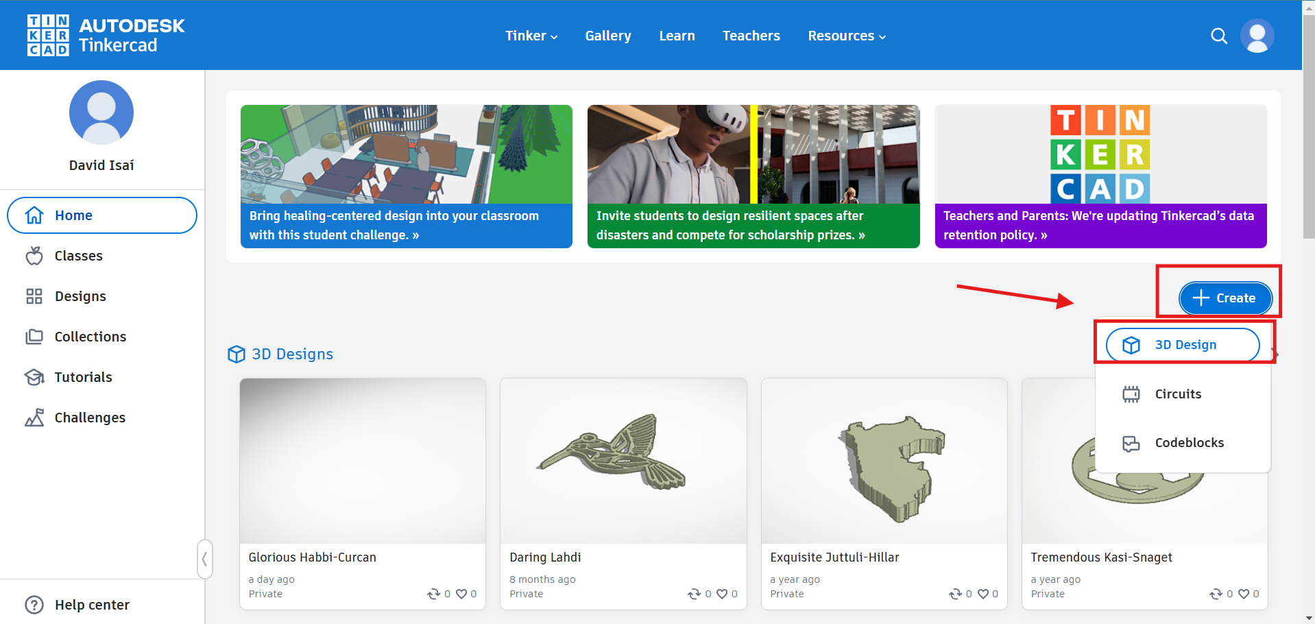
We click on "+Create" and then choose the "3D Design" option to start a new 3D design project.
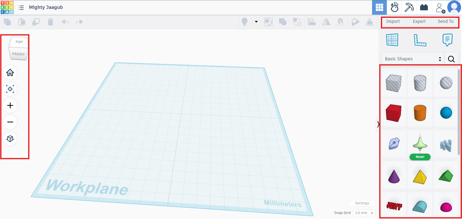
We can see the workspace interface: on the left are the viewing controls, on the right are the basic shapes used to create the model, and at the top are the editing and saving options.
We choose the cylinder shape as an example and insert it by clicking on it.
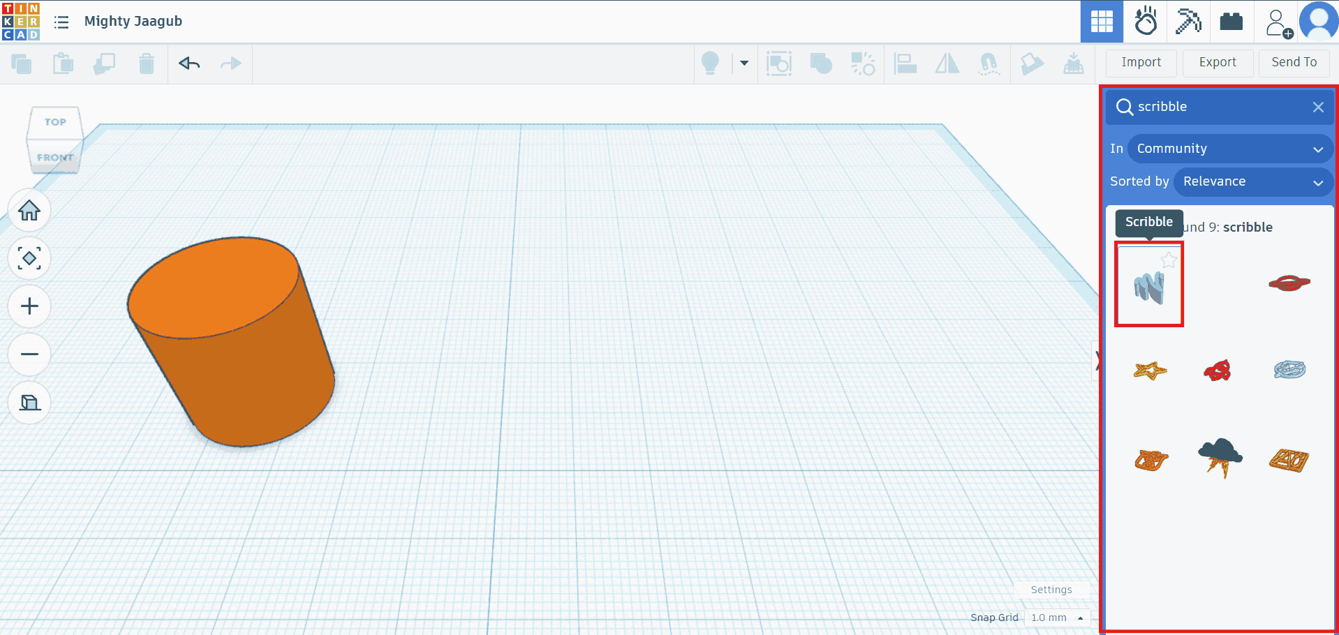
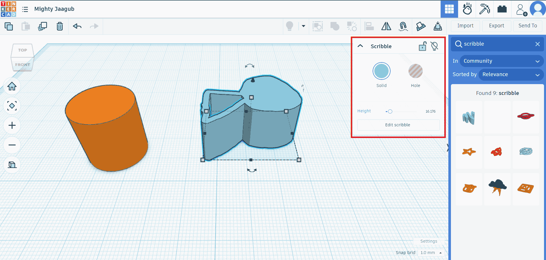
Now we will look for the "scribble" command to draw freehand.
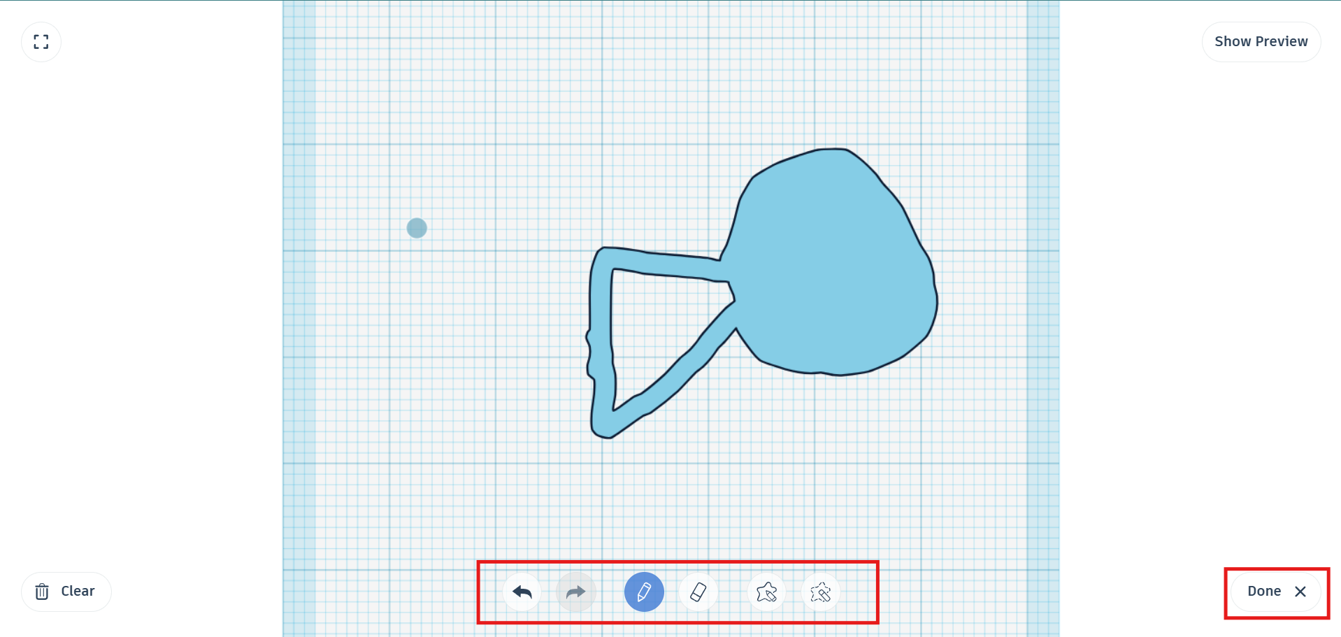
We draw something freehand, then the top view opens and the drawing options appear at the bottom,
We can draw something using the pencil icon, and we can also erase or fill areas by passing the pencil over them several times. Then we can edit the color and height to create the 3D model.
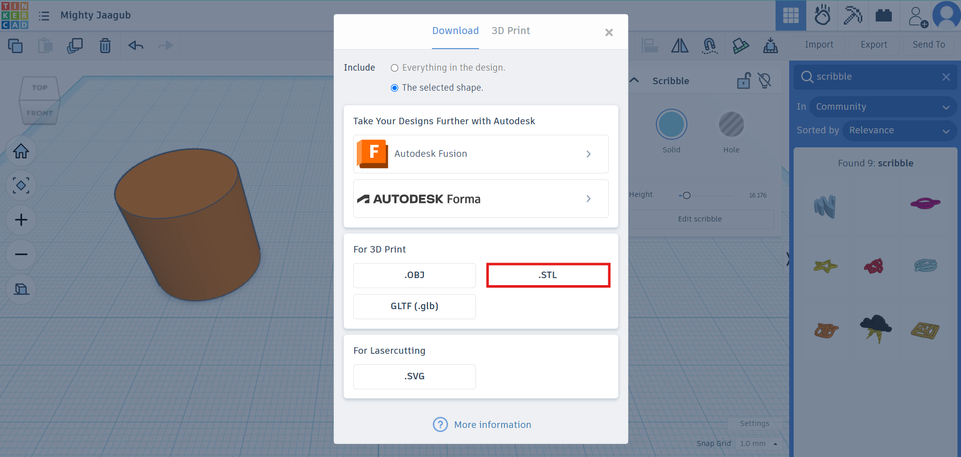
Finally, we can export or save the file in different ways; in this case, I chose to export it as `.STL`.
PROMPT:
Generate a photorealistic image from the attached photo, giving the gold a shiny texture. Make the middle hexagon rotate only slightly.
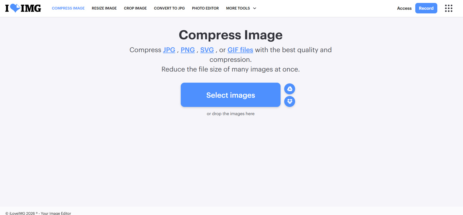
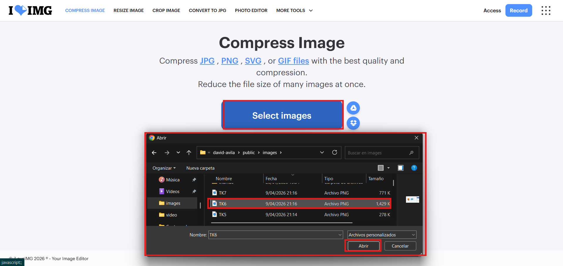
I used ILOVEIMG to compress images and keep the page lightweight without losing too much visual quality.
Then we click "Select images" to upload the images we want to compress.
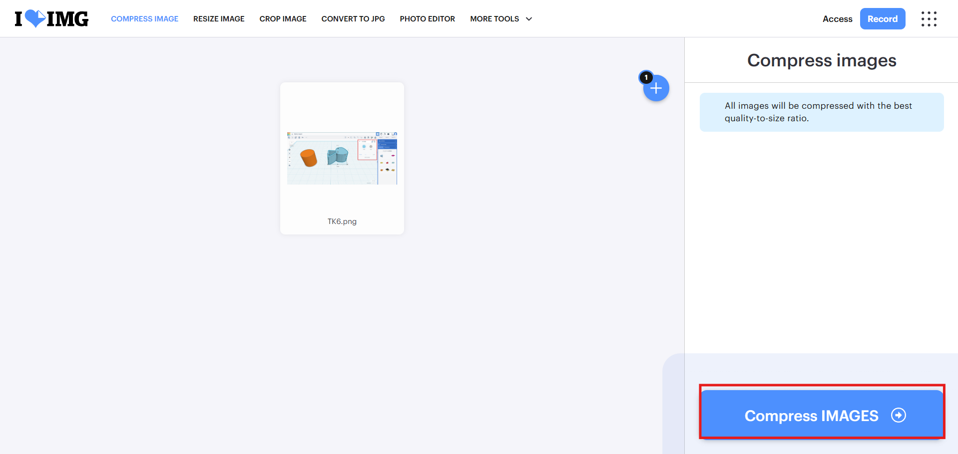
After that, we click "Compress images" to start the compression process.
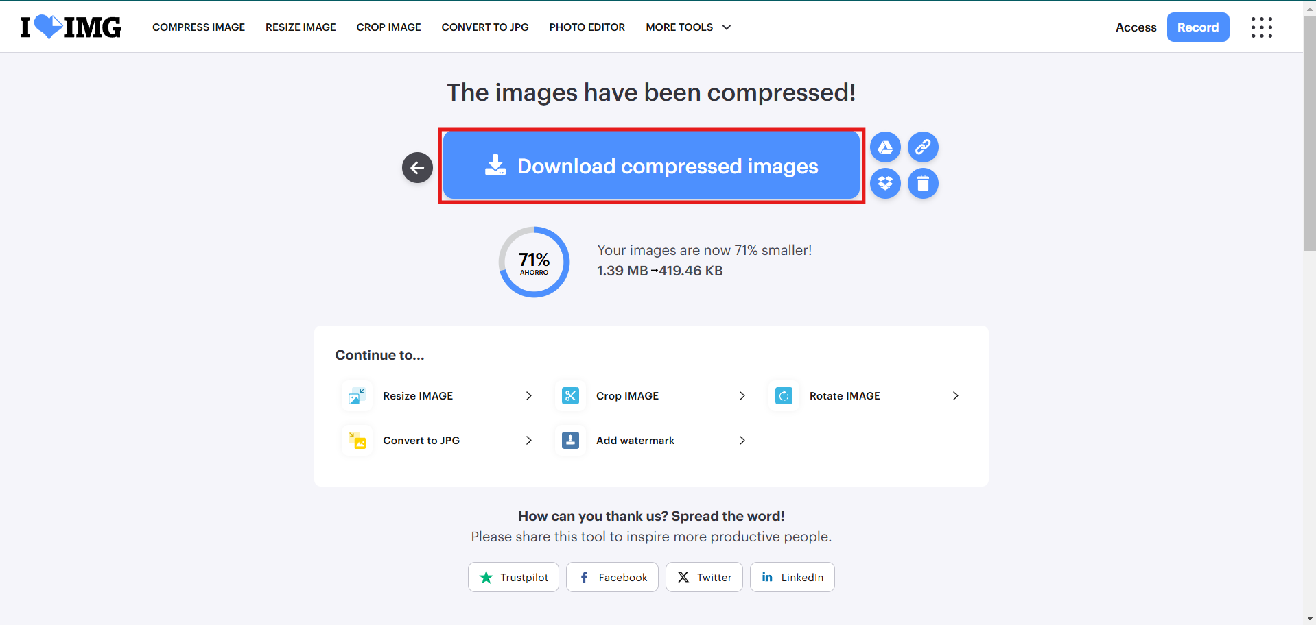
Finally, we download the compressed images and save them in the project folder to use them on the website. Done!
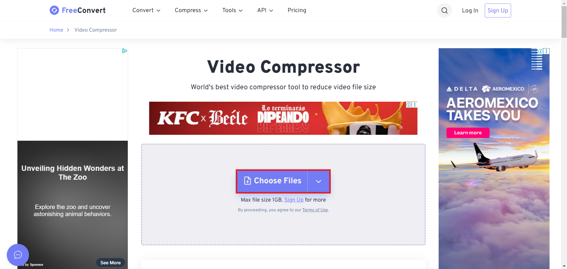
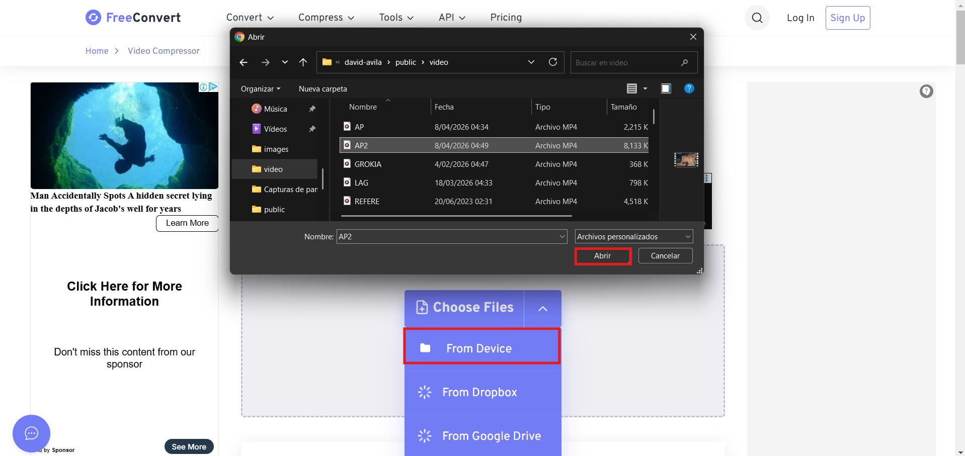
FreeConvert is a free website for compressing videos, with some limits such as a maximum size of 1 GB and certain output formats, but it works well for this academy project.
Then we click "Choose Files", browse for the video we want to compress on our device, and select it.
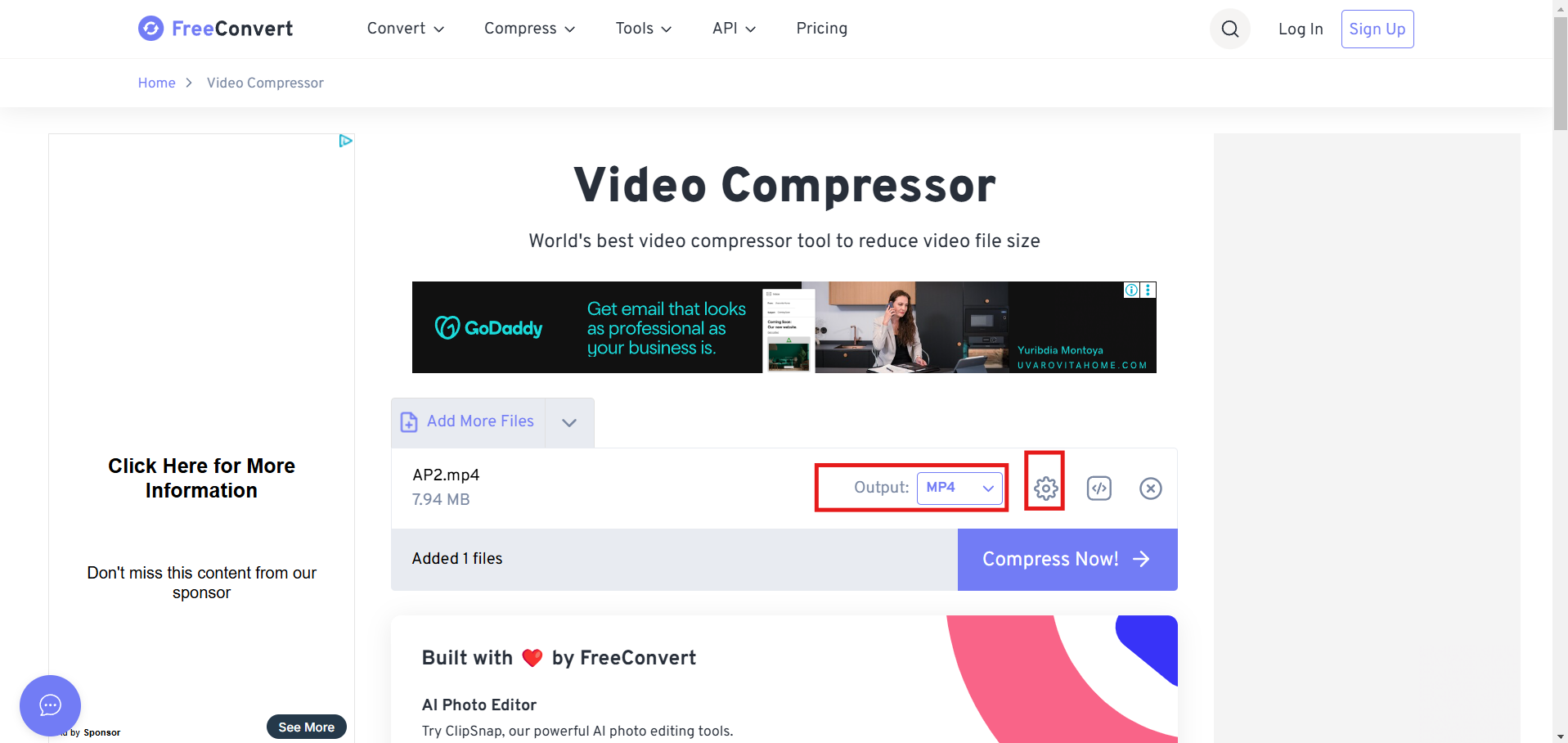
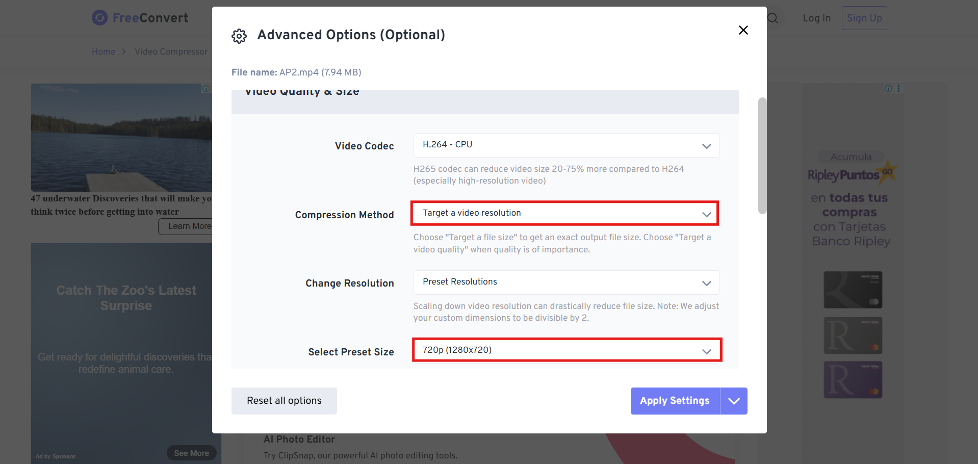
After that, we configure the compression options, such as output format, quality, and the size of the compressed video.
We click the settings button. We proceed to configure and apply the compression options.
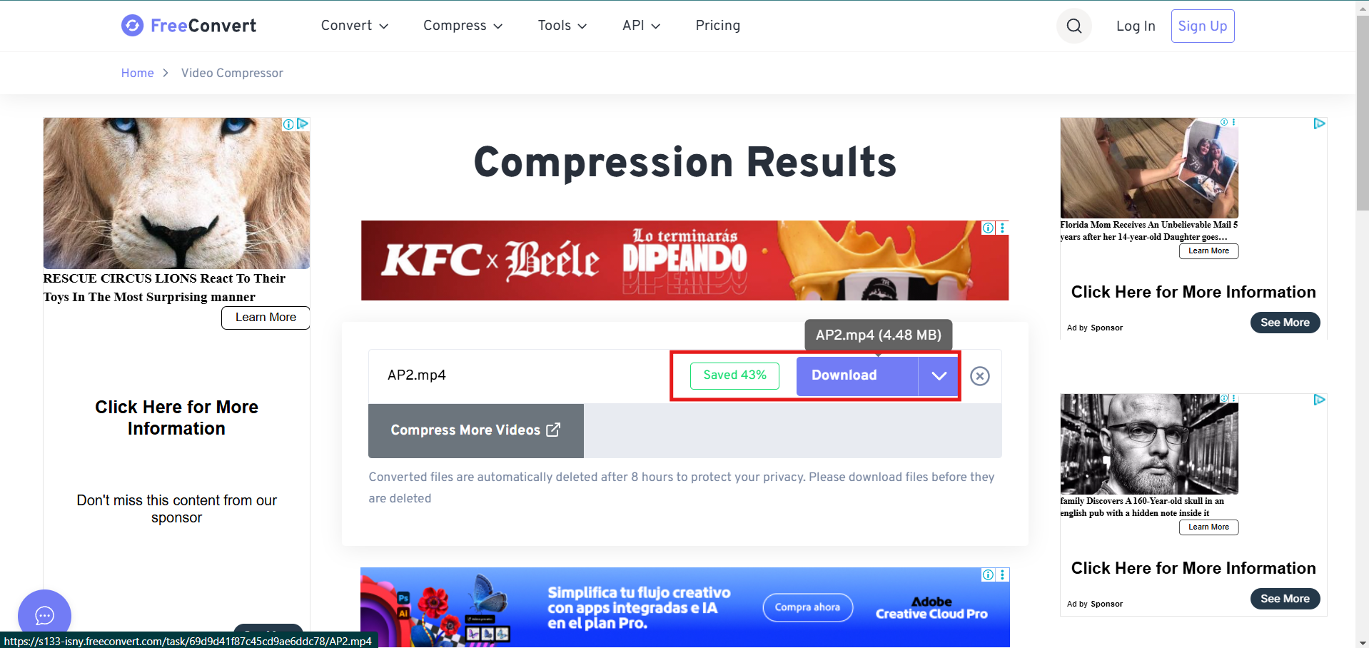
Finally, we wait for the compression to finish and click "Download" to get the compressed video.
2D Design -Raster
For this assignment, I experimented with several software tools:

ADOBE PHOTOSHOP
Inserting an image for editing:
Step 1
Step 2
Step 3
Step 4
When you zoom in all the way at the end, you can see the pixels as small colored squares due to the objects you have inserted.

GIMP - GNU Image Manipulation Program
Creating a worksheet is very similar to the previous program. It has a similar configuration, but the interface is different because the command options are displayed first.
Step 1
Step 2
Step 3
Additional Process 1
Additional Process 2
2D Design - Vector
For this assignment, I experimented with several software tools:
AUTOCAD 2D
AutoCAD is software used by architects and engineers because of its professional-level interface for drawing plans. In my case, I always create a template in ISO configuration because it is the metric system used in my country.
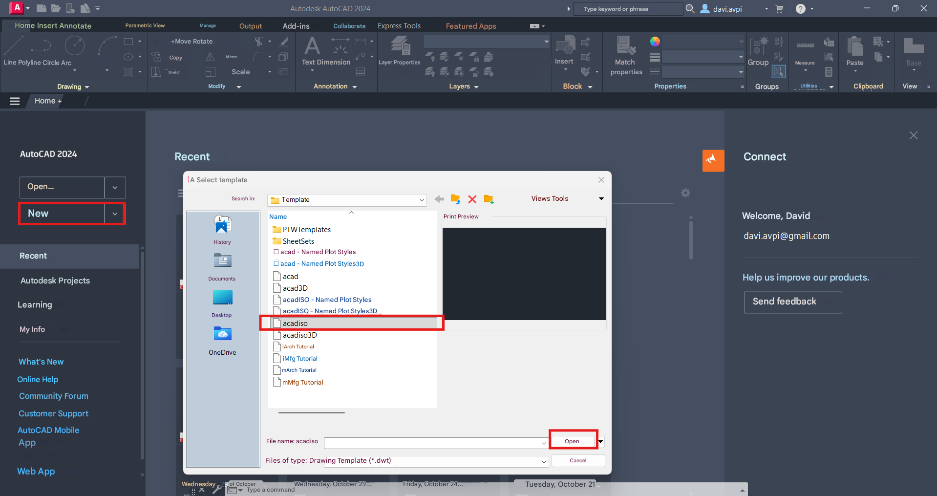 An important initial configuration is being able to know in metric units the drawing will be done, in this case I chose millimeters.
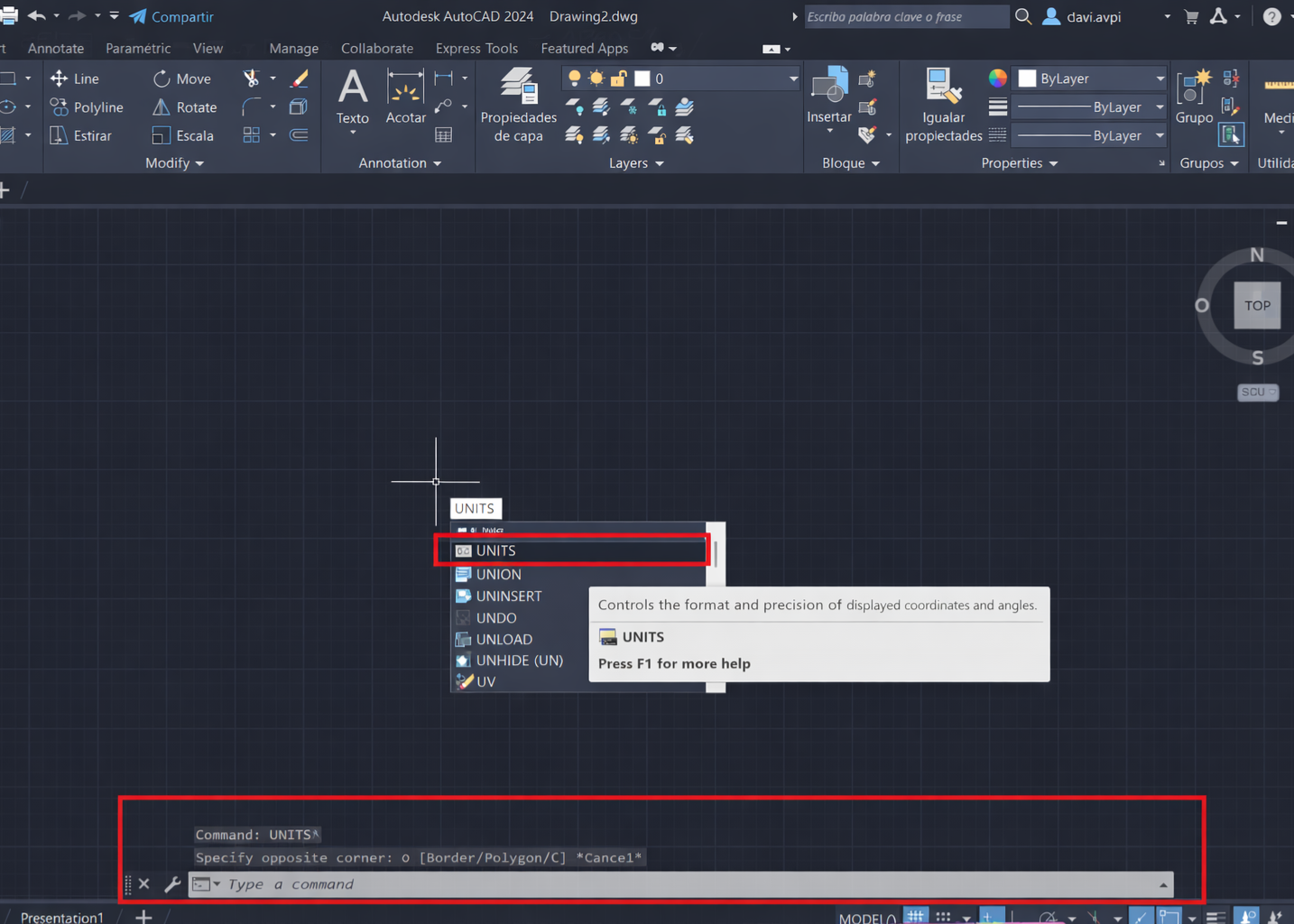
Drawing Units
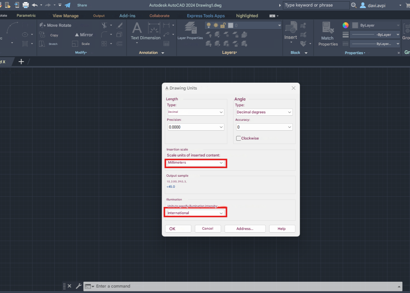
Drawing Units
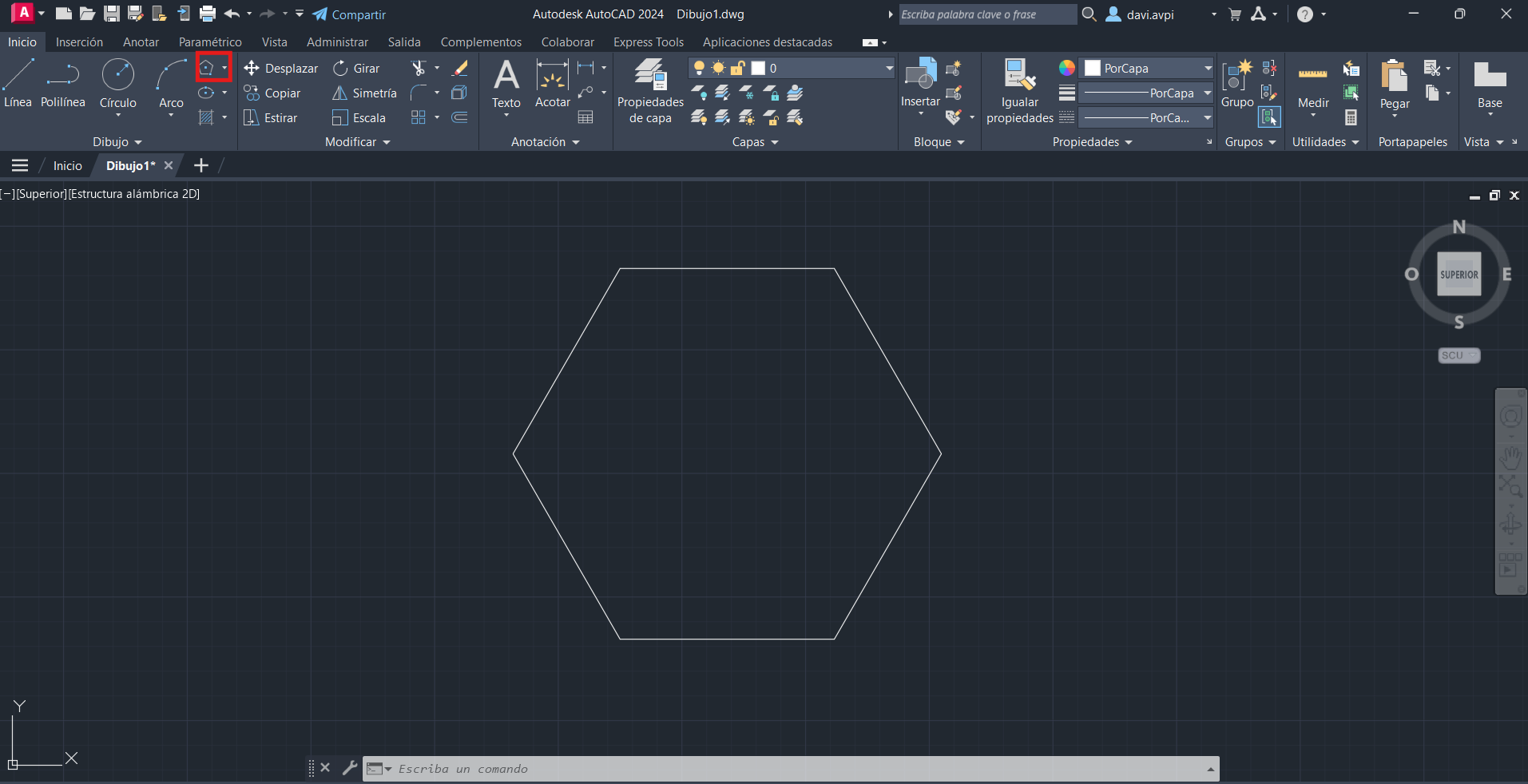
AUTOCAD Commands
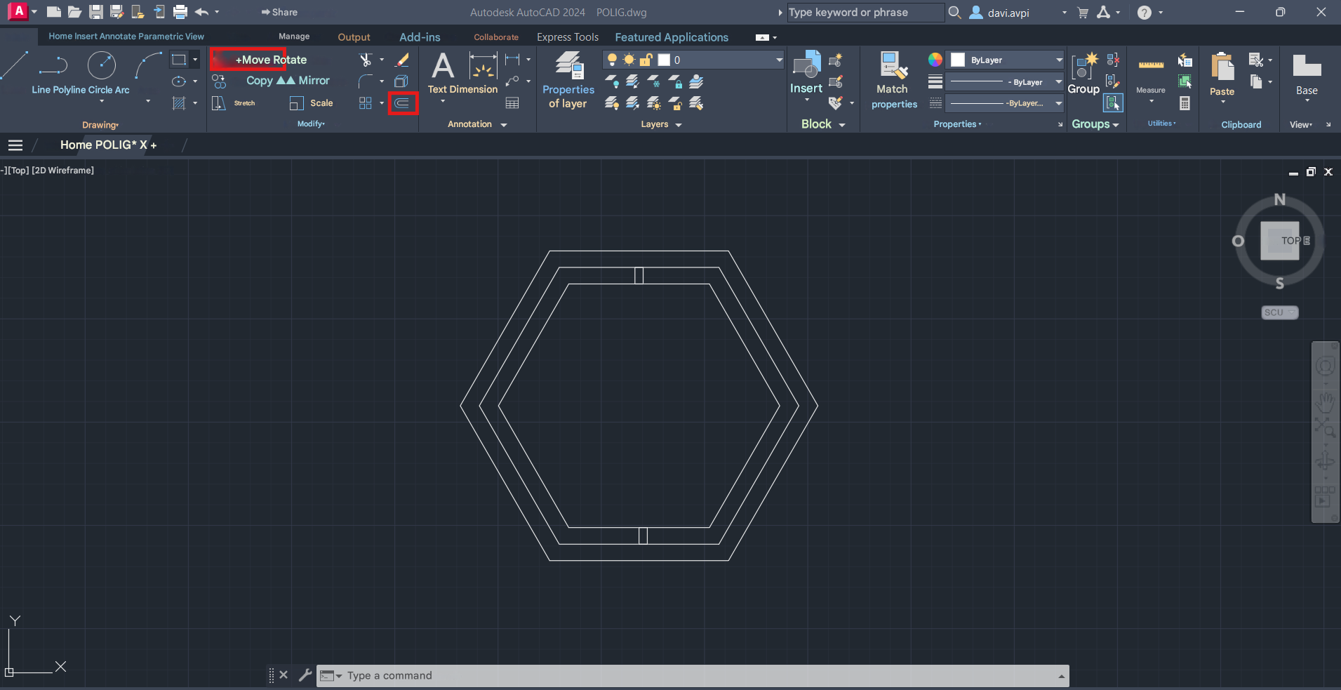
AUTOCAD Commands
AUTOCAD Commands
Export Drawing
Second Step / Result

COREL DRAW
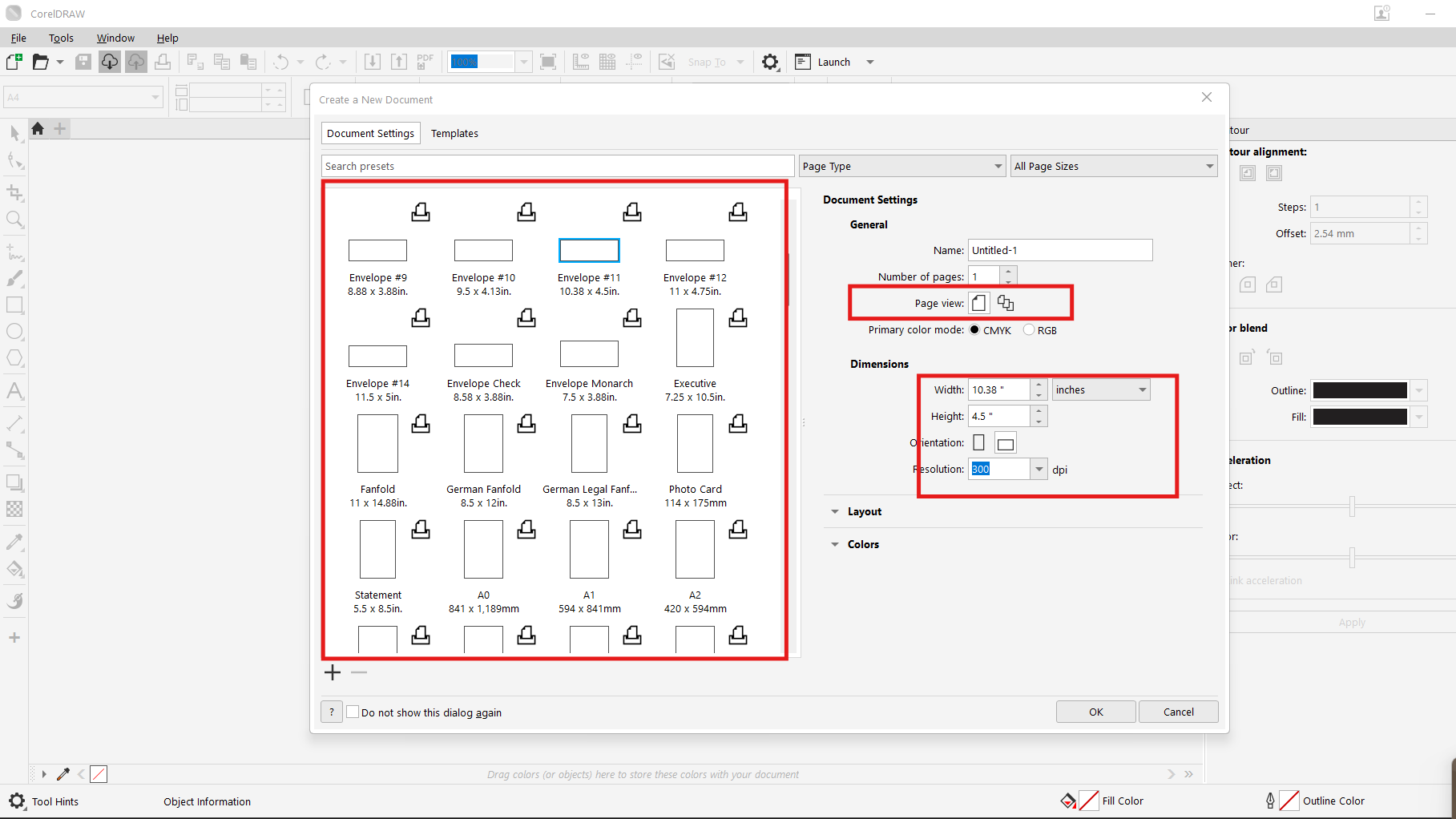
A worksheet is created to begin working, either configured to exact measurements and with the required units, such as the actual material we have if we are going to use it for cutting or if a print design or website is being made.
Step 1
Step 2
Setup 3
3D Design - Model

SOLIDWORKS
Tinkercad
Step 1
Step 2
AI RENDER

GROK
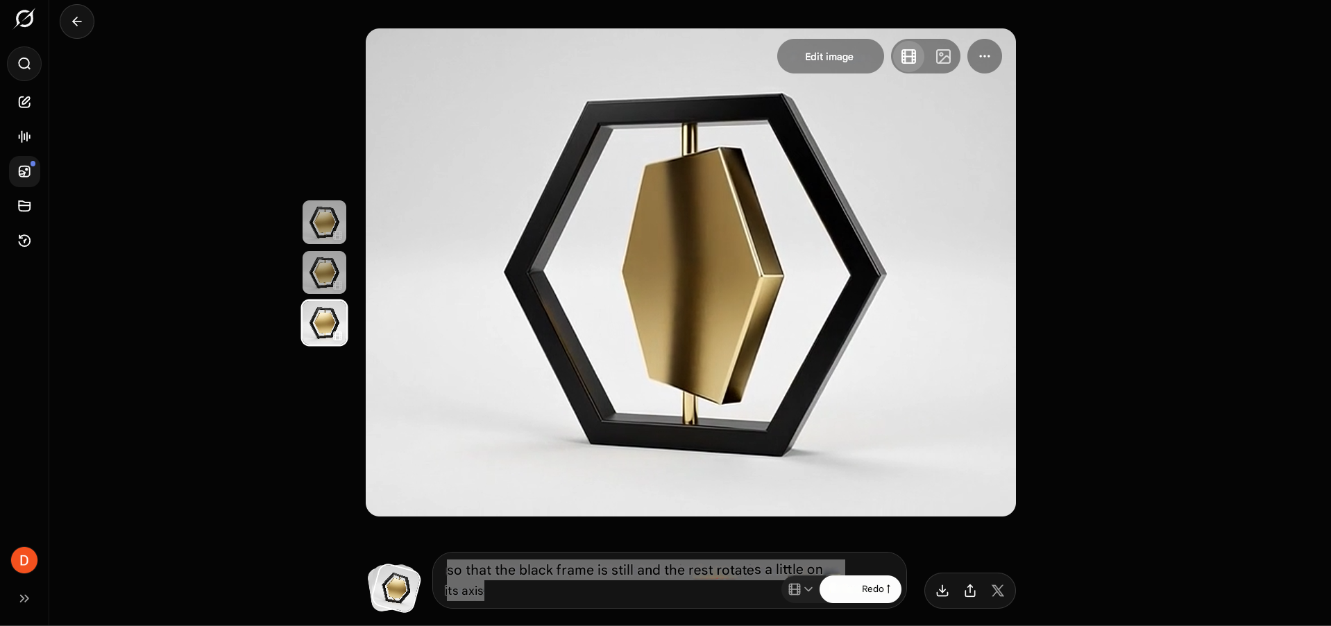


IMAGE COMPRESSOR
ILOVEIMG
First, we open the website: ILOVEIMG Compressor
VIDEO COMPRESSOR
FREECONVERT
First, we open the website: FREECONVERT Video Compressor
Step 1
Step 2
FILES